Photoshop CS4 Studio Techniques- P9 pdf
Bạn đang xem bản rút gọn của tài liệu. Xem và tải ngay bản đầy đủ của tài liệu tại đây (1.63 MB, 30 trang )
226
Chapter 6 Sharpening
The procedure we’ve just discussed is the usual approach
to sharpening most images, but sometimes you’ll need to
go a different route. The Radius setting can have a radi-
cal effect on sharpening. You’ll need to achieve a bal-
ance between Amount and Radius. High Amount settings
(about 90–250) will require low Radius settings (.5–1.5),
and low Amount settings (10–30) will require higher
Radius settings (5–20). High Amount settings work for
most images, and that’s why we took the initial approach
just mentioned.
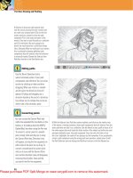
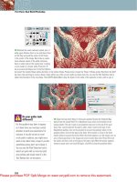
If you have a grainy image and you want to maintain but
not exaggerate the grain (Figure 6.38), you’ll need to take
a slightly different approach. A grainy image will start to
look unusual when you get an Amount setting anywhere
near 100–150 (Figure 6.39); you might even need to bring
the Amount setting down to near 20 before the grain stops
being exaggerated too much. At that point, you’ll barely
be able to tell that the image has been sharpened (Figure
6.40); to compensate, you’ll need to get the Radius setting
up until the image starts to look sharp (Figure 6.41). On
most images, you’ll be able to use much higher Amount
settings without causing grain problems. In that case, you
might end up with an Amount setting around 120, and
then you’ll need to experiment with the Radius setting to
see what looks best (probably between .5 and 1.5).
Figure 6.37 Adjust the Amount set-
ting until the image looks realistically
sharp.
227
II: Production Essentials
Figure 6.40 With the Amount setting at 20,
the grain is less, but the image doesn’t look
sharp.
Figure 6.39 With the Amount setting at 150,
the grain is becoming too obvious. (Look
very closely to see the difference between
this figure and Figure 6.38.)
Figure 6.41 With the Amount setting at 20
or so and the Radius up to 1.5, the image
becomes sharp.
Figure 6.38 An old grainy image. (©2008
Dan Ablan.)
228
Chapter 6 Sharpening
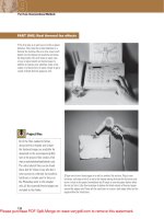
Using Smart Sharpen
The Smart Sharpen fi lter (Figure 6.42) expands on the
concepts of the Unsharp Mask fi lter to deliver a more
sophisticated method for sharpening images. However,
there are many instances where you might prefer the
Unsharp Mask fi lter, for reasons explained in a moment.
The Amount and Radius settings in the Smart Sharpen
fi lter work just like the ones in the Unsharp Mask fi lter.
In fact, the results are identical when the Remove pop-up
menu is set to Gaussian Blur (Figure 6.43). Setting the
Remove menu to Lens Blur causes the halos that come
along with sharpening to be less pronounced, which allows
you to get away with higher Amount and Radius settings
before the sharpening halos become overly obvious
(Figure 6.44). You can use this setting whenever quality
is more important than speed (which is often the case in
normal workfl ow). You can also set the Remove pop-up
menu to Motion Blur and then experiment with the Angle
setting to reduce the blurring effect of lens shake. It’s not
a miracle worker, though, so it will only be effective when
the camera shake was almost unnoticeable.
Turning on the More Accurate check box causes the
image to be sharpened in two passes (just like applying the
Unsharp Mask fi lter twice). This can make edges much
more prominent (Figure 6.45), but you have to be very
Figure 6.42 The Smart Sharpen
dialog, with the Remove option set to
Gaussian Blur. (©2008 Dan Ablan.)
Figure 6.43 Gaussian Blur setting.
Figure 6.44 Lens Blur setting.
Figure 6.45 Lens Blur setting with
More Accurate check box turned on.
229
II: Production Essentials
careful because it also has a tendency to over-exaggerate
grain and noise in images.
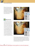
You might fi nd that you’ll use the Unsharp Mask fi lter for
images that contain fi ne texture, such as skin or brick,
because the Smart Sharpen fi lter does not offer the
Threshold setting that allows you to limit the sharpening
effect to areas of more pronounced detail.
Advanced Mode
The Smart Sharpen fi lter also offers an Advanced mode,
which allows you to control the strength of the sharpening
that will be applied to the shadows and highlights of the
image (Figure 6.46). This feature can be useful in instances
when a considerable amount of noise is present in the dark
portion of an image. The Fade Amount setting determines
the strength of the sharpening effect; the Tonal Width set-
ting determines the brightness range that will be affected
by the sharpening, and the Radius setting determines how
the sharpening effect will blend into the surrounding
image. A good way to work is to start with Fade Amount
at 100% and Radius at 3 so that you can see the full
effect of the sharpening. Then adjust Tonal Width until
the sharpening no longer affects any overly noisy areas.
Finally, adjust the Fade Amount slider to see just how much
sharpening you can use without exaggerating the noise in
the image.
Figure 6.46 Advanced options.
230
Chapter 6 Sharpening
More Art Than Science
The process of sharpening takes a good bit of practice
before you start feeling confi dent. Everyone has a different
idea of how sharp an image should look, and most output
devices aren’t capable of reproducing the amount of detail
you see onscreen. Even if you sharpen the image so that it
looks great onscreen, when you print the image it might
still look rather soft. Following are some general thoughts
on how to approach sharpening for different types of
output:
. Web/multimedia: When the fi nal image will be
displayed onscreen, you can completely trust your
screen when sharpening the image. Most of the time
you’ll end up with Radius settings between .5 and 1
and Amount settings below 100%. Just be aware that
sharpening increases the fi le size of JPEG fi le format
images (Figures 6.47 to 6.49). If you’re planning to save
the image as a JPEG fi le, use the absolute minimum
amount of sharpening that makes the image look crisp.
Figure 6.47 The original unsharpened
image. (©2008 Dan Ablan.)
Figure 6.48 The image from Figure
6.47, sharpened with settings of
Amount 70, Tonal Width 5, and
Radius 4.
Figure 6.49 The image from Figure
6.47, sharpened with settings of
Amount 175, Tonal Width 7, and
Radius 4.
. Photographic output devices: These devices include
fi lm recorders, LightJets, and other gadgets that use
231
II: Production Essentials
photographic fi lm or paper to reproduce an image.
They can reproduce the majority of the detail you see
onscreen. With these devices you have to be very care-
ful to make sure that the Radius setting is quite low (.25
to .7 for most images), so that the halos that come from
sharpening aren’t obvious on the end result.
. Desktop printer: This includes inkjet and laser printers.
Experiment with an image that’s representative of the
type of image you use the most.
. Commercial printing press: Start by sharpening images
until they look very sharp onscreen, and then analyze
the printed result when you get a job back from the
printing company. If the printed result doesn’t look
too sharp, slowly ratchet up the Amount and Radius
settings on subsequent images until the printed images
look very sharp, but still natural. Compare the printed
result to the original digital fi le each time, viewing the
image at 100% magnifi cation. As you work on more
and more jobs, you’ll start to get a feeling for how
much you need to overdo the sharpening onscreen to
get a nice sharp end result. Different types of print-
ing produce differing amounts of detail. (Newspaper
images need to be sharpened much more than images
that will be printed in a glossy brochure.)
If thinking about all the different settings needed for
different output devices drives you crazy, consider adding
a commercial plug-in fi lter to Photoshop. Nik Software
(www.niksoftware.com) makes a set of plug-in fi lters known
as Sharpener Pro (Figure 6.50), which takes a lot of the
guesswork out of sharpening images. The package comes
with separate fi lters for different types of output (includ-
ing inkjet, color laser, offset printing, and Internet) and
compensates for different viewing distances and image
sizes, all without having to think about Amount, Radius,
and Threshold settings. The results might just be a little bit
too aggressive; if so, choose Edit > Fade immediately after
applying the fi lter, and lower the Opacity setting a bit. It
might be a personal preference as to what you consider to
be a naturally sharp result, so the fi nal Opacity setting will
be unique to you.
Figure 6.50 Nik Sharpener Pro takes a lot of the
guesswork out of sharpening.
232
Chapter 6 Sharpening
Do you plan to use an image for more than one purpose?
Ideally, you should create a unique version of the image
for each use. Choose Image > Duplicate to create an
exact copy of an image. Then choose Image > Image Size
(Figure 6.51) to set the proper size and resolution for the
output device for which this particular image is destined.
Finally, sharpen the image based on your experience with
that particular device. As you repeat the process for other
devices, always go back to the full-sized master image
before repeating the steps.
If you simply can’t deal with one image for each device,
work with a single image and do the following: Set the
resolution to what’s needed for your most demanding
output device (the one that needs the highest-resolution
image), and sharpen for the device that looks closest to your
screen (the one that needs the least radical sharpening).
Then use that one image for all output devices. That’s
kind of like buying one shoe size for an entire basketball
team. As long as it’s large enough for the biggest person,
everyone should be able to fi t in it, but it won’t be ideal
for everyone.
Tricks of the Trade
Now that we’ve talked about the general process of sharp-
ening an image, let’s start to explore some more advanced
ideas that will allow you to get more control over your
sharpening.
Sharpen Luminosity
If you look closely at a color image after it’s sharpened,
you might notice bright-colored halos around objects
that were not all that colorful in the original photo. (In
Figure 6.52, notice the green fringe around the blue
shirt.) To prevent that type of unwanted sharpening
artifact, choose Edit > Fade Unsharp Mask immediately
after sharpening an image. When the Fade dialog appears,
set the Mode pop-up menu to Luminosity and then click
OK (Figure 6.53). That will force the sharpening you just
applied to affect only the brightness of the image and will
prevent it from shifting or intensifying the colors in the
Figure 6.51 Use the Image Size dialog
to specify the size and resolution of
the image.
233
II: Production Essentials
image (Figure 6.54). If you read a lot of books and maga-
zine articles about Photoshop, you might discover that
many people attempt to get the same result by converting
their image to LAB mode and then sharpening the image.
The only problem with that approach is that any time you
change the mode of an image, you lose a little quality. So
try to switch modes only when you have a good reason to
do so. Fading after applying the Unsharp Mask fi lter gives
you the same benefi ts as converting to LAB mode, so try to
leave the image in its original mode when sharpening.
Figure 6.52 You can get colored halos around objects in an image when
sharpening.
Figure 6.53 Use Fade directly after
using the Unsharp Mask filter to
have the sharpening affect only the
brightness in the image.
Figure 6.54 A closeup view of the
sharpened image, now without
fringing.
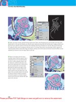
Sharpen the Black Channel
If an image is destined for CMYK mode, be sure to make
an extra sharpening pass on the black channel. Just open
the Channels panel (Window > Channels), click the Black
channel, and sharpen away. Because black ink is mainly
used in the darker areas of the image, you can get away
with some rather aggressive settings. (Try these: Amount =
350, Radius = 1, Threshold = 2.) Perform this sharpening
pass after you’ve already sharpened the full-color image
(Figures 6.55 to 6.57).
Remember, in order to sharpen the
black channel, the image needs to
be in CMYK mode. Choose Image >
Mode > CMYK Color.
234
Chapter 6 Sharpening
Figure 6.55 The original image,
unsharpened. (©2008 Dan Ablan.)
Figure 6.56 Unsharp Mask filter
applied to the RGB channels.
Figure 6.57 Sharpening added to just
the black channel.
235
II: Production Essentials
Sharpen Channels Separately
Certain images don’t look good after being sharpened. For
instance, when you sharpen a face, it sometimes seems to
just fall apart, making the person look years older. Another
example would be scanned images in which color noise is
exaggerated. In those cases, consider clicking through the
channels that appear in the Channels panel and sharpen-
ing only the channels that would help the image. For light
skin, that would be the channel that’s the lightest—red
in RGB mode or cyan in CMYK mode (Figures 6.58 to
6.60). For noisy images, avoid sharpening the channel that
contains the most noise—usually blue in RGB mode or
yellow in CMYK mode. You shouldn’t use this technique
every time you want to sharpen images, but it’s something
to think about when sharpening a full-color image is doing
more harm than good.
Figure 6.58 Red channel. (©2008
Dan Ablan.)
Figure 6.59 Green channel. Figure 6.60 Blue channel.
Control Highlights and Shadows Separately
When you sharpen an image, Photoshop adds a dark halo
on one side of an edge and a bright halo on the opposite
side of the edge. When you’re working with dark back-
grounds, such as a deep blue sky, the bright halos can
be rather easy to see (Figure 6.61). Try controlling the
bright and dark halos separately so that you can minimize
the bright halo while maintaining the dark one. You can
236
Chapter 6 Sharpening
accomplish that goal by making two duplicates of the layer
you want to sharpen. Click each of the duplicate layers
and set the Blending Mode pop-up menu at the top of
the Layers panel to Lighten for one and Darken for the
other (Figure 6.62). Now you can sharpen the two layers
separately. The setting you apply to the layer that is set to
Lighten will control the bright halos; the setting on the
layer set to Darken will control the dark halo (Figure 6.63).
Figure 6.61 The bright halos in this
image are getting obvious.
Figure 6.62 Duplicate the layer twice;
set one layer to Lighten mode and the
other to Darken mode.
Figure 6.63 When you separate the
dark and bright halos, you have more
control over them.
The Next Step
If you felt like you were drowning in details in this chapter,
try a few of the techniques; then come back and read it
again, and things will start to gel. It may take you a while
to become truly comfortable with sharpening images, but
it’s well worth the time because you can transform fl at and
lifeless images into ones that are lively and ready to pop
off the page. Now, here’s one more very important piece
of sharpening advice before we head to the next chapter:
Oversharpened images never look good, so if you’re ever
unsure of how much sharpening to apply, err on the side
of conservatism.
Chapter 7: Setting Up Images for Final Output 237
Chapter 8: Color Manipulation 271
Grayscale, Color, and Print
III
This page intentionally left blank
CHAPTER
7
Setting Up Images for
Final Output
240
Artists can color the sky red because they know
it’s blue. Those of us who aren’t artists must color
things the way they really are or people might
think we’re stupid.
—Jules Feiffer
Setting Up Images for
Final Output
N
o question—your job as a photographer is to capture
the image. But in today’s ever-changing digital landscape,
it’s also your job to make sure that the image is the best it
can be. And in order to do that, you need to master the
color and contrast of the image.
This chapter will guide you through understanding the
color and grayscale values within your imagery. You’ll
see the difference between Levels and Curves, while also
learning that grayscale is more than just a desaturation. To
begin, we’ll discuss some of the more obvious variables in
the image-editing process: brightness and contrast.
Brightness and Contrast
Years ago, Photoshop’s Brightness/Contrast dialog used
to adjust the entire tonal range of an image by equal
amounts, which made it diffi cult to adjust one part of the
image—say, the shadows—without destroying another part
of the image, such as the highlights. However, Adobe has
reengineered the Brightness/Contrast dialog with recent
updates, and turned it into a very useful, very powerful
tonal adjustment tool.
To fi nd the Brightness/Contrast adjustment, choose
Image > Adjustments > Brightness/Contrast. The dialog
is very straightforward (Figure 7.1). By sliding the Bright-
ness slider back and forth, you can make the overall image
brighter or darker. In general, the Brightness slider protects
The techniques described in this
chapter are used by the high-paid
color maestros who are responsible
for all of those ever-so-perfect
glossy magazine ads. It will take
you a while to really get the hang
of these techniques, but once you
do, it should take you just minutes
to correct most images.
Figure 7.1 The Brightness/Contrast
dialog.
241
III: Grayscale, Color, and Print
shadow areas—it won’t usually let you underexpose them
too far. Therefore, you need to keep a very close eye on the
highlights in the image. As you adjust the slider, be careful
that you don’t let the highlights overexpose and blow out to
complete white, losing detail (Figure 7.2).
The Contrast slider increases contrast in an image by
brightening the light parts and darkening the darker areas
(Figure 7.3). The overall effect is an image with more
“pop” and better detail. Too much contrast, however, and
the image can appear muddy. Moving the slider to the left
lowers the contrast, resulting in a fl atter image (Figure 7.4).
Brightness/Contrast is not the most refi ned tool, but it
can be a great place to start if you’re relatively new to
Photoshop.
Figure 7.3 Use the Contrast slider to add “punch” to images. Figure 7.4 Slide the Contrast slider left to pull contrast out
of an image.
Figure 7.2 As you slide the Brightness
slider left or right, the image becomes
darker or lighter, respectively. (©2008
Dan Ablan.)
242
Chapter 7 Setting Up Images for Final Output
Adjusting Levels
Brightness/Contrast is especially useful if you’re new to
performing tonal corrections; for many images, it’s all
the control you’ll ever need. However, Photoshop’s Levels
adjustment (Image > Adjustments > Levels) provides a
more sophisticated tool that offers a much fi ner degree of
control (Figure 7.5). Levels provides fi ve different slid-
ers that you can adjust, as well as a histogram (sort of like
a bar graph) that indicates exactly what’s happening to
the image.
Forces shades
to black
Brightens or darkens shades
between white and black
Changes black to
a shade of gray
Forces shades
to white
Changes white to
a shade of gray
The Histogram Is Your Guide
You can use the histogram at the top of the Levels dialog
to determine whether the adjustments you’re making are
going to harm the image or improve it. The histogram
indicates which shades of gray the image uses and how
prevalent those shades are within the image (Figure 7.6).
The peaks indicate a shade of gray that takes up a lot of
space in the image, and the valleys indicate a shade that
isn’t very prevalent in the image. A histogram that extends
all the way across the space available and doesn’t have tall
Figure 7.5 The Levels sliders.
To reset sliders to their default
positions, hold down Option/Alt
to change the Cancel button to a
Reset button temporarily.
243
III: Grayscale, Color, and Print
spikes on either end indicates an image that has the full
range of shades available, and is usually a sign of a good
scan or a well-adjusted image. If you fi nd a gap in the histo-
gram, you can look at the gradient directly below it to see
which shade of gray is missing from the image.
Figure 7.6 This histogram indicates that the shades between around 90% and
75% gray take up a lot of space (tall bars), and the shades between around 5%
and 15% take up little space (short bars).
By looking below the left side of the histogram, you can
determine the darkest shade of gray in the image. By look-
ing below the right end of the histogram, you can deter-
mine the brightest shade of gray in the image. In Figure
7.7, you might notice that the image contains no pure
blacks or pure whites. The darkest shade of gray is about
95%, and the brightest shade is about 6%.
Figure 7.7 Look at the gradient bar
directly below the ends of the histo-
gram to determine the brightest and
darkest shades present in the image.
There is no ideal setting for a histogram; it’s simply a rep-
resentation of which shades of gray are most prevalent in
the image (Figure 7.8).
The height of the bars in a
histogram suggest how much space
the shades take up in an image.
The height doesn’t indicate an
exact number of pixels; instead, it
measures how much that shade is
used as compared with the other
shades in the image. It’s as if every-
one in a room stood up and you
visually compared how tall each
person was (without using a ruler).
You wouldn’t know exactly how
tall anyone was, but you’d have an
idea of how tall each person was as
compared with the others.
244
Chapter 7 Setting Up Images for Final Output
Figure 7.8 Each image has its own unique histogram. (©2008 Dan Ablan.)
Evaluating and Adjusting Contrast
The brightest and darkest areas of your computer moni-
tor are nowhere near as bright or dark as the objects in
the real world. The difference is even more extreme when
you look at the brightest and darkest areas of a printed
brochure—the paper is actually pretty dull, and the ink
isn’t all that dark. You’ll need to use the full range of
shades from black to white in order to make your photos
look as close to reality as possible.
By adjusting the upper-right and upper-left sliders in the
Levels dialog, you can dramatically improve the contrast
of an image and make it appear more lifelike. When you
move the upper-left slider in the Levels dialog, you force
the shade of gray directly below it and any shade darker
than it (see the gradient) to black. So moving that slider
until it touches the fi rst bar on the histogram forces the
darkest shade of gray in the image to black, which should
give you nice dark shadows.
The middle slider moves when you
adjust the upper-right or upper-left
slider. This happens because Pho-
toshop is attempting to keep the
middle slider in the same position
relative to the other two sliders.
So if the middle slider is centered
between the other two sliders, it
will remain centered when you
move one of the outer sliders.
245
III: Grayscale, Color, and Print
When you move the upper-right slider, you force the
shade that appears directly below the slider and any shade
brighter than it to white. Moving the right slider until it
touches the last bar on the histogram forces the brightest
shade of gray to white, which should give you nice white
highlights.
By adjusting both sliders, you make the image use the full
range of shades available to a grayscale image (Figure 7.9).
If you move the sliders past the beginning and end of the
histogram, you’ll get even more contrast, but you risk los-
ing important detail in the process.
Figure 7.9 The shades that are
beyond the upper-right and upper-
left triangles on the Input Levels
histogram become pure black and
pure white, as shown on the Output
Levels gradient.
Threshold Mode to the Rescue
To achieve maximum contrast without sacrifi cing detail,
Adobe created a hidden feature in the Levels dialog. It’s
known as Threshold mode. This feature allows you to see
exactly which areas are becoming black or white, and it’s
the key to ensuring that you don’t sacrifi ce detail. To get
to the hidden feature, hold down the Option/Alt key
when you move the upper-right or upper-left slider in the
Levels dialog.
When you move the upper-left slider with Threshold mode
turned on, the image should turn white until the slider
touches the fi rst bar on the histogram; then small black
areas should start to appear. These are the areas that will
become pure black. With most images, you shouldn’t force
a large concentrated area to black, so move the slider only
until small areas of black appear. You also want to make
sure that the areas that are becoming black still contain
If you’re in the market for a new
scanner, be sure to compare the
Dmax specifications for each
scanner you’re considering. Higher
Dmax specs indicate a scanner
that’s capable of capturing more
shadow detail than you’ll get
from a scanner with a lower Dmax
spec. If you can’t find the Dmax
specification on the manufacturer’s
Web site, there’s a good chance
that it’s too low to mention. It’s
often worth the extra money to
get a scanner that can deliver good
shadow detail.
246
Chapter 7 Setting Up Images for Final Output
detail. Detail will show up looking like visual “noise,” so
make sure that those small areas also look noisy. Repeat
this process with the upper-right slider to get optimal
contrast (Figures 7.10 to 7.14).
Figure 7.10 The original image.
(©2008 Dan Ablan.)
Figure 7.11 Here, the upper-left slider
is adjusted much too far.
Figure 7.12 With the upper-left slider
adjusted as shown in Figure 7.11, large
areas of the image are losing detail
and becoming pure black.
Figure 7.13 Now the upper-left slider
is adjusted correctly.
Figure 7.14 Small areas become black
but still contain detail (noise).
Three things might cause an image to have large areas of
black or white from the start:
. The image was scanned in, and the scanner wasn’t
capable of capturing good shadow detail.
. The image simply didn’t have any detail in the shadows.
. The image has been adjusted without using Photo-
shop’s Threshold mode.
247
III: Grayscale, Color, and Print
The Histogram Gives You Feedback
After applying an adjustment to an image, you can see an
updated histogram by choosing Image > Adjustments >
Levels again. Notice that after you’ve adjusted the upper-
right and upper-left sliders, the histogram stretches all the
way across the area available. It’s just like stretching out a
Slinky—you remember, “It walks down stairs, alone or in
pairs” (Figure 7.15). As you pull on the ends of a Slinky,
the loops stretch out and start to create gaps. The same
thing happens to a histogram—because Photoshop can’t
add more bars to the histogram, it can only spread out the
ones that were already there. And remember, gaps in the
histogram mean that certain shades of gray are missing
from the image. So the more you adjust an image using
Levels, the more you increase the possibility that you’ll lose
some of the smooth transitions between bright and dark
areas (Figure 7.16).
If you see large spikes on either end of the histogram (Fig-
ure 7.17), it’s an indication that you’ve lost detail. That’s
because you forced quite a bit of space to white or black
by using Levels. But you’d know you did that, because you
used the hidden feature, right? Or maybe you couldn’t
control yourself and used that Brightness/Contrast dialog,
where you can’t tell if you damaged the image! You might
also get spikes on the ends of the histogram (Figure 7.18)
if you scan an image with too high of a contrast setting, or
a brightness setting that’s too high or low, or if the image
was scanned in and your scanner isn’t capable of capturing
enough shadow detail.
Figure 7.17 Spikes on the end of a
histogram usually indicate lost detail.
Figure 7.18 Noise.
Figure 7.15 A Slinky®.
Figure 7.16 After you adjust the top
two sliders, the image should use the
full range of shades available.
248
Chapter 7 Setting Up Images for Final Output
Adjusting Brightness After Contrast
After you have achieved good contrast, the image might
look too bright or dark. The middle slider in the Levels
dialog can fi x that. (Techies call this slider the gamma set-
ting, but we plain folks call it the midpoint.) If you move the
middle slider to the left, the image becomes brighter with-
out messing up the dark areas of the image. Black areas stay
nice and black. Or you can move the middle slider to the
right to darken the image without messing up the bright
areas. White areas stay bright white (Figure 7.19). This is
the one setting in which you must use your own judgment,
based on how bright or dark you want the image to be.
If you want to know what this adjustment is doing, just look
directly below the middle slider; the shade of gray there
will become 50% gray. Moving it to the left brightens the
image because you’re shifting what used to be a dark shade
of gray to 50% gray. Moving the middle slider to the right
darkens the image as you shift a bright shade to 50% gray.
If you look at an updated histogram of the image, it will
look like you stretched out a Slinky, and then grabbed one
side and pulled it to the middle (Figure 7.20). Some bars
get scrunched together, others spread apart.
Figure 7.20 The adjustment shown on the left results in the histogram shown
on the right.
Figure 7.19 Effects of the middle
slider.
To see a histogram that changes
continuously to reflect any modi-
fications you make to the image,
choose Window > Histogram.
Spikes that show up after an image
has been adjusted with Levels don’t
indicate noise. Let’s say you try to
squish 20 bars on the histogram
into a space that’s only 15 pixels
wide. Five of the bars have to disap-
pear. They’re just going to pile on
top of the bars next to them and
make those bars about twice as tall.
When this happens, you get evenly
spaced spikes across part of the
histogram.
249
III: Grayscale, Color, and Print
Prepping for Print
If images are going to be printed on a commercial print-
ing press, chances are that they’ll end up looking a lot
darker than they did when you viewed them onscreen. This
is known as dot gain. Fortunately, Photoshop allows you to
compensate for dot gain. You can tell Photoshop ahead of
time how you intend to output the images, and the soft-
ware will adjust the onscreen appearance of the image to
look as dark as it should be when printed.
To select or enter dot gain settings, choose Edit > Color
Settings. In the Working Spaces area of the Color Settings
dialog, use the Gray pop-up menu (Figure 7.21). Ask your
printing company what settings to use; otherwise, you’ll
just be guessing and you might not like the end result. If
you don’t have time to ask your printing company, you can
use the settings in Table 7.1. After you’ve specifi ed the Dot
Gain setting that’s appropriate for your printing condi-
tions, choose Image > Mode > Assign Profi le, and select
the Working Gray setting. That will set up Photoshop to
preview the image properly for the specifi ed conditions.
If the dot gain setting you need isn’t
listed in the Working Spaces area,
you’ll need a custom setting. Select
Custom from the settings at the
top of the dialog, and then choose
Custom Dot Gain from the Gray
pop-up menu.
TABLE 7.1 Dot Gain Settings
FORMAT SETTING
Newspapers 34%
Magazines and brochures 24%
High-end brochures 22%
Figure 7.21 The Color Settings dialog.
250
Chapter 7 Setting Up Images for Final Output
Preparing for a Printing Press
Take a close look at the black-and-white image in Figure
7.22, and imagine that you took that image to your local
copy shop and made a copy of it (copy #1). Then you
copied copy #1 to make copy #2. Then you took copy #2
and ran it through the copy machine in your offi ce, making
copy #3. At this point, you held copy #3 next to the original.
Would you expect them to look the same? Of course not. In
fact, the tiny dots that are in the brightest part of the image
would have begun to disappear and become pure white—
because every time you make a copy, you lose some quality.
The same thing happens when you hand over an image to
a printing company; the fi nal printed version is three levels
of copying away from the original. The original is used to
create a piece of metal called a printing plate (copy #1).
The plate is put on a big roller on the printing press and
fl ooded with water and ink. The oily ink sticks to the plate
only where the images and text should be; the water makes
sure that it doesn’t stick to the other areas (following the
principle that oil and water don’t mix). Next to that roller
is another one known as a blanket; it’s just covered with
rubber. The plate comes into contact with the blanket so
that the ink on the plate will transfer over to the blanket—
that’s copy #2. Finally, the blanket transfers the ink onto a
sheet of paper to create copy #3 (Figure 7.23).
Figure 7.22 The farther the copy from
the original image, the more detail
lost in the brightest part of the image.
(©2008 Dan Ablan.)