Mechanism Design - Enumeration of Kinematic Structures According to Function P1 pptx
Bạn đang xem bản rút gọn của tài liệu. Xem và tải ngay bản đầy đủ của tài liệu tại đây (1.05 MB, 19 trang )
Chapter 1
Introduction
1.1 Introduction
Design is the creation of synthesized solutions in the form of products or systems
that satisfy customer’s requirements [9, 25, 30, 34]. When we are given a design
problem, we try to make the best use of our knowledge and the available information
to understand the problem and generate as many feasible solutions as possible. Then,
we evaluate these concepts against the customer’s requirements and select a most
promising concept for design analysis and design optimization. We may think of the
design as a mapping of the customer’s requirements into a physical embodiment. The
better we understand the problem associated with the customer’s requirements, the
better design we can achieve.
The design process can be logically divided into three interrelated phases: (1) prod-
uct specification and planning phase, (2) conceptual design phase, and (3) product
design phase. During the product specification and planning phase, we identify the
customer’s requirements and translate them into engineering specifications in terms
of the functional requirements and the time and money available for the development,
and plan the project accordingly. In the conceptual design phase, we generate as
many design alternatives as possible, evaluate them against the functional require-
ments, and select the most promising concept for design detailing. A rough idea of
how the product will function and what it will look like is developed. In the product
design phase, we perform a thorough design analysis, design optimization, and simu-
lation of the selected concept. Function, shape, material, and production methods are
considered. Several prototype machines are constructed and tested to demonstrate
the concept. Finally, an engineering documentation is produced and the design goes
into the production phase. However, if the concept selected for the product design
is shown to be impractical, it may be necessary to go back to the conceptual design
phase to select an alternate concept or to generate additional concepts. In this re-
gard, it may be necessary to reevaluate the engineering specifications developed in
the product specification and planning phase.
Design is a continuous process of refining customer requirements into a final prod-
uct. The process is iterative in nature and the solutions are usually not unique. It
© 2001 by CRC Press LLC
involves a process of decision making. A talented and experienced engineer can
often make sound engineering decisions to arrive at a fine product. Although the
third phase is usually the most time consuming phase, most of the manufacturing cost
of a product is committed by the end of conceptual design phase. According to a
survey, 75% of the manufacturing cost of a typical product is committed during the
first two phases. Decisions made after the conceptual design phase only have 25%
influence on the manufacturing cost. Therefore, it is critical that we pay sufficient
attention to the product specification and conceptual design phases. One approach
for the generation of concepts is to identify the overall function of a device based
on the customer’s requirements, and decompose it into subfunctions. Then, various
concepts that satisfy each of the functions are generated and combined into a complete
design. Techniques for generation of concepts include literature and patent search,
imitation of natural systems, analysis of competitor products, brainstorming, etc.
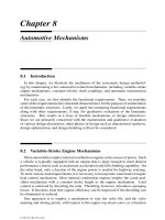
In this text, we concentrate on the conceptual design phase of mechanisms. The
conceptual design is traditionally accomplished by the designer’s intuition, ingenu-
ity, and experience. An alternate approach is to generate an atlas of mechanisms
classified according to functional characteristics for use as the sources of ideas for
mechanism designers [1, 17, 19, 20, 21, 24]. This approach, however, cannot en-
sure the identification of all feasible mechanisms, nor does it necessarily lead to an
optimum design.
Recently, a new approach based on an abstract representation of the kinematic
structure, which is somewhat similar to the symbolic representation of chemical
compounds, has evolved. The kinematic structure contains the essential information
about which link is connected to which other links by what types of joint. It can be
conveniently represented by a graph and the graph can be enumerated systematically
using combinatorial analysis and computer algorithms [6, 7, 8, 10, 13, 15, 35]. This
approach, which appears to be promising, is the basis of this text.
In the following, we briefly introduce the methodology and review some of the
fundamentals of the kinematics of mechanisms to facilitate the development of the
methodology.
1.2 A Systematic Design Methodology
The methodology is based on the application of graph theory and combinatorial
analysis. First, the functional requirements of a class of mechanisms are identified.
Then, kinematic structures of the same nature are enumerated systematically using
graph theory and combinatorial analysis. Third, each kinematic structure is sketched
and qualitatively evaluated according to its potential in meeting the functional re-
quirements. Finally, a promising concept is chosen for dimensional synthesis, design
optimization, computer simulation, and prototype demonstration. The process may
be iterated several times until a final product is achieved.
© 2001 by CRC Press LLC
We summarize the methodology as follows:
1. Identify the functional requirements, based on customers’ requirements, of a
class of mechanisms of interest.
2. Determine the nature of motion (i.e., planar, spherical, or spatial mechanism),
degrees of freedom (dof), type, and complexity of the mechanisms.
3. Identify the structural characteristics associated with some of the functional
requirements.
4. Enumerate all possible kinematic structures that satisfy the structural charac-
teristics using graph theory and combinatorial analysis.
5. Sketch the corresponding mechanisms and evaluate each of them qualitatively
in terms of its capability in satisfying the remaining functional requirements.
This results in a set of feasible mechanisms.
6. Select a most promising mechanism for dimensional synthesis, design opti-
mization, computer simulation, prototype demonstration, and documentation.
7. Enter the production phase.
We note that the methodology consists of two engines: a generator and an evaluator
asshowninFigure1.1.Someofthefunctionalrequirementsaretransformedintothe
structural characteristics and incorporated in the generator as rules of enumeration.
The generator enumerates all possible solutions using graph theory and combinatorial
analysis. The remaining functional requirements are incorporated in the evaluator
as evaluation criteria for the selection of concepts [3]. This results in a class of
feasible mechanisms. Finally, a most promising candidate is chosen for the product
design. The process may be iterated several times until a final product is achieved.
This methodology has been successfully applied in the structure synthesis of planar
linkages, epicyclic gear trains, automotive transmission mechanisms, variable-stroke
engine mechanisms, robotic wrist mechanisms, etc. [2, 3, 7, 12, 14, 22, 29, 31].
How many of the functional requirements should be incorporated in the generator is
a matter of engineering decision. The more functional requirements that are translated
into structural characteristics and incorporated in the generator, the less work is needed
from the evaluator. However, this may make the generator too complex to develop.
Generally, if a functional requirement can be written in a mathematical form, it should
be included in the generator. The method presented in this text is similar in a way to
that described in [36].
1.3 Links and Joints
We define a material body as a rigid body if the distance between any two points
of the body remains constant. In reality, rigid bodies do not exist, since all known
© 2001 by CRC Press LLC
FIGURE 1.1
A systematic mechanism design methodology.
materials deform under stress. However, we may consider a body as rigid if its
deformation under stress is negligibly small. The use of rigid bodies makes the
study of kinematics of mechanisms easier. However, for light-weight and high-speed
mechanisms, the elastic effects of a material body may become significant and must
be taken into consideration. In this text, unless otherwise stated, we shall treat all
bodies as being rigid. A rigid body may be considered as being infinitely large for
study of the kinematics of mechanisms.
The individual rigid bodies making up a machine or mechanism are called members
or links. For convenience, certain nonrigid bodies such as chains, cables, or belts,
which momentarily serve the same function as rigid bodies, may also be considered
© 2001 by CRC Press LLC
as links. From the kinematics point of view, two or more members connected together
such that no relative motion can occur between them will be considered as one link.
The links in a machine or mechanism are connected in pairs. The connection
between two links is called a joint. A joint physically adds some constraint(s) to the
relative motion between the two members. The kind of relative motion permitted by
a joint is governed by the form of the surfaces of contact between the two members.
The surface of contact of a link is called a pair element. Two such paired elements
form a kinematic pair.
We classify kinematic pairs into lower pairs and higher pairs according to the
contact between the paired elements. A kinematic pair is called a lower pair if one
pair of the element not only forms the envelope of the other, but also encloses it. The
forms of the lower pair elements are geometrically identical, one being solid while
the other is hollow. Lower pairs have surface contact. On the other hand, if the pair
elements do not enclose each other, we call the pair a higher pair. Higher pairs have
line or point contact between the element surfaces.
There are six lower pairs and two higher pairs that are frequently used in mecha-
nismsasshowninFigure1.2.Wedescribeeachofthembrieflyasfollows.
A revolute joint, R, permits two paired elements to rotate with respect to one another
about an axis that is defined by the geometry of the joint. Therefore, the revolute joint
is a one degree-of-freedom (dof) joint; that is, it imposes five constraints on the paired
elements. The revolute joint is sometimes called a turning pair, a hinge, or a pin joint.
A prismatic joint, P , allows two paired elements to slide with respect to each other
along an axis defined by the geometry of the joint. Similar to a revolute joint, the
prismatic joint is a one-dof joint. It imposes five constraints on the paired elements.
The prismatic joint is also called a sliding pair.
A cylindric joint, C, permits a rotation about and an independent translation along
an axis defined by the geometry of the joint. Therefore, the cylindric joint is a two-
dof joint. It imposes four constraints on the paired elements. A cylindric joint is
kinematically equivalent to a revolute joint in series with a prismatic joint with their
joint axes parallel to or coincident with each other.
A helical joint, H , allows two paired elements to rotate about and translate along
an axis defined by the geometry of the joint. However, the translation is related to
the rotation by the pitch of the joint. Hence, the helical joint is a one-dof joint. It
imposes five constraints on the paired elements. The helical joint is sometimes called
a screw pair.
A spherical joint, S, allows one element to rotate freely with respect to the other
about the center of a sphere. It is a ball-and-socket joint that permits no translations
between the paired elements. Hence, the spherical joint is a three-dof joint; that is, it
imposes three constraints on the paired elements. A spherical joint is kinematically
equivalent to three intersecting revolute joints.
A plane pair, E, permits two translational degrees of freedom on a plane and a
rotational degree of freedom about an axis that is normal to the plane of contact.
Hence, the plane pair is a three-dof joint; that is, it imposes three constraints on the
paired elements.
© 2001 by CRC Press LLC
FIGURE 1.2
Eight frequently used kinematic pairs.
A gear pair, G, permits one gear to roll and slide with respect to the other at the
point of contact between two meshing teeth. In addition, the motion space of each
gear is constrained on a plane perpendicular to its central axis of rotation. Therefore,
the gear pair is a two-dof joint. It imposes four constraints on the paired elements.
The meshing surfaces of a gear pair must satisfy the law of gearing and the diametric
pitchofapairofgearsmustbeequaltooneanother[23].Figure1.3showsaspurgear
pair manufactured by Boston Gear. When the pitch diameter of one gear becomes
© 2001 by CRC Press LLC
infinitely large, it becomes a rack-and-pinion gear pair. A bevel gear pair may be
employed to change the direction of rotation.
FIGURE 1.3
A spur gear pair. (Courtesy of Boston Gear, Boston, MA.)
Similar to a gear pair, a cam pair, C
p
, allows a follower to roll and slide with respect
to the cam at the point of contact. However, the two mating surfaces of a cam pair
can virtually take any desired form [18]. A spring is incorporated to keep the two
paired elements in contact. Hence, the cam pair is also a two-dof joint.
Further, there is a commonly used composite joint called the universal joint as
showninFigure1.4.Auniversaljointismadeupoftwointersectingrevolutejoints.
Therefore, it is a two-dof joint. The universal joint is sometimes referred to as the
Hooke joint or Cardan joint. Neither Hooke nor Cardan invented the universal joint.
The reason we associate Hooke’s name with the joint is that he put it in use in the
17th century.
Revolute, prismatic, cylindric, helical, spherical, and plane pairs are lower pairs.
Gearandcampairsarehigherpairs.Table1.1summarizesthedegreesoffreedom
and the types of motion associated with each of the kinematic pairs.
A higher pair can often be replaced by a combination of two lower pairs in order to
reduce stress concentration and wear at the point of contact. For example, a cylindric
rodridinginarectangularguideasshowninFigure1.5aisnotpractical.Thesame
constraint can be achieved by adding an intermediate link and connecting them with
© 2001 by CRC Press LLC
FIGURE 1.4
Universal joint. (Courtesy of Boston Gear, Boston, MA.)
Table 1.1 Eight Frequently Used Kinematic Pairs.
Kinematic Pair Symbol Joint DOF Rotational Translational
Revolute R 11 0
Prismatic
P 10 1
Cylindric
C 21 1
Helical
H 1 1 coupled
Spherical
S
33 0
Plane
E 31 2
Gear Pair
G
21 1
Cam Pair
C
p
21 1
acombinationofrevoluteandprismaticjointsasshowninFigure1.5b.Hence,the
two-dof motion permitted by the higher pair is obtained by two lower pairs.
A link is called a binary link if it is connected to only two other links, a ternary
link if it is connected to three other links, a quaternary link if it is connected to four
other links, and so on. A joint is called a binary joint, if it connects only two links,
and a multiple joint, if it connects more than two links.
© 2001 by CRC Press LLC
FIGURE 1.5
Substitution of a higher pair with two lower pairs.
1.4 Kinematic Chains, Mechanisms, and Machines
A kinematic chain is an assemblage of links, or rigid bodies, that are connected
by joints. If every link in a kinematic chain is connected to every other link by one
and only one path, it is called an open-loop chain. On the other hand, if every link is
connected to every other link by at least two distinct paths, the kinematic chain forms
one or more closed loops and is called a closed-loop chain. Clearly, it is possible
for a kinematic chain to contain both closed- and open-loop chains. We call such a
kinematic chain a hybrid kinematic chain.
When one of the links in a kinematic chain is fixed to the ground or base, it is called
a mechanism. The link that is fixed to the base is called the fixed link. As the input
link(s) move with respect to the base, all other links perform constrained motions.
Thus, a mechanism is a device that transforms motion and/or torque from one or more
linkstotheothers.Forexample,Figure1.6showsacrank-and-slidermechanismthat
transforms a continuous rotation of the crank into a reciprocal motion of the slider
and vice versa.
When one or more mechanisms are assembled together with other hydraulic, pneu-
matic, and electrical components such that mechanical forces of nature can be com-
pelled to do work, we call such an assembly a machine. That is, a machine is an
assemblage of several components for the purpose of transforming external energy
into useful work.
Although the terms mechanism and machine are often used synonymously, in
realitythereisadefinitedifference.Figure1.7showsa6-axismillingmachine
produced by Giddings & Lewis Machine Tools. The basic mechanism of the machine
consists of a moving platform, a fixed base, and six supporting limbs. Each limb
is made up of two members that are connected to each other by a prismatic joint.
The upper end of each limb is connected to the moving platform by a universal
joint, whereas the lower end is connected to the base by a spherical joint. The
motion of the prismatic joint is controlled by a motor-driven ball screw. Together
it forms a parallel manipulator generally known as the Stewart-Gough manipulator.
© 2001 by CRC Press LLC
FIGURE 1.6
Crank-and-slider mechanism.
The platform itself is a mechanism and not a machine. When actuators, sensors,
spindle, loading/unloading mechanism, and a controller are incorporated, it becomes
a machine. We observe that a machine may consist of several mechanisms. However,
a mechanism is not necessarily a machine since it may be part of a machine to serve
as a motion transformation device.
FIGURE 1.7
VARIAX
®
machining center. (Courtesy of Giddings & Lewis Machine Tools,
Fond Du Lac, WI.)
© 2001 by CRC Press LLC
1.5 Kinematics of Mechanisms
A rigid body is said to be under motion when it is instantaneously changing its
position and/or orientation. Since the change of position can only be observed with
respect to another body, the motion of a rigid body is a relative measure. Kinematics
of a mechanism is the study of relative motion among the various links of a mechanism
or machine by neglecting the inertia effects and the forces that cause the motion. In
studying the kinematics of a mechanism, the motion of a link is often measured with
respect to a fixed link or a reference frame, which may not necessarily be at rest.
There are two branches of kinematics known as kinematic analysis and kinematic
synthesis.
Kinematic analysis is the study of relative motions associated with the links of
a mechanism or machine and is a critical step toward proper design of a mecha-
nism. Specifically, given a mechanism and the motion of its input link(s), the relative
displacement, velocity, acceleration, etc., of the other links are to be found. These
characteristics can be derived by considering the constraints imposed by the joints.
The problem can be formulated by the graphical, vector algebra, matrix, or other
mathematical methods [11, 23].
Kinematic synthesis is the reverse problem of kinematic analysis. In this case,
the designer is challenged to devise a new mechanism that satisfies certain desired
motion characteristics of an output link. The kinematic synthesis problem can be
further divided into three interrelated phases:
1. Type synthesis refers to the selection of a specific type of mechanism for prod-
uct development. During the conceptual design phase, the designer considers
as many types of mechanism as possible and decides what type has the best
potential of meeting the design objectives. The type of mechanism — cam,
linkage, gear train, and so on — is determined. The selection depends to a great
extent on the functional requirements of a machine and other considerations
such as materials, manufacturing processes, and cost.
2. Number synthesis deals with the determination of the number of links, type
of joint, and number of joints needed to achieve a given number of degrees
of freedom of a desired mechanism. During this phase of study, the designer
makes sure that a mechanism has the correct number of links that are connected
with proper types of joints to ensure mobility. Number synthesis also involves
the enumeration of all feasible kinematic structures or linkage topologies for
a given number of degrees of freedom, number of links, and type of joints.
For this reason it is sometimes called structure synthesis or topological synthe-
sis. Various methodologies have been developed for systematic enumeration
of kinematic structures [13]. A thorough understanding of the structural char-
acteristics of a given type of mechanism is critical for the development of an
efficient algorithm.
© 2001 by CRC Press LLC
3. Dimensional synthesis deals with the determination of the dimensions or pro-
portions of the links of a mechanism. Laying out a cam profile to meet a desired
lift specification is a dimensional synthesis problem. Determination of the cen-
ter distance between two pivots of a link in a bar-linkage is also a dimensional
synthesis problem. Both geometric and analytical methods of synthesis may be
used to perform dimensional synthesis. The Burmester theorem can be applied
in the dimensional synthesis of planar linkages [16]. Recently, the theorem
was extended to that of spatial linkages [4, 5, 26, 27, 28, 32, 33]. Typical
problems in dimensional synthesis include function generation, coupler-point
curve synthesis, and rigid body guidance.
Type synthesis involves design factors such as materials, manufacturing processes,
reliability consideration, and cost issues that are usually determined at the initial phase
of the design process. In this text, we are concerned primarily with the structure
synthesis of mechanisms.
1.6 Planar, Spherical, and Spatial Mechanisms
Mechanisms can be classified into three types according to their nature of motion.
A rigid body is said to be under planar motion if the motion of all particles in the
rigid body are constrained in parallel planes. A planar mechanism is one in which all
the moving links perform parallel planar motions. For a planar mechanism, the loci
of all points in all links can be conveniently drawn in one plane. Planar mechanisms
that utilize only lower-pair joints are called planar linkages. Revolute and prismatic
joints are the only allowable lower pairs in planar linkages. Furthermore, the axis of a
revolute joint must be perpendicular to the plane of motion, whereas the direction of
translation of a prismatic joint must be parallel to the plane of motion. For examples,
Figures1.8,1.9,and1.10showaplanarfour-barlinkage,aplanarplatecam-and-
follower mechanism, and a planar spur-gear drive, respectively.
A rigid body is said to be performing a spherical motion if the motions of all
particles in the rigid body are confined on concentric spherical surfaces. When a
rigid body performs a spherical motion, one of its points remains stationary. A
spherical mechanism is one in which all the moving links perform concentric spherical
motions about a common stationary point, called the spherical center. In a spherical
mechanism, the motions of all particles can be conveniently described by their radial
projections on the surface of a unit sphere. The revolute joint is the only permissible
lower-pair joint for constructing spherical mechanisms. In addition, all the joint axes
must intersect at a common point.
Figure1.11showsasphericalfour-barlinkageknownasthe universal joint.
The universal joint is used to transmit motion between two intersecting but non-
collinear shafts. However, it is not a constant-velocity coupling device. In rear wheel
drive vehicles, two Hooke joints are connected in series to achieve constant-velocity
© 2001 by CRC Press LLC
FIGURE 1.8
Four-bar linkage.
FIGURE 1.9
Cam-and-follower mechanism.
© 2001 by CRC Press LLC
FIGURE 1.10
Spur-gear drive.
FIGURE 1.11
Spherical four-bar linkage.
coupling between the output shaft of a transmission and the input shaft of a differential
gearbox.
ThefourrevolutejointsshowninFigure1.11intersectatacommonpoint“O.”
Link 1 serves as the fixed link, link 2 the input link, link 3 the coupler link, and link 4
the output link. The dimensions of such a spherical four-bar can be defined by the
angles between the joint axes. All particles in link 3 move on concentric spherical
surfaces centered at the fixed point O. Link 2 rotates about a fixed joint axis. The path
of any particle in link 2 lies on a circle perpendicular to the axis of rotation. Since the
axis of rotation passes through O, we can think of the particles in link 2 as moving on
spheres centered at point O. Similarly, the motion of link 4 can also be considered as
spherical. Thus, all moving links in the universal joint possess spherical motions.
© 2001 by CRC Press LLC
A rigid body is said to be undergoing a spatial motion if its motion is not planar
or spherical. A spatial mechanism is a mechanism that cannot be classified as planar
or spherical. In this regard, we cannot associate some unique motion characteristics
with spatial mechanisms. However, a spatial mechanism may have several links
performing planar motions that are not parallel to one another.
Figure1.12showsaspatialswash-platemechanismthatcanbeusedasacompressor
mechanism. For a compressor, link 1 serves as the fixed link, link 2 the input link,
link 3 the coupler, and link 4 the output link. As link 2 rotates about the fixed joint
axis, link 4 makes a reciprocating motion about its prismatic joint axis, while link 3
makes a spatial motion. The swash-plate mechanism can also be used as an engine
mechanism.
FIGURE 1.12
Swash-plate mechanism.
Planar and spherical mechanisms can be considered as special cases of spatial
mechanisms. They occur as a consequence of special geometry in the particular ori-
entations of their joint axes. Because of the special geometry, the kinematic synthesis
and analysis problems become relatively simple.
1.7 Kinematic Inversions
As described earlier, a mechanism is defined by fixing one of the links in a kinematic
chain to the ground. When different links of a kinematic chain are chosen as the fixed
link, the relative motions between all the links are not altered. However, their motions
© 2001 by CRC Press LLC
with respect to the ground may be completely different. The process of selecting
various links of a kinematic chain as the fixed link is called kinematic inversion.
Applying kinematic inversion, many mechanisms can be derived from a given
kinematic chain. However, some of them may be structurally isomorphic with the
others.Figure1.13showsfourinversionsofafour-linkchain.However,exceptfor
thedifferenceinlinklengths,themechanismshowninFigure1.13aisstructurally
isomorphicwiththatofFigure1.13d;andthemechanismshowninFigure1.13bis
structurallyisomorphicwiththatofFigure1.13c.
FIGURE 1.13
Four kinematic inversions of a four-bar chain.
1.8 Summary
The term mechanical design and three interrelated phases of the design process
were introduced. Then, a systematic design methodology for the enumeration of
kinematic structures of mechanisms was outlined. Fundamental terminologies for
mechanisms that are essential for the development of the systematic methodology
were reviewed, including the definitions of links, joints, kinematic chains, mecha-
nisms, and machines. The classification of mechanisms according to the nature of
motion was made and the concept of kinematic inversion was described.
© 2001 by CRC Press LLC
References
[1] Artobolevsky, I., 1977, Mechanisms in Modern Engineering Design, (5 vol-
umes), translated by Weinstein, N., MIR Publishers, Moscow.
[2] Buchsbaum, F. and Freudenstein, F., 1970, Synthesis of Kinematic Structure
of Geared Kinematic Chains and other Mechanisms, Journal of Mechanisms,
5, 357–392.
[3] Chatterjee, G. and Tsai, L.W., 1994, Enumeration of Epicyclic-Type Automatic
Transmission Gear Trains, SAE 1994 Trans., Journal of Passenger Cars, Sec. 6,
103, 1415–1426.
[4] Chen, P. and Roth, B., 1969, A Unified Theory for Finitely and Infinitesimally
Separated Position Problems of Kinematic Synthesis, ASME Journal of Engi-
neering for Industry, Series B, 91, 203–208.
[5] Chen, P. and Roth, B., 1969, Design Equations for Finitely and Infinitesi-
mally Separated Position Synthesis of Binary Links and Combined Link Chains,
ASME Journal of Engineering for Industry, Series B, 91, 209–219.
[6] Crossley, F.R.E., 1964, A Contribution to Grübler’s Theory in Number Synthe-
sis of Plane Mechanisms, ASME Journal of Engineering for Industry, Series B,
86, 1–8.
[7] Crossley, F.R.E., 1965, The Permutation of Kinematic Chains ofEightMembers
or Less from the Graph-Theoretic Viewpoint, in Developments in Theoretical
and Applied Mechanics, Vol. 2, Pergamon Press, Oxford, 467–486.
[8] Davies, T.H., 1968, An Extension of Manolescu’s Classification of Planar Kine-
matic Chains and Mechanisms of Mobility m ≥ 1, Using Graph Theory, Journal
of Mechanisms, 3, 87–100.
[9] Dieter, G.E., 1991, Engineering Design: A Materials and Processing Approach,
McGraw-Hill, New York, NY.
[10] Dobrjanskyj, L. and Freudenstein, F., 1967, Some Application of Graph Theory
to the Structural Analysis of Mechanisms, ASME Journal of Engineering for
Industry, Series B, 89, 153–158.
[11] Erdman, A.G. and Sandor, G.N., 1991, Mechanism Design: Analysis and Syn-
thesis, Prentice Hall, Upper Saddle River, NJ.
[12] Freudenstein, F. and Dobrjanskyj, L., 1965, On a Theory for the Type Synthesis
of Mechanism, in Proceedings of the 11th International Congress of Applied
Mechanics, Springer, Berlin 420–428.
© 2001 by CRC Press LLC
[13] Freudenstein, F. and Maki, E.R., 1979, Creation of Mechanisms According to
Kinematic Structure and Function, Journal of Environmental and Planning B,
6, 375–391.
[14] Freudenstein, F. and Maki, E.R., 1983, Development of an Optimum Variable-
Stroke Internal-Combustion Engine from the Viewpoint of Kinematic Structure,
ASME Journal of Mechanisms, Transmissions, and Automation in Design, 105,
2, 259–266.
[15] Freudenstein, F. and Woo, L.S., 1974, Kinematic Structure of Mechanisms, in
Basic Questions of Design Theory, North Holland, Amsterdam, 141–164.
[16] Hartenberg, R.S. and Denavit, J., 1965, Kinematic Synthesis of Linkages,
McGraw-Hill, New York, NY.
[17] Horton, H.L., 1951, Ingenious Mechanisms for Designers and Inventors, Vol. 3,
Industrial Press Inc., New York, NY.
[18] Jensen, P.W., 1987, Cam Design and Manufacture, Marcel Dekker, Inc., New
York, NY.
[19] Jensen, P.W., 1991, Classical and Modern Mechanisms for Engineers and In-
ventors, Marcel Dekker, Inc., New York, NY.
[20] Jones, F.D., 1930, Ingenious Mechanisms for Designers and Inventors, Vol. 1,
Industrial Press Inc., New York, NY.
[21] Jones, F.D., 1936, Ingenious Mechanisms for Designers and Inventors, Vol. 2,
Industrial Press Inc., New York, NY.
[22] Lin, C.C. and Tsai, L.W., 1989, The Development of an Atlas of Bevel-Gear
Type Spherical Wrist Mechanisms, in Proceedings of the First National Con-
ference on Applied Mechanisms and Robotics, Cincinnati, OH, Paper No. 89-
AMR-2A-3.
[23] Martin, G.H., 1982, Kinematics and Dynamics of Machines, McGraw-Hill,
New York, NY.
[24] Newell, J.A. and Horton, H.L., 1967, Ingenious Mechanisms for Designers and
Inventors, Vol. 4, Industrial Press Inc., New York, NY.
[25] Pahl, G. and Beitz, W., 1992, Engineering Design: A Systematic Approach, K.
Wallace, Ed., Springer-Verlag, London.
[26] Roth, B., 1967, On the Screw Axis and Other Special Lines Associated with
Spatial Displacements of a Rigid Body, ASME Journal of Engineering for
Industry, Series B, 89, 102–110.
[27] Roth, B., 1967, Kinematics of Motion Through Finitely Separately Positions,
ASME Journal of Applied Mechanics, Series B, 34, 591–598.
[28] Roth, B., 1967, Finite Position Theory Applied to Mechanism Synthesis, ASME
Journal of Applied Mechanics, Series B, 34, 599–605.
© 2001 by CRC Press LLC
[29] Sohn, W. and Freudenstein, F., 1986, An Application of Dual Graphs to the Au-
tomatic Generation of the Kinematic Structures of Mechanism, ASME Journal
of Mechanisms, Transmissions, and Automation in Design, 108, 3, 392–398.
[30] Suh, N.P., 1990, The Principles of Design, Oxford University Press, New York,
NY.
[31] Tsai, L.W. and Lin, C.C., 1989, The Creation of Non-fractionated Two-Degree-
of-Freedom Epicyclic Gear Trains, ASME Journal of Mechanisms, Transmis-
sions, and Automation in Design, 111, 4, 524–529.
[32] Tsai, L.W. and Roth, B., 1972, Design of Dyads with Helical, Cylindric, Spheri-
cal, Revolute and Prismatic Joints, Mechanism and Machine Theory, 7, 85–102.
[33] Tsai, L.W. and Roth, B., 1973, A Note on the Design of Revolute-Revolute
Cranks, Mechanism and Machine Theory, 8, 23–31.
[34] Ullman, D., 1992, The Mechanical Design Process, McGraw-Hill, New York,
NY.
[35] Woo, L.S., 1967, Type Synthesis of Plane Linkages, ASME Journal of Engi-
neering for Industry, Series B, 89, 159–172.
[36] Yan, H.S., 1998, Creative Design of Mechanical Devices, Springer-Verlag,
Singapore.
© 2001 by CRC Press LLC