Mechanism Design - Enumeration of Kinematic Structures According to Function P5 pot
Bạn đang xem bản rút gọn của tài liệu. Xem và tải ngay bản đầy đủ của tài liệu tại đây (148.37 KB, 13 trang )
Chapter 5
Enumeration of Graphs of Kinematic Chains
5.1 Introduction
In Chapter 3 we have shown that the topological structures of kinematic chains
can be represented by graphs. Several useful structural characteristics of graphs of
kinematic chains were derived. In this chapter we show that graphs of kinematic
chains can be enumerated systematically by using graph theory and combinatorial
analysis.
There are enormous graphs. Obviously, not all of them are suitable for construction
of kinematic chains. Only those graphs that satisfy the structural characteristics
described in Chapter 4 along with some other special conditions, if any, are said to
be feasible solutions. The following guidelines are designed to further reduce the
complexity of enumeration:
1. Since we are primarily interested in closed-loop kinematic chains, all graphs
should be connected with a minimal vertex degree of 2.
2. All graphs should have no articulation points or bridges. A mechanism that is
made up of two kinematic chains connected by a common link but no common
joint, or by a common joint but no common link is called a fractionated mech-
anism. Fractionated mechanisms are useful for some applications. However,
the analysis and synthesis of such mechanisms can be accomplished easily
by considering each nonfractionated submechanism. Therefore, this type of
mechanism is excluded from the study.
3. Unless otherwise stated, nonplanar graphs will be excluded. Although this
is somewhat arbitrary, in view of the complexity of such mechanisms, it is
reasonable to exclude them. It has been shown that for the graph of a planar
one-dof linkage to be nonplanar, it must have at least 10 links.
Perhaps, Cayley, Redfield, and Pólya are among the first few pioneers in the de-
velopment of graphical enumeration theory. Pólya’s enumeration theorem provides
a powerful tool for counting the number of graphs with a given number of vertices
© 2001 by CRC Press LLC
and edges [7]. A tutorial paper on Pólya’s theorem can be found in Freudenstein [6].
Although there is no general theory for enumeration of graphs at this time, various
algorithms have been developed [1, 2, 3, 4, 5, 14]. Woo [13] presented an algorithm
based on contraction of graphs. Sohn and Freudenstein [10] employed the concept
of dual graphs to reduce the complexity of enumeration (See also [9]). Tuttle et
al. [11, 12] applied group theory.
In this chapter we introduce several methods for the enumeration of contracted
graphs and graphs of kinematic chains.
5.2 Enumeration of Contracted Graphs
In Chapter 2 we have shown that a conventional graph can be transformed into
a contracted graph by a process known as contraction. In a contracted graph, the
number of vertices is equal to that of the conventional graph diminished by the number
of binary vertices, v
c
= v − v
2
; the number of edges is also equal to that of the
conventional graph diminished by the number of binary vertices, e
c
= e−v
2
; whereas
the total number of loops remains unchanged, L
c
= L. Since there are fewer vertices
and edges in a contracted graph, enumeration of conventional graphs can be greatly
simplified by enumerating an atlas of contracted graphs followed by an expansion of
the graphs. In this section we describe a systematic procedure for enumeration of
contracted graphs.
The adjacency matrix, A
c
, of a contracted graph is a v
c
× v
c
symmetric matrix
with all the diagonal elements equal to zero and the off-diagonal elements equal to
the number of parallel edges connecting the two corresponding vertices. From this
definition, we observe that the sum of all elements in each row of A
c
is equal to the
degree of the vertex. Let a
i,j
denote the (i, j) element of A
c
. It follows that
0 + a
1,2
+ a
1,3
+···+a
1,
= d
1
,
a
2,1
+ 0 + a
2,3
+···+a
2,
= d
2
,
a
3,1
+ a
3,2
+ 0 +···+a
3,
= d
3
,
.
.
.
a
,1
+ a
,2
+···+a
,−1
+ 0 = d
, (5.1)
where = v
c
denotes the number of vertices in a contracted graph and d
i
represents
the degree of vertex i. Since the adjacency matrix is symmetric, a
i,j
= a
j,i
.To
eliminate articulation points, every vertex must be connected to at least two other
vertices. Hence, there must be at least two nonzero elements in each equation above.
Hence,
d
i
− 1 ≥ a
i,j
≥ 0 . (5.2)
© 2001 by CRC Press LLC
For a contracted graph, Equation (4.11) can be written as
d
1
+ d
2
+···+d
= 2e
c
. (5.3)
Since there are no binary vertices, Equation (4.10) reduces to
˜
L ≥ d
i
≥ 3 . (5.4)
Given v
c
and e
c
, the adjacency matrix of a contracted graph can be derived by
solving Equations (5.1) and (5.3) subject to the constraints imposed by Equations (5.2)
and (5.4).
First, we solve Equation (5.3) for the d
i
s. Without loss of generality, we assume that
d
1
≤ d
2
≤ ··· ≤ d
. The solution to Equation (5.3) can be regarded as the number
of partitions of 2e
c
objects into places with repetition allowed. The solutions can
be obtained by the nested-do loops computer program outlined in Appendix A.
For each set of d
i
, i = 1, 2, ,, we solve Equation (5.1) for a
i,j
. Due to
symmetry and the zero diagonal elements of the matrix, there are only ( − 1)/2
unknowns. It is obvious that for = 2, the contracted graph is obtained by connecting
all the edges from one vertex to the other. For = 3, Equation (5.1) leads to 3 linear
equations in 3 unknowns. Hence, a unique solution of A
c
is obtained. It turns out
that, for ≥ 4, the system of equations in Equation (5.1) can be solved one at a time
by the following procedure.
S1. For i = 1, we solve the first equation of Equation (5.1) for a
1,j
for j =
2, 3, , using the nested-do loops computer program described in Ap-
pendix A. Increment i from i = 1toi = 2.
S2. Substitute a
j,i
= a
i,j
, for j = 1, 2, ,i − 1, obtained from the previous
step into the ith equation and solve the resulting equation for a
i,j
for j =
i + 1,i + 2, ,.
S3. Repeat step 2 for i = 3, 4, until i = − 3.
S4. Substitute all the known a
i,j
into the last three equations of Equation (5.1)
and solve for the remaining three unknowns. The value of each a
i,j
must be a
nonnegative integer. Otherwise, it is not feasible.
S5. Check for graph isomorphisms.
S6. Repeat S1 to S5 until all the solution sets of d
i
are executed.
In the following, we illustrate the procedure by a few examples.
Example 5.1 Enumeration of (2, 4) Contracted Graphs
We wish to enumerate all feasible contracted graphs with 2 vertices and 4 edges.
For v
c
= 2 and e
c
= 4,
˜
L = e
c
− v
c
+ 2 = 4. Equation (5.3) reduces to
d
1
+ d
2
= 8 ,
© 2001 by CRC Press LLC
where 4 ≥ d
i
≥ 3. There is only one feasible solution: d
1
= d
2
= 4. Since there are
only 2 vertices, all edges emanating from 1 vertex must terminate at the other. The
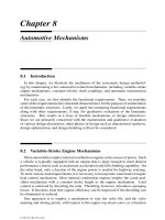
resulting contracted graph is shown in Figure 5.1.
FIGURE 5.1
A (2, 4) contracted graph.
Example 5.2 Enumeration of (3, 5) Contracted Graphs
We wish to enumerate all feasible contracted graphs having 3 vertices and 5 edges.
For v
c
= 3 and e
c
= 5,
˜
L = e
c
− v
c
+ 2 = 4. Equation (5.3) reduces to
d
1
+ d
2
+ d
3
= 10 ,
where 4 ≥ d
i
≥ 3. Solving the above equation by the procedure outlined in Ap-
pendix A yields d
1
= d
2
= 3 and d
3
= 4 as the only solution.
Substituting d
1
= d
2
= 3 and d
3
= 4 into Equation (5.1) results in a system of
3 equations in 3 unknowns:
a
1,2
+ a
1,3
= 3 ,
a
1,2
+ a
2,3
= 3 ,
a
1,3
+ a
2,3
= 4 , (5.5)
where 2 ≥ a
i,j
≥ 0. Solving Equation (5.5) yields a
1,2
= 1 and a
1,3
= a
2,3
= 2.
Hence, the adjacency matrix of the contracted graph is
A
c
=
012
102
220
.
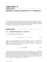
The corresponding graph is shown in Figure 5.2.
© 2001 by CRC Press LLC
FIGURE 5.2
A (3, 5) contracted graph.
Example 5.3 Enumeration of (4, 6) Contracted Graphs
We wish to enumerate all feasible contracted graphs with 4 vertices and 6 edges.
For v
c
= 4 and e
c
= 6,
˜
L = e
c
− v
c
+ 2 = 4. Hence, Equation (5.3) reduces to
d
1
+ d
2
+ d
3
+ d
4
= 12 , (5.6)
where 4 ≥ d
i
≥ 3. Solving Equation (5.6) by the procedure outlined in Appendix A
yields d
1
= d
2
= d
3
= d
4
= 3 as the only solution.
Substituting d
1
= d
2
= d
3
= d
4
= 3 into Equation (5.1) leads to a system of
4 equations in 6 unknowns:
a
1,2
+ a
1,3
+ a
1,4
= 3 , (5.7)
a
1,2
+ a
2,3
+ a
2,4
= 3 , (5.8)
a
1,3
+ a
2,3
+ a
3,4
= 3 , (5.9)
a
1,4
+ a
2,4
+ a
3,4
= 3 , (5.10)
where 2 ≥ a
i,j
≥ 0. Equation (5.7) contains 3 unknowns: a
1,2
,a
1,3
, and a
1,4
. At this
point, no distinction can be made among the 4 vertices. Without loss of generality,
we assume that a
1,2
≤ a
1,3
≤ a
1,4
. Note that solutions obtained in any other order
will simply lead to isomorphic graphs. Solving Equation (5.7) for a
1,2
,a
1,3
, and a
1,4
yields the following two solutions:
Solution a
1,2
a
1,3
a
1,4
1012
2111
Solution 1: Substituting a
1,2
= 0,a
1,3
= 1, and a
1,4
= 2 into Equations (5.8),
© 2001 by CRC Press LLC
(5.9), and (5.10) yields
a
2,3
+ a
2,4
= 3 , (5.11)
a
2,3
+ a
3,4
= 2 , (5.12)
a
2,4
+ a
3,4
= 1 . (5.13)
Solving Equations (5.11), (5.12), and (5.13), we obtain a
2,3
= 2,a
2,4
= 1, and
a
3,4
= 0. Thus, the adjacency matrix of the contracted graph is
A
c
=
0012
0021
1200
2100
.
The corresponding contracted graph is shown in Figure 5.3a.
FIGURE 5.3
Two (4, 6) contracted graphs.
Solution 2: Substituting a
1,2
= a
1,3
= a
1,4
= 1 into Equations (5.8), (5.9),
and (5.10) yields
a
2,3
+ a
2,4
= 2 , (5.14)
a
2,3
+ a
3,4
= 2 , (5.15)
a
2,4
+ a
3,4
= 2 . (5.16)
Solving Equations (5.14), (5.15), and (5.16), yields a
2,3
= a
2,4
= a
3,4
= 1. Hence,
the adjacency matrix of the contracted graph is
A
c
=
0111
1011
1101
1110
.
© 2001 by CRC Press LLC
The corresponding contracted graph is shown in Figure 5.3b.
The above procedure can be employed to enumerate contracted graphs having
several vertices and edges. An atlas of contracted graphs with up to four independent
loops and six vertices is given in Appendix B.
5.3 Enumeration of Conventional Graphs
Various algorithms for enumeration of conventional graphs have been developed.
Obviously the procedure described in the preceding section for enumeration of con-
tracted graphs can also be applied. However, direct enumeration of the adjacency
matrices becomes more involved with a larger number of vertices and edges. In this
section, we outline a systematic enumeration methodology developed by Woo [13].
The method is based on the concept of expansion from contracted graphs. The pro-
cedure involves the following steps:
S1. Given the number of links and the number of joints, solve Equations (4.12)
and (4.13) for all possible link assortments. We call each link assortment a
family.
S2. For each family, identify the corresponding contracted graphs from Appendix
B.
S3. Solve Equations (4.19) and (4.20) for all possible combinations of binary link
chains. We call each combination of binary link chains a branch.
S4. Permute the edges of each contracted graph with each combination of binary
link chains obtained in S3 in as many arrangements as possible. This is equiv-
alent to the problem of coloring the edges of a graph. Here, the concept of
similar edges can be employed to reduce the number of permutations.
S5. Eliminate those graphs that contain either parallel edges or partially locked
subchains.
S6. Check for graph isomorphisms. Note that only those graphs that belong to the
same family and same branch can possibly be isomorphic to one another.
In the following, we illustrate the procedure with an example.
Example 5.4 Enumeration of (6,8) Graphs
We wish to enumerate all possible (6, 8) graphs of planar one-dof kinematic chains.
For n = 6 and j = 8, we have
˜
L = 8 − 6 + 2 = 4. Equations (4.12) and (4.13)
© 2001 by CRC Press LLC
reduce to
n
2
+ n
3
+ n
4
= 6 , (5.17)
2n
2
+ 3n
3
+ 4n
4
= 16 . (5.18)
The minimal number of binary links is given by Equation (4.15),
n
2
≥ 2 .
Solving Equations (5.17) and (5.18) for nonnegative integers of n
i
by using Crossley’s
operator yields three families of link assortments:
Family n
2
n
3
n
4
2400 2 4 0
3210 3 2 1
4020 4 0 2
Next, we find the corresponding contracted graphs and solve Equations (4.19) and
(4.20) for all possible partitions of binary links. Since we are interested in F = 1
kinematic chains, the length of any binary link chain is bounded by Equation (4.22),
q ≤ 2 .
2400 family: For the 2400 family, the corresponding contracted graphs have v
c
=
6 − 2 = 4 vertices and e
c
= 8 − 2 = 6 edges. There are two contracted graphs with
4 vertices and 6 edges as shown in Figure 5.3.
With n
2
= 2, e
c
= 6, and q = 2, Equations (4.19) and (4.20) reduce to
b
1
+ 2b
2
= 2 , (5.19)
b
0
+ b
1
+ b
2
= 6 . (5.20)
Solving Equation (5.19) for nonnegative integers b
1
and b
2
, and then Equation (5.20)
for b
0
yields two branches of binary link chains:
Branch
b
0
b
1
b
2
1501
2420
For the first branch, we replace one of the six edges in each contracted graph shown
in Figure 5.3 with a binary link chain of length two. This is equivalent to a problem
of labeling one edge in one color and the remaining edges in another color. There are
six possible ways of labeling each contracted graph. Due to the existence of similar
edges, only two labelings of the graph shown in Figure 5.3a are nonisomorphic.
However, both labelings lead to a graph with parallel edges and, therefore, are not
© 2001 by CRC Press LLC
feasible. Since all edges in Figure 5.3b are similar, there is only one nonisomorphic
labeling of the graph as shown in Figure 5.4a.
Similarly, for the second branch, we replace two of the six edges with a binary
link chain of length one. This is equivalent to a problem of labeling two edges in
one color and the remaining edges in another color. There are 15 possible ways of
labeling each contracted graph. After eliminating those graphs that are isomorphic
or contain parallel edges, we obtain three labeled nonisomorphic graphs as shown in
Figure 5.4b.
FIGURE 5.4
Four nonisomorphic graphs derived from the 2400 family.
3210 family: For the 3210 family, the corresponding contracted graphs have v
c
=
6 − 3 = 3 vertices and e
c
= 8 − 3 = 5 edges. There is only one contracted graph
with 3 vertices and 5 edges as shown in Figure 5.2.
With n
2
= 3, e
c
= 5, and q = 2, Equations (4.19) and (4.20) reduce to
b
1
+ 2b
2
= 3 , (5.21)
b
0
+ b
1
+ b
2
= 5 . (5.22)
Solving Equation (5.21) for nonnegative integers b
1
and b
2
, and then Equation (5.22)
for b
0
yields two families of binary link chains:
© 2001 by CRC Press LLC
Branch b
0
b
1
b
2
1311
2230
For the first branch, we replace one of the edges in the contracted graph shown in
Figure 5.2 by a binary link chain of length one and another by a binary link chain of
length two. Note that there are two sets of two parallel edges. To avoid parallel edges
in the conventional graph, one in each set of two parallel edges must be replaced by
a binary link chain. In addition, the two sets of parallel edges are similar. Hence,
we obtain only one labeled nonisomorphic graph as shown in Figure 5.5a. For the
second branch, we replace three edges of the contracted graph each with a binary link
chain of length one. Again, at least one in each set of two parallel edges must be
replaced by a binary link chain. Thus, there are three possible ways of labeling the
edges. Due to similar edges, only two are nonisomorphic as shown in Figure 5.5b.
FIGURE 5.5
Three nonisomorphic graphs derived from the 3210 family.
4020 family: For the 4020 family, the corresponding contracted graphs have v
c
=
6 − 4 = 2 vertices and e
c
= 8 − 4 = 4 edges. There is only one contracted graph
with 2 vertices and 4 edges as shown in Figure 5.1.
© 2001 by CRC Press LLC
With n
2
= 4, e
c
= 4, and q = 2, Equations (4.19) and (4.20) reduce to
b
1
+ 2b
2
= 4 , (5.23)
b
0
+ b
1
+ b
2
= 4 . (5.24)
Solving Equation (5.23) for nonnegative integers b
1
and b
2
, and then Equation (5.24)
for b
0
yields three families of binary link chains:
Branch b
0
b
1
b
2
1202
2121
3040
For the first branch, we replace two of the four parallel edges of the contracted
graph shown in Figure 5.1 each with a binary link chain of length two. This produces
no feasible solutions because the resulting graphs always contain two parallel edges.
For the second branch, we replace two of the four edges of the contracted graph each
with a binary link chain of length one and one with a binary link chain of length two.
For the third branch, we replace all four edges of the contracted graph each with a
binary link chain of length one. As a result, we obtain two nonisomorphic graphs as
shown in Figure 5.6.
FIGURE 5.6
Two nonisomorphic graphs derived from the 4020 family.
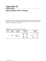
5.4 Atlas of Graphs of Kinematic Chains
Using the enumeration procedure described in the preceding section, graphs with
a given number of vertices and edges can be enumerated systematically. Appendix C
provides an atlas of graphs of kinematic chains with up to three independent loops
© 2001 by CRC Press LLC
and eight vertices. All graphs given in Appendix C are sketched in such a way that
the longest circuit forms the peripheral loop and the vertex of highest degree appears
on the top (or upper-left corner), provided that it does not cause crossing of the edges.
These graphs are arranged in the order of complexity according to the number of
loops, number of vertices, and length of peripheral loop. An atlas of all kinds of
graphs can be found in Read and Wilson [8].
5.5 Summary
We have shown that systematic algorithms using graph theory and combinatorial
analysis can be developed for enumeration of graphs of kinematic chains. Contracted
graphs with up to four loops and six vertices are provided in Appendix B. Based on
the concept of expansion from contracted graphs, an algorithm for enumeration of
conventional graphs is described. Conventional graphs with up to three independent
loops and eight vertices are tabulated in Appendix C. Using these atlases, an enormous
number of mechanisms can be developed by labeling the edges of the graphs according
to the available joint types and the choice of fixed links. This is the subject of the
following chapters.
References
[1] Chang, S.L. and Tsai, L.W., 1990, Topological Synthesis of Articulated Gear
Mechanisms, IEEE Journal of Robotics and Automation, 6, 1, 97–103.
[2] Chatterjee, G. and Tsai, L.W., 1994, Enumeration of Epicyclic-Type Automatic
Transmission Gear Trains, SAE 1994 Trans., Journal of Passenger Cars, Sec. 6,
103, 1415–1426.
[3] Crossley, F.R.E., 1964, A Contribution to Grübler’s Theory in Number Synthe-
sis of Plane Mechanisms, ASME Journal of Engineering for Industry, Series B,
86, 1–8.
[4] Crossley, F.R.E., 1965, The Permutation of Kinematic Chains of Eight Members
or Less from the Graph-Theoretic Viewpoint, in Developments in Theoretical
and Applied Mechanics, Vol. 2, Pergamon Press, Oxford, 467–486.
[5] Davies, T.H., 1968, An Extension of Manolescu’s Classification of Planar Kine-
matic Chains and Mechanisms of Mobility m ≥ 1, Using Graph Theory, Journal
of Mechanisms and Machine Theory, 4, 87–100.
© 2001 by CRC Press LLC
[6] Freudenstein, F., 1967, The Basic Concept of Polya’s Theory of Enumeration
with Application to the Structural Classification of Mechanisms, Journal of
Mechanisms, 3, 275–290.
[7] Pólya, G., 1938, Kombinatorische Anzahlbestimmungen
´
f’ur Gruppen,
Graphen und Chemische Verbindungen, Acta Math., 68, 145–254.
[8] Read, R.C. and Wilson, R.J., 1998, An Atlas of Graphs, Oxford University
Press, New York.
[9] Sohn, W. 1987, A Computer-Aided Approach to the Creative Design of Mech-
anisms, Ph.D. Dissertation, Dept. of Mechanical Engineering, Columbia Uni-
versity, New York, NY.
[10] Sohn, W. and Freudenstein, F., 1986, An Application of Dual Graphs to the Au-
tomatic Generation of the Kinematic Structures of Mechanism, ASME Journal
of Mechanisms, Transmissions, and Automation in Design, 108, 3, 392–398.
[11] Tuttle, E.R., Peterson, S.W., and Titus, J.E., 1989, Enumeration of Basic Kine-
matic Chains Using the Theory of Finite Groups, ASME Journal of Mechanisms,
Transmissions, and Automation in Design, 111, 4, 498–503.
[12] Tuttle, E.R., Peterson, S.W., and Titus, J.E., 1989, Further Application of Group
Theory to the Enumeration and Structural Analysis of Basic Kinematic Chains,
ASME Journal of Mechanisms, Transmissions, and Automation in Design, 111,
4, 494–497.
[13] Woo, L.S., 1967, Type Synthesis of Plane Linkages, ASME Journal of Engi-
neering for Industry, Series B, 89, 159–172.
[14] Yan, H.S., 1998, Creative Design of Mechanical Devices, Springer-Verlag,
Singapore.
Exercises
5.1 Enumerate all the feasible (3, 6) contracted graphs.
5.2 Enumerate all the feasible (4, 7) contracted graphs.
5.3 Enumerate all the feasible (5, 7) conventional graphs of planar kinematic chains
using Woo’s method.
5.4 Enumerate all the feasible (6, 8) conventional graphs of planar kinematic chains
using Woo’s method.
5.5 Enumerate all the feasible (7, 9) conventional graphs of planar kinematic chains
using Woo’s method.
© 2001 by CRC Press LLC