(McGraw-Hill) (Instructors Manual) Electric Machinery Fundamentals 4th Edition Episode 1 Part 7 doc
Bạn đang xem bản rút gọn của tài liệu. Xem và tải ngay bản đầy đủ của tài liệu tại đây (657.5 KB, 20 trang )
115
(a) This generator is Y-connected, so
LA
II= . At rated conditions, the line and phase current in this
generator is
(
)
1000 kVA
251 A
3 3 2300 V
AL
L
P
II
V
== = = at an angle of –36.87
°
The phase voltage of this machine is
/
31328 V
T
VV
φ
==
. The internal generated voltage of the machine
is
AAASA
RjX
φ
=+ +EV I I
(
)
(
)
(
)
(
)
1328 0 0.15 251 36.87 A 1.1 251 36.87 A
A
j=∠°+ Ω∠− °+ Ω∠− °E
1537 7.4 V
A
=∠°E
The input power to this generator is equal to the output power plus losses. The rated output power is
()()
OUT
1000 kVA 0.8 800 kWP ==
()( )
2
2
CU
3 3 251 A 0.15 28.4 kW
AA
PIR== Ω=
F&W
24 kWP =
core
18 kWP =
stray
(assumed 0)P =
IN OUT CU F&W core stray
870.4 kWPP PP P P=++++=
OUT
IN
800 kW
100% 100% 91.9%
870.4 kW
P
P
η =× = × =
(b) If the generator is loaded to rated kVA with lagging loads, the phase voltage is 1328 0 V
φ
= ∠ °V and
the internal generated voltage is 1537 7.4 V
A
E =∠°. Therefore, the phase voltage at no-load would be
1537 0 VV
φ
=∠°. The voltage regulation would be:
1537 1328
VR 100% 15.7%
1328
−
=×=
(c) If the generator is loaded to rated kVA with leading loads, the phase voltage is 1328 0 V
φ
= ∠ °V and
the internal generated voltage is
AAASA
RjX
φ
=+ +EV I I
()( )()( )
1328 0 0.15 251 36.87 A 1.1 251 36.87 A
A
jE =∠°+ Ω∠°+ Ω∠ °
1217 11.5 V
A
E =∠°
The voltage regulation would be:
1217 1328
VR 100% 8.4%
1328
−
=×=−
(d) If the generator is loaded to rated kVA at unity power factor, the phase voltage is
1328 0 V
φ
= ∠ °V
and the internal generated voltage is
AAASA
RjX
φ
=+ +EV I I
116
()()()()
1328 0 0.15 251 0 A 1.1 251 0 A
A
jE =∠°+ Ω∠°+ Ω∠°
1393 11.4 V
A
E =∠°
The voltage regulation would be:
1393 1328
VR 100% 4.9%
1328
−
=×=
(e) For this problem, we will assume that the terminal voltage is adjusted to 2300 V at no load
conditions, and see what happens to the voltage as load increases at 0.8 lagging, unity, and 0.8 leading
power factors. Note that the maximum current will be 251 A in any case. A phasor diagram representing
the situation at lagging power factor is shown below:
I
A
V
φ
E
A
θ
δ
θ
θ
I
A
R
A
jX
S
I
A
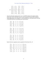
By the Pythagorean Theorem,
()
()
2
2
2
cos sin cos sin
AAASA SAAS
E V RI XI XI RI
φ
θθ θθ
=+ + + −
()
2
2
cos sin cos sin
ASA AS AA SA
VEXI RI RI XI
φ
θθ θ θ
=− − − −
A phasor diagram representing the situation at leading power factor is shown below:
I
A
V
φ
E
A
θ
δ
θ
θ
I
A
R
A
jX
S
I
A
By the Pythagorean Theorem,
(
)
()
2
2
2
cos sin cos sin
AAASA SAAS
E V RI XI XI RI
φ
θθ θθ
=+ − + +
()
2
2
cos sin cos sin
ASA AS AA SA
VEXI RI RI XI
φ
θθ θ θ
=− + − +
A phasor diagram representing the situation at unity power factor is shown below:
I
A
V
φ
E
A
δ
I
A
R
A
jX
S
I
A
117
By the Pythagorean Theorem,
(
)
2
22
ASA
EV XI
φ
=+
()
2
2
ASA
VEXI
φ
=−
The MATLAB program is shown below takes advantage of this fact.
% M-file: prob5_4e.m
% M-file to calculate and plot the terminal voltage
% of a synchronous generator as a function of load
% for power factors of 0.8 lagging, 1.0, and 0.8 leading.
% Define values for this generator
EA = 1328; % Internal gen voltage
I = 0:2.51:251; % Current values (A)
R = 0.15; % R (ohms)
X = 1.10; % XS (ohms)
% Calculate the voltage for the lagging PF case
VP_lag = sqrt( EA^2 - (X.*I.*0.8 - R.*I.*0.6).^2 )
- R.*I.*0.8 - X.*I.*0.6;
VT_lag = VP_lag .* sqrt(3);
% Calculate the voltage for the leading PF case
VP_lead = sqrt( EA^2 - (X.*I.*0.8 + R.*I.*0.6).^2 )
- R.*I.*0.8 + X.*I.*0.6;
VT_lead = VP_lead .* sqrt(3);
% Calculate the voltage for the unity PF case
VP_unity = sqrt( EA^2 - (X.*I).^2 );
VT_unity = VP_unity .* sqrt(3);
% Plot the terminal voltage versus load
plot(I,abs(VT_lag),'b-','LineWidth',2.0);
hold on;
plot(I,abs(VT_unity),'k ','LineWidth',2.0);
plot(I,abs(VT_lead),'r ','LineWidth',2.0);
title ('\bfTerminal Voltage Versus Load');
xlabel ('\bfLoad (A)');
ylabel ('\bfTerminal Voltage (V)');
legend('0.8 PF lagging','1.0 PF','0.8 PF leading');
axis([0 260 1500 2500]);
grid on;
hold off;
The resulting plot is shown below:
118
5-5. Assume that the field current of the generator in Problem 5-2 has been adjusted so that it supplies rated
voltage when loaded with rated current at unity power factor. (You may ignore the effects of
A
R when
answering these questions.)
(a) What is the torque angle
δ
of the generator when supplying rated current at unity power factor?
(b) When this generator is running at full load with unity power factor, how close is it to the static stability
limit of the machine?
S
OLUTION
(a) The torque
δ
angle can be found by calculating
A
E
:
AAASA
RjX
φ
=+ +EV I I
()()()()
1328 0 0.15 251 0 A 1.1 251 0 A
A
jE =∠°+ Ω∠°+ Ω∠°
1393 11.4 V
A
E =∠°
Thus the torque angle
δ
= 11.4
°
.
(b) The static stability limit occurs at
°= 90
δ
. This generator is a very long way from that limit. If we
ignore the internal resistance of the generator, the output power will be given by
3
sin
A
S
VE
P
X
φ
δ
=
and the output power is proportional to
sin
δ
. Since
sin 11.4 0.198°=
, and
sin 90 1.00°=
, the static
stability limit is about 5 times the current output power of the generator.
5-6. A 480-V 400-kVA 0.85-PF-lagging 50-Hz four-pole
∆
-connected generator is driven by a 500-hp diesel
engine and is used as a standby or emergency generator. This machine can also be paralleled with the
normal power supply (a very large power system) if desired.
(a) What are the conditions required for paralleling the emergency generator with the existing power
system? What is the generator’s rate of shaft rotation after paralleling occurs?
119
(b) If the generator is connected to the power system and is initially floating on the line, sketch the resulting
magnetic fields and phasor diagram.
(c) The governor setting on the diesel is now increased. Show both by means of house diagrams and by
means of phasor diagrams what happens to the generator. How much reactive power does the generator
supply now?
(d) With the diesel generator now supplying real power to the power system, what happens to the generator
as its field current is increased and decreased? Show this behavior both with phasor diagrams and with
house diagrams.
S
OLUTION
(a) To parallel this generator to the large power system, the required conditions are:
1. The generator must have the
same voltage as the power system.
2. The
phase sequence of the oncoming generator must be the same as the phase sequence of the
power system.
3. The
frequency of the oncoming generator should be slightly higher than the frequency of the
running system.
4. The circuit breaker connecting the two systems together should be shut when the above conditions
are met and the generator is
in phase with the power system.
After paralleling, the generator’s shaft will be rotating at
()
120 50 Hz
120
1500 r/min
4
e
m
f
n
P
== =
(b) The magnetic field and phasor diagrams immediately after paralleling are shown below:
I
A
V
φ
E
A
jX
S
I
A
B
R
B
S
B
net
(c) When the governor setpoints on the generator are increased, the emergency generator begins to supply
more power to the loads, as shown below:
I
A
V
φ
E
A
jX
S
I
A
f
e
P
1
P
2
P
sys
P
G
Note that as the load increased with
A
E
constant, the generator began to consume a small amount of
reactive power.
(d) With the generator now supplying power to the system, an increase in field current increases the
reactive power supplied to the loads, and a decrease in field current decreases the reactive power supplied
to the loads.
120
V
φ
E
A
1
jX
S
I
A
Q
sys
Q
G
Q
2
Q
1
Q
3
E
A
2
E
A
3
I
A
3
I
A
2
I
A
1
V
φ
E
A
1
jX
S
I
A
Q
sys
Q
G
Q
2
Q
1
E
A
2
I
A
2
I
A
1
V
T
V
T
5-7. A 13.8-kV 10-MVA 0.8-PF-lagging 60-Hz two-pole Y-connected steam-turbine generator has a
synchronous reactance of 12 Ω per phase and an armature resistance of 1.5 Ω per phase. This generator is
operating in parallel with a large power system (infinite bus).
(a) What is the magnitude of E
A
at rated conditions?
(b) What is the torque angle of the generator at rated conditions?
(c) If the field current is constant, what is the maximum power possible out of this generator? How much
reserve power or torque does this generator have at full load?
(d) At the absolute maximum power possible, how much reactive power will this generator be supplying or
consuming? Sketch the corresponding phasor diagram. (Assume
I
F
is still unchanged.)
S
OLUTION
(a) The phase voltage of this generator at rated conditions is
13,800 V
7967 V
3
V
φ
==
The armature current per phase at rated conditions is
()
10,000,000 VA
418 A
3 3 13,800 V
A
T
S
I
V
== =
Therefore, the internal generated voltage at rated conditions is
AAASA
RjXEV I I
φ
=+ +
()( )( )( )
7967 0 1.5 418 36.87 A 12.0 418 36.87 A
A
jE =∠°+Ω∠− °+ Ω∠− °
12,040 17.6 V
A
E =∠°
121
The magnitude of
A
E is 12,040 V.
(b) The torque angle of the generator at rated conditions is
δ
= 17.6°.
(c) Ignoring
A
R
, the maximum output power of the generator is given by
()( )
MAX
3
3 7967 V 12,040 V
24.0 MW
12
A
S
VE
P
X
φ
== =
Ω
The power at maximum load is 8 MW, so the maximum output power is three times the full load output
power.
(d) The phasor diagram at these conditions is shown below:
jX
S
I
A
V
φ
I
A
E
A
I
A
R
A
Under these conditions, the armature current is
12,040 90 V - 7967 0 V
1194 40.6 A
1.5 12.0
A
A
AS
RjX j
EV
I
φ
−
∠° ∠°
== =∠°
++Ω
The reactive power produced by the generator at this point is
()()( )
3 sin 3 7967 V 1194 A sin 0 40.6 18.6 MVAR
A
QVI
φ
θ
== °−°=−
The generator is actually consuming reactive power at this time.
5-8. A 480-V, 100-kW, two-pole, three-phase, 60-Hz synchronous generator’s prime mover has a no-load speed
of 3630 r/min and a full-load speed of 3570 r/min. It is operating in parallel with a 480-V, 75-kW, four-
pole, 60-Hz synchronous generator whose prime mover has a no-load speed of 1800 r/min and a full-load
speed of 1785 r/min. The loads supplied by the two generators consist of 100 kW at 0.85 PF lagging.
(a) Calculate the speed droops of generator 1 and generator 2.
(b) Find the operating frequency of the power system.
(c) Find the power being supplied by each of the generators in this system.
(d) If V
T
is 460 V, what must the generator’s operators do to correct for the low terminal voltage?
S
OLUTION
The no-load frequency of generator 1 corresponds to a frequency of
()()
nl1
3630 r/min 2
60.5 Hz
120 120
m
nP
f == =
The full-load frequency of generator 1 corresponds to a frequency of
122
()()
fl1
3570 r/min 2
59.5 Hz
120 120
m
nP
f
== =
The no-load frequency of generator 2 corresponds to a frequency of
()()
nl2
1800 r/min 4
60.00 Hz
120 120
m
nP
f == =
The full-load frequency of generator 2 corresponds to a frequency of
()()
fl2
1785 r/min 4
59.50 Hz
120 120
m
nP
f == =
(a) The speed droop of generator 1 is given by
nl fl
1
fl
3630 r/min 3570 r/min
SD 100% 100% 1.68%
3570 r/min
nn
n
−−
=×= ×=
The speed droop of generator 2 is given by
nl fl
2
fl
1800 r/min 1785 r/min
SD 100% 100% 0.84%
1785 r/min
nn
n
−−
=×= ×=
(b) The power supplied by generator 1 is given by
()
1 1 nl1 sysP
Ps f f=−
and the power supplied by generator 1 is given by
()
2 2 nl2 sysP
Ps f f=−
The power curve’s slope for generator 1 is
1
nl fl
0.1 MW
0.1 MW/Hz
60.5 Hz 59.5 Hz
P
P
s
ff
== =
−−
The power curve’s slope for generator 1 is
2
nl fl
0.075 MW
0.150 MW/Hz
60.00 Hz 59.50 Hz
P
P
s
ff
== =
−−
The no-load frequency of generator 1 is 60.5 Hz and the no-load frequency of generator 2 is 60 Hz. The
total power that they must supply is 100 kW, so the system frequency can be found from the equations
LOAD 1 2
PPP=+
()()
LOAD 1 nl1 sys 2 nl2 sysPP
Psffsff=−+−
()
()
()
()
sys sys
100 kW 0.1 MW/Hz 60.5 Hz 0.15 MW/Hz 60.0 Hzff=−+ −
() ()
sys sys
100 kW 6050 kW 0.10 MW/Hz 9000 kW 0.15 MW/Hzff=− +−
()
sys
0.25 MW/Hz 6050 kW 9000 kW 100 kWf =+−
sys
14,950 kW
59.8 Hz
0.25 MW/Hz
f ==
(c) The power supplied by generator 1 is
123
()
()( )
11nl1sys
0.1 MW/Hz 60.5 Hz 59.8 Hz 70 kW
P
Ps f f=−= − =
The power supplied by generator 2 is
()
()( )
22nl2sys
0.15 MW/Hz 60.0 Hz 59.8 Hz 30 kW
P
Ps f f=−= − =
(d) If the terminal voltage is 460 V, the operators of the generators must increase the field currents on
both generators simultaneously. That action will increase the terminal voltages of the system without
changing the power sharing between the generators.
5-9.
Three physically identical synchronous generators are operating in parallel. They are all rated for a full
load of 3 MW at 0.8 PF lagging. The no-load frequency of generator A is 61 Hz, and its speed droop is 3.4
percent. The no-load frequency of generator B is 61.5 Hz, and its speed droop is 3 percent. The no-load
frequency of generator C is 60.5 Hz, and its speed droop is 2.6 percent.
(a) If a total load consisting of 7 MW is being supplied by this power system, what will the system
frequency be and how will the power be shared among the three generators?
(b) Create a plot showing the power supplied by each generator as a function of the total power supplied to
all loads (you may use MATLAB to create this plot). At what load does one of the generators exceed
its ratings? Which generator exceeds its ratings first?
(c) Is this power sharing in (a) acceptable? Why or why not?
(d) What actions could an operator take to improve the real power sharing among these generators?
S
OLUTION
(a) Speed droop is defined as
nl fl nl fl
fl fl
SD 100% 100%
nn f f
nf
−−
=×=×
so
nl
fl
SD
1
100
f
f =
+
Thus, the full-load frequencies of generators A, B, and C are
nl,A
fl,A
A
61 Hz
59.0 Hz
SD 3.4
11
100 100
f
f ===
++
nl,B
fl,B
B
61.5 Hz
59.71 Hz
SD 3.0
11
100 100
f
f ===
++
nl,C
fl,C
C
60.5 Hz
58.97 Hz
SD 2.6
11
100 100
f
f ===
++
and the slopes of the power-frequency curves are:
3 MW
1.5 MW/Hz
2 Hz
PA
S ==
3 MW
1.676 MW/Hz
1.79 Hz
PB
S ==
3 MW
1.961 MW/Hz
1.53 Hz
PC
S ==
124
(a) The total load is 7 MW, so the system frequency is
()()()
LOAD nlA sys nlB sys nlC sysPA PB PC
P sffsffsff=−+−+−
(
)
()
(
)
()
(
)
()
sys sys sys
7 MW 1.5 61.0 1.676 61.5 1.961 60.5fff=−+ −+ −
sys sys sys
7 MW 91.5 1.5 103.07 1.676 118.64 1.961fff=−+− +−
sys
5.137 306.2f =
sys
59.61 Hzf =
The power supplied by each generator will be
()
()( )
nlA sys
1.5 MW/Hz 61.0 Hz 59.61 Hz 2.09 MW
APA
Psf f=−= − =
()
()( )
nlB sys
1.676 MW/Hz 61.5 Hz 59.61 Hz 3.17 MW
BPB
Psf f=−= − =
()
()( )
nlC sys
1.961 MW/Hz 60.5 Hz 59.61 Hz 1.74 MW
CPC
Ps f f=−= − =
(b) The equation in part (a) can be re-written slightly to express system frequency as a function of load.
()
()
()
()
()
()
LOAD sys sys sys
1.5 61.0 1.676 61.5 1.961 60.5Pf f f=−+ −+ −
LOAD sys sys sys
91.5 1.5 103.07 1.676 118.64 1.961Pf f f=− + − + −
sys LOAD
5.137 313.2fP=−
LOAD
sys
313.2
5.137
P
f
−
=
A MATLAB program that uses this equation to determine the power sharing among the generators as a
function of load is shown below:
% M-file: prob5_9b.m
% M-file to calculate and plot the power sharing among
% three generators as a function of load.
% Define values for this generator
fnlA = 61.0; % No-load freq of Gen A
fnlB = 61.5; % No-load freq of Gen B
fnlC = 60.5; % No-load freq of Gen C
spA = 1.5; % Slope of Gen A (MW/Hz)
spB = 1.676; % Slope of Gen B (MW/Hz)
spC = 1.961; % Slope of Gen C (MW/Hz)
Pload = 0:0.05:10; % Load in MW
% Calculate the system frequency
fsys = (313.2 - Pload) ./ 5.137;
% Calculate the power of each generator
PA = spA .* ( fnlA - fsys);
PB = spB .* ( fnlB - fsys);
PC = spC .* ( fnlC - fsys);
% Plot the power sharing versus load
plot(Pload,PA,'b-','LineWidth',2.0);
125
hold on;
plot(Pload,PB,'k ','LineWidth',2.0);
plot(Pload,PC,'r ','LineWidth',2.0);
plot([0 10],[3 3],'k','LineWidth',1.0);
plot([0 10],[0 0],'k:');
title ('\bfPower Sharing Versus Total Load');
xlabel ('\bfTotal Load (MW)');
ylabel ('\bfGenerator Power (MW)');
legend('Generator A','Generator B','Generator C','Power Limit');
grid on;
hold off;
The resulting plot is shown below:
This plot reveals that there are power sharing problems both for high loads and for low loads. Generator B
is the first to exceed its ratings as load increases. Its rated power is reached at a total load of 6.45 MW.
On the other hand, Generator C gets into trouble as the total load is reduced. When the total load drops to
2.4 MW, the direction of power flow reverses in Generator C.
(c) The power sharing in (a) is not acceptable, because Generator 2 has exceeded its power limits.
(d) To improve the power sharing among the three generators in (a) without affecting the operating
frequency of the system, the operator should decrease the governor setpoints on Generator B while
simultaneously increasing them in Generators A and C.
5-10. A paper mill has installed three steam generators (boilers) to provide process steam and also to use some its
waste products as an energy source. Since there is extra capacity, the mill has installed three 5-MW
turbine generators to take advantage of the situation. Each generator is a 4160-V 6250-kVA 0.85-PF-
lagging two-pole Y-connected synchronous generator with a synchronous reactance of 0.75
Ω
and an
armature resistance of 0.04
Ω
. Generators 1 and 2 have a characteristic power-frequency slope
s
P
of 2.5
MW/Hz, and generators 2 and 3 have a slope of 3 MW/Hz.
(a) If the no-load frequency of each of the three generators is adjusted to 61 Hz, how much power will the
three machines be supplying when actual system frequency is 60 Hz?
126
(b) What is the maximum power the three generators can supply in this condition without the ratings of one
of them being exceeded? At what frequency does this limit occur? How much power does each
generator supply at that point?
(c) What would have to be done to get all three generators to supply their rated real and reactive powers at
an overall operating frequency of 60 Hz?
(d) What would the internal generated voltages of the three generators be under this condition?
S
OLUTION
(a) If the system frequency is 60 Hz and the no-load frequencies of the generators are 61 Hz, then the
power supplied by the generators will be
()
()( )
11nl1sys
2.5 MW/Hz 61 Hz 60 Hz 2.5 MW
P
Ps f f=−= −=
()
(
)
(
)
2 2 nl2 sys
2.5 MW/Hz 61 Hz 60 Hz 2.5 MW
P
Ps f f=−= −=
()
(
)
(
)
3 3 nl3 sys
3.0 MW/Hz 61 Hz 60 Hz 3.0 MW
P
Ps f f=−= −=
Therefore the total power supplied by the generators is 8 MW.
(b) The maximum power supplied by any one generator is (6250 kVA)(0.85) = 5.31 MW. Generator 3
will be the first machine to reach that limit. Generator 3 will supply this power at a frequency of
()
()
sys
5.31 MW 3.0 MW/Hz 61 Hz f=−
Hz23.59
sys
=f
At this point the power supplied by Generators 1 and 2 is
()
()( )
12 1nl1sys
2.5 MW/Hz 61 Hz 59.23 Hz 4.425 MW
P
PPs f f== − = − =
The total power supplied by the generators at this condition is 14.16 MW.
(c) To get each of the generators to supply 5.31 MW at 60 Hz, the no-load frequencies of Generator 1
and Generator 2 would have to be adjusted to 62.12 Hz, and the no-load frequency of Generator 3 would
have to be adjusted to 61.77 Hz. The field currents of the three generators must then be adjusted to get
them supplying a power factor of 0.85 lagging. At that point, each generator will be supplying its rated
real and reactive power.
(d) Under the conditions of part (c), which are the rated conditions of the generators, the internal
generated voltage would be given by
AAASA
RjXEV I I
φ
=+ +
The phase voltage of the generators is 4160 V /
3
= 2402 V, and since the generators are Y-connected,
their rated current is
()
6250 kVA
867 A
3 3 4160 V
AL
T
S
II
V
== = =
The power factor is 0.85 lagging, so 867 31.8 A
A
I =∠− °. Therefore,
AAASA
RjXEV I I
φ
=+ +
()()()()
2402 0 0.04 867 31.8 A 0.75 867 31.8 A
A
jE =∠°+ Ω∠−°+ Ω∠−°
127
2825 10.9 V
A
E =∠°
Problems 5-11 to 5-21 refer to a two-pole Y-connected synchronous generator rated at 470 kVA, 480 V, 60 Hz,
and 0.85 PF lagging. Its armature resistance
R
A
is 0.016 Ω. The core losses of this generator at rated conditions
are 7 kW, and the friction and windage losses are 8 kW. The open-circuit and short-circuit characteristics are
shown in Figure P5-2.
128
Note: An electronic version of the saturated open circuit characteristic can be found
in file p52_occ.dat, and an electronic version of the air-gap characteristic
can be found in file
p52_ag_occ.dat
. These files can be used with
MATLAB programs. Column 1 contains field current in amps, and column 2
contains open-circuit terminal voltage in volts. An electronic version of the
short circuit characteristic can be found in file
p52_scc.dat
. Column 1
contains field current in amps, and column 2 contains short-circuit terminal
current in amps.
5-11.
(a) What is the saturated synchronous reactance of this generator at the rated conditions? (b) What is the
unsaturated synchronous reactance of this generator? (c) Plot the saturated synchronous reactance of this
generator as a function of load.
S
OLUTION
(a) The rated armature current for this generator is
()
470 kVA
565 A
3 3 480 V
AL
T
S
II
V
== = =
The field current required to produce this much short-circuit current may be read from the SCC. It is 0.534
A
3
. The open circuit voltage at 0.532 A is 880 V
4
, so the open-circuit phase voltage (=
A
E ) is 880/
3
=
508 V. The approximate saturated synchronous reactance
S
X is
3
If you have MATLAB available, you can use the file
p52_scc.dat
and the
interp1
function to look up this
value as shown below. Note that column 1 of p52_scc contains field current, and column 2 contains short-circuit
terminal current.
load p52_scc.dat
if = interp1(p52_scc(:,2),p52_scc(:,1),565)
if =
129
508 V
0.899
565 A
S
X ==Ω
(b) The unsaturated synchronous reactance
Su
X
is the ratio of the air-gap line to the SCC. This is a
straight line, so we can determine its value by comparing the ratio of the air-gap voltage to the short-circuit
current at any given field current. For example, at
F
I = 0.50 A, the air-gap line voltage is 1040 V, and the
SCC is 532 A.
()
1040 V / 3
1.13
532 A
Su
X ==Ω
(c) This task can best be performed with MATLAB. The open-circuit characteristic is available in a file
called
p52_occ.dat, and the short-circuit characteristic is available in a file called p52_scc.dat.
Each of these files are organized in two columns, where the first column is field current and the second
column is either open-circuit terminal voltage or short-circuit current. A program to read these files and
calculate and plot
S
X
is shown below.
% M-file: prob5_11c.m
% M-file to calculate and plot the saturated
% synchronous reactance of a synchronous
% generator.
% Load the open-circuit characteristic. It is in
% two columns, with the first column being field
% current and the second column being terminal
% voltage.
load p52.occ;
if_occ = p52(:,1);
vt_occ = p52(:,2);
% Load the short-circuit characteristic. It is in
% two columns, with the first column being field
% current and the second column being line current
% (= armature current)
load p52.scc;
if_scc = p52(:,1);
ia_scc = p52(:,2);
% Calculate Xs
if = 0.001:0.02:1; % Current steps
vt = interp1(if_occ,vt_occ,If); % Terminal voltage
ia = interp1(if_scc,ia_scc,If); % Current
Xs = (vt ./ sqrt(3)) ./ ia;
0.534
4
If you have MATLAB available, you can use the file
p52_occ.dat
and the
interp1
function to look up this
value as shown below. Note that column 1 of p52_occ contains field current, and column 2 contains open-circuit
terminal voltage.
load p52_occ.dat
vt = interp1(p52_occ(:,1),p52_occ(:,2),0.534)
vt =
880.400
130
% Plot the synchronous reactance
figure(1)
plot(If,Xs,'LineWidth',2.0);
title ('\bfSaturated Synchronous Reactance \itX_{s} \rm');
xlabel ('\bfField Current (A)');
ylabel ('\bf\itX_{s} \rm\bf(\Omega)');
grid on;
The resulting plot is:
5-12. (a) What are the rated current and internal generated voltage of this generator? (b) What field current
does this generator require to operate at the rated voltage, current, and power factor?
S
OLUTION
(a) The rated line and armature current for this generator is
()
470 kVA
565 A
3 3 480 V
AL
T
S
II
V
== = =
The power factor is 0.85 lagging, so
565.3 31.8 A
A
I =∠−°
. The rated phase voltage is
V
φ
= 480 V /
3
= 277 V. The saturated synchronous reactance at rated conditions was found to be 0.450
Ω
in the previous
problem. Therefore, the internal generated voltage is
AAASA
RjXEV I I
φ
=+ +
()( )()( )
277 0 0.016 565.3 31.8 A 0.899 565.3 31.8 A
A
j=∠°+ Ω ∠− °+ Ω ∠− °E
509 30.5 V
A
E =∠°
(b) This internal generated voltage corresponds to a no-load terminal voltage of
()
3509 = 881 V.
From the open-circuit characteristic, the required field current would be 0.535 A.
5-13. What is the voltage regulation of this generator at the rated current and power factor?
S
OLUTION
The voltage regulation is
131
,nl ,fl
,fl
881 480
VR 100% 100% 83.5%
480
TT
T
VV
V
−
−
=×=×=
5-14. If this generator is operating at the rated conditions and the load is suddenly removed, what will the
terminal voltage be?
S
OLUTION
From the above calculations,
T
V will be 881 V.
5-15. What are the electrical losses in this generator at rated conditions?
S
OLUTION
The electrical losses are
()( )
2
2
CU
3 3 565 A 0.016 15.3 kW
AA
PIR== Ω=
5-16. If this machine is operating at rated conditions, what input torque must be applied to the shaft of this
generator? Express your answer both in newton-meters and in pound-feet.
S
OLUTION
To get the applied torque, we must know the input power. The input power to this generator is
equal to the output power plus losses. The rated output power and the losses are
()()
OUT
470 kVA 0.85 400 kWP ==
()( )
2
2
CU
3 3 565 A 0.016 15.3 kW
AA
PIR== Ω=
F&W
8 kWP =
core
7 kWP =
stray
(assumed 0)P =
IN OUT CU F&W core stray
430.3 kWPP PP P P=++++=
Therefore, the applied torque is
()
IN
APP
430.3 kW
2280 N m
2 rad 1 min
1800 r/min
1 r 60 s
m
P
τ
π
ω
== = ⋅
or
(
)
APP
7.04 430.3 kW
7.04
1680 lb ft
1800 r/min
m
P
n
τ
== =⋅
5-17.
What is the torque angle
δ
of this generator at rated conditions?
S
OLUTION
From the calculations in Problem 5-12,
δ
= 30.5°.
5-18. Assume that the generator field current is adjusted to supply 480 V under rated conditions. What is the
static stability limit of this generator? (Note: You may ignore
A
R to make this calculation easier.) How
close is the full-load condition of this generator to the static stability limit?
S
OLUTION
At rated conditions, 509 30.5 V
A
=∠°E . Therefore, the static stability limit is
()()
MAX
3
3277 V 509 V
471 kW
0.899
A
S
VE
P
X
φ
== =
Ω
The full-load rated power of this generator is reasonably close to the static stability limit. Normal
generators would have more margin than this.
132
5-19. Assume that the generator field current is adjusted to supply 480 V under rated conditions. Plot the power
supplied by the generator as a function of the torque angle
δ
. (Note: You may ignore
A
R to make this
calculation easier.)
S
OLUTION
We will again ignore
A
R to make this calculation easier. The power supplied by the generator is
()()
()
3
3 277 V 509 V
sin sin 471 kW sin
0.899
A
G
S
VE
P
X
φ
δδδ
== =
Ω
The power supplied as a function of the torque angle
δ
may be plotted using a simple MATLAB program:
% M-file: prob5_19.m
% M-file to plot the power output of a
% synchronous generator as a function of
% the torque angle.
% Calculate Xs
delta = (0:1:90); % Torque angle (deg)
Pout = 561 .* sin(delta * pi/180); % Pout
% Plot the output power
figure(1)
plot(delta,Pout,'LineWidth',2.0);
title ('\bfOutput power vs torque angle \delta');
xlabel ('\bfTorque angle \delta (deg)');
ylabel ('\bf\itP_{OUT} \rm\bf(kW)');
grid on;
The resulting plot is:
5-20. Assume that the generator’s field current is adjusted so that the generator supplies rated voltage at the rated
load current and power factor. If the field current and the magnitude of the load current are held constant,
how will the terminal voltage change as the load power factor varies from 0.85 PF lagging to 0.85 PF
133
leading? Make a plot of the terminal voltage versus the impedance angle of the load being supplied by this
generator.
S
OLUTION
If the field current is held constant, then the magnitude of
A
E will be constant, although its
angle
δ
will vary. Also, the magnitude of the armature current is constant. Since we also know
A
R ,
S
X ,
and the current angle
θ
, we know enough to find the phase voltage
φ
V
, and therefore the terminal voltage
T
V
. At lagging power factors,
φ
V
can be found from the following relationships:
I
A
V
φ
E
A
θ
δ
θ
θ
I
A
R
A
jX
S
I
A
By the Pythagorean Theorem,
()
()
222
sincossincos
θθθθ
φ
SAASASAAA
IRIXIXIRVE −+++=
()
θθθθ
φ
sincossincos
22
ASAASAASA
IXIRIRIXEV −−−−=
At unity power factor,
φ
V can be found from the following relationships:
I
A
V
φ
E
A
δ
I
A
R
A
jX
S
I
A
By the Pythagorean Theorem,
(
)
2
22
ASA
EV XI
φ
=+
()
22
ASA
IXEV −=
φ
At leading power factors,
φ
V can be found from the following relationships:
I
A
V
φ
E
A
θ
δ
θ
θ
I
A
R
A
jX
S
I
A
By the Pythagorean Theorem,
134
()
()
222
sincossincos
θθθθ
φ
SAASASAAA
IRIXIXIRVE ++−+=
()
θθθθ
φ
sincossincos
22
ASAASAASA
IXIRIRIXEV +−+−=
If we examine these three cases, we can see that the only difference among them is the sign of the term
θ
sin
. If
θ
is taken as positive for lagging power factors and negative for leading power factors (in other
words, if
θ
is the impedance angle), then all three cases can be represented by the single equation:
()
θθθθ
φ
sincossincos
22
ASAASAASA
IXIRIRIXEV −−−−=
A MATLAB program that calculates terminal voltage as function of impedance angle is shown below:
% M-file: prob5_20.m
% M-file to calculate and plot the terminal voltage
% of a synchronous generator as a function of impedance
% angle as PF changes from 0.85 lagging to 0.85
% leading.
% Define values for this generator
EA = 509; % Internal gen voltage
I = 361; % Current (A)
R = 0.04; % R (ohms)
X = 0.695; % XS (ohms)
% Calculate impedance angle theta in degrees
theta = -31.8:0.318:31.8;
th = theta * pi/180; % In radians
% Calculate the phase voltage and terminal voltage
VP = sqrt( EA^2 - (X.*I.*cos(th) - R.*I.*sin(th)).^2 )
- R.*I.*cos(th) - X.*I.*sin(th);
VT = VP .* sqrt(3);
% Plot the terminal voltage versus power factor
figure(1);
plot(theta,abs(VT),'b-','LineWidth',2.0);
title ('\bfTerminal Voltage Versus Impedance Angle');
xlabel ('\bfImpedance Angle (deg)');
ylabel ('\bfTerminal Voltage (V)');
%axis([0 260 300 540]);
grid on;
hold off;
The resulting plot of terminal voltage versus impedance angle (with field and armature currents held
constant) is shown below: