Adaptive Techniques for Dynamic Processor Optimization Theory and Practice Episode 2 Part 8 pot
Bạn đang xem bản rút gọn của tài liệu. Xem và tải ngay bản đầy đủ của tài liệu tại đây (742.16 KB, 12 trang )
Chapter 12 The Challenges of Testing Adaptive Designs 293
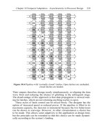
During wafer sort, where bare die is tested, the on-package band-gap
reference is not available and the band-gap reference is replaced by a fixed
voltage. Firmware is loaded into the microcontroller to evaluate the
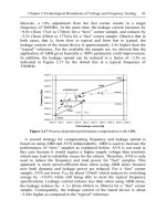
linearity and gain of the voltage/VCO count table. In Figure 12.13, this
process is shown using both a good and a bad part.
Figure 12.13 Process for evaluating VCO table.
For the bad part, an increase in voltage from 1.007 to 1.015 caused a
decrease in VCO count from 21391 to 21389. This behavior would cause
the count 21390 to make to both 1.011V and 1.006V making voltage
measurement far too inaccurate to measure power accurately.
With the testing of the VCO complete, the on-package parasitic
resistance can be measured. If the resistance is too low, not enough
voltage delta will be generated under load to get an accurate power
measurement. If the resistance is too high, significant power is wasted in
the package itself.
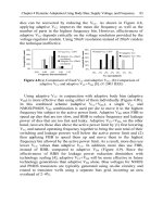
By measuring the voltage drop across the connector (V
c1
–V
d1
) using the
VCO while the chip is idle and consuming standby current I
0
and then
measuring the voltage drop (V
c2
–V
d2
) while the chip is under a known
additional current load, I
Delta
, the package resistance can be computed using
a simple formula (Figure 12.14). This formula, once again, is applied
using special firmware in the microcontroller and the range is tested to be
within acceptable limits (Figure 12.15).
294 Eric Fetzer, Jason Stinson, Brian Cherkauer, Steve Poehlman
Figure 12.14 Graphical representation of Rpkg measurement. (© IEEE 2006)
Figure 12.15 Computation and test of R
pkg
.
12.3.4 Power Measurement Impacts on Other Testing
During operation the package resistance is not a constant. As package
temperature increases so does the resistance of the package. The
temperature of the processor is a function of processor activity and
ambient temperature of the system. As a result, the resistance of the
package must be recomputed every few microseconds to keep the power
measurement accurate. To do this, the processor must be briefly
interrupted so known currents (I
0
and I
0
+I
Delta
) can be passed through the
connector. This interruption stalls any running code, which is a slight
performance impact. Due to the asynchronous nature of the
microcontroller interface, this stall is not deterministic and cannot be
anticipated by the test infrastructure. In a standard ATE, this delay would
R
pkg
V
olt
ag
Current
I
0
I
0
+ I
Delta
V
c1
- V
d1
V
c2
- V
d2
ΔV
ΔI
R
pkg
=
ΔV
ΔI
e
Chapter 12 The Challenges of Testing Adaptive Designs 295
be seen as a malfunction and the test would fail. As a result, power
measurement, and all functionality that relies on it, must be disabled for
the testing of standard content.
The asynchronous nature of the microcontroller interface is not the only
limitation. Even if the design managed a repeatable and deterministic
interface between power measurement and the processor, the system
would still need to be disabled during testing. In order to guarantee robust
functionality over the lifetime of operation, parts are tested well beyond
their normal operation limits. This ensures that as silicon performance
degrades with continued use, the part stays with specification. In testing
beyond the normal limits, the part will exceed its maximum specified
power. This would cause the power management system to measure a
power that is “too high” and place the chip in a reduced performance
mode. Figure 12.16 shows a typical shmoo of a part with a frequency
limiting critical path. This path forces the frequency of the part to be
reduced at low voltage.
0.80
0.90
1.00
1.10
1.20
1.30
1.40
1.00 1.20 1.40 1.60 1.80 2.00 2.20
Over Power
Failing Functionality
Bin Point
Speed
Margin
Frequency (GHz)
Voltage (V)
Over Power
Failing Functionality
Bin Point
Not Measured
Data, illustrative
purposes only
Frequency (GHz)
Voltage (V)
Figure 12.16 Speed-path shmoo with max power line.
296 Eric Fetzer, Jason Stinson, Brian Cherkauer, Steve Poehlman
The bin point (the point at which the part will operate when in use by a
customer) requires a speed margin, or guard-band, be applied from the
failing region. While the bin point is well below the maximum power line,
the bin point combined with the necessary speed margin exceeds the
maximum power. If power measurement were enabled the processor
would observe this excess power during test and limit the instructions
being executed to lower the power. This change in behavior would cause
the test to fail and eliminates the ability to test with the margin required.
12.3.5 Test Limitations and Guard-Banding
In traditional testing, margin (also known as guard-band) is used to ensure
reliable operation when the part is operating in less than ideal conditions.
Guard-bands are required for many reasons including:
• Tester limitations: The accuracy of voltage supplied and thermal
control on the tester is limited.
• Content limitations: System traces for large applications used to
measure power often need to be approximated (reduced in size) when
run on a tester.
• Transistor aging: As silicon is stressed over time, transistor
performance degrades.
Adaptive circuit techniques are often used to enable reductions in these
guard-bands. For example, a part that can measure its own power and can
react to it can adjust its own consumption to stay within the required
envelope. For a non-adaptive design, the worst-case power code must be
tested and a guard-band applied to ensure no future code exceeds the test
power consumption. An adaptive design can have less guard-band because
if future code draws more power from the chip, the part will “do the right
thing.” However, it is not quite this simple. The adaptive part requires
guard-bands for each of its measurement and adjustment systems. In the
case of power measurement, there is error in the package resistance
measurement due to thermal drift. There are also inaccuracies in the
voltage measurement caused by power supply noise and VCO non-
linearities. As a result, implementation details determine whether or not
actual guard-banding is reduced. In the case of power measurement on the
Itanium 2, the sum of guard-bands for power measurement circuitry is less
than 5%, while the potential error in power code is significantly larger,
making adaptation a win.
Chapter 12 The Challenges of Testing Adaptive Designs 297
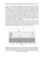
The Itanium 2 has a thermal management system very similar to power
measurement. Using the same VCO (Figure 12.17) as in the power
measurement system, the thermal solution has the resolution to measure
temperature with a precision << 1ºC.
Figure 12.17 Block diagram of thermal measurement. (© IEEE 2006)
However, in order to calibrate the system a known temperature with <<
1ºC of error needs to be supplied by the test environment. The test
environment has to test parts with varying power draw, in a short amount
of time, and with limited thermal probes. To achieve the desired thermal
control in a test environment, the part would need to be submerged in an
oil bath. This is not possible while achieving the required test throughput.
As a result, the accuracy of the thermal monitoring system is not limited
by the processor capabilities, but instead is limited by the capabilities of
the test environment.
As more and more adaptive techniques are used to stretch the capabilities
of silicon, investments will need to be made in validation and test systems
to fully utilize the new capabilities. Adaptive circuit techniques have the
ability to reduce processor guard-bands provided the test infrastructure can
emulate the use conditions adequately.
12.4 Guard-Band Concerns of Adaptive Power
Management
After one considers the correctness of adaptable systems, one must deliver
the value that they offer in the product environment. One of the primary
298 Eric Fetzer, Jason Stinson, Brian Cherkauer, Steve Poehlman
manufacturing considerations in designing an adaptive frequency/power
control system is performance variability tolerance. A system based on
any type of analog measurement will inherently be susceptible to part-to-
part variation as well as environmental variation.
For example, the Montecito system that makes an on-die analog
measurement of the power being consumed will be subject to part-to-part
variation —no two parts will have exactly the same mix of leakage and
dynamic power. This means as voltage is raised or lowered, the power
consumed by parts will vary compared to one another. The same is true
with temperature variation, which affects the leakage power but not the
dynamic power. Also, the ideal voltage versus frequency curve is subject
to part-to-part variation, and attempting to optimize this on a per-part basis
will introduce additional variability.
This variability can also be a function of more subtle effects such as the
aging of components. Voltage regulator outputs may drift as they age,
cooling systems may provide less airflow, and even the leakage of the
processor itself changes with aging. Thus, it is exceedingly difficult to
make a processor that behaves identically from run-to-run and part-to-part
throughout its lifetime if it depends on an analog power measurement for
the basis of its performance adaptability. Systems that depend on a
temperature measurement to adapt performance are subject to similar
variability compared to those that measure power directly.
Reducing the number of possible operating conditions from a continuous
curve to a series of a few discrete conditions greatly reduces the exposure
to variability, as most variation will not be enough to move from one
operating condition to the next. However, if absolutely deterministic
behavior is required of a design, another approach is to replace analog
sensing with architectural event counters.
Using architectural counters [19], specific architectural events can serve
as a proxy for power dissipation, by weighting each one according to its
expected contribution to the power. Assuming the weighting is not done
on a part-by-part basis, all processors will behave identically on identical
code streams. This potentially gives up some benefits of the analog
schemes, which squeeze out more from the design by using actual power
or temperature measurements instead of a proxy. However, this even-based
approach guarantees part-to-part and workload-to-workload
repeatability—also making benchmarking and design debug much more
straightforward.
Chapter 12 The Challenges of Testing Adaptive Designs 299
From a manufacturability standpoint, both analog and architectural designs
require similarly sized guard-bands (Adaptive Op. Point, Figure 12.18) to
guarantee power stays within limits. Because of issues in testing and
operation, this guard-band is larger than the guard-band required at a non-
adaptive operating point. From an analog perspective, the design is
dependent on the ability to make an accurate current measurement, often in
the noisy environment of a running system.
0.80
0.90
1.00
1.10
1.20
1.30
1.40
1.00 1.20 1.40 1.60 1.80 2.00 2.20
Frequency (GHz)
Voltage (V)
Not Measured
Data, illustrative
purposes only
Frequency (GHz)
Voltage (V)
No Adapt
Op. Point
Worst
Case Activity
Code @ P
max
Frequency (GHz)
Voltage (V)
Not Measured
Data, illustrative
purposes only
Frequency (GHz)
Voltage (V)
No Adapt
Op. Point
Worst
Case Activity
Code @ P
max
Real App
Activity Code
@ P
max
Large
Guardband for
Power measurment
variability
Small
Guardband for Test
environment issues
Adaptive
Op. Point
Figure 12.18 Comparison of operating point with and without adaptation.
Architectural counters are not subject to analog noise or accuracy, but
they must be placed and weighted carefully in order to provide the best
mapping to power. One drawback of the architectural approach is that the
worst-case power event needs to be well understood to be detected and the
system needs tuning based on silicon-collected data to be accurate.
Another drawback is that it is very difficult to cover data-dependent
power. That is to say, you can map a certain architectural operation to a
given power level, but you cannot easily modify that power level based on
the operands or the specific data being manipulated, as this requires too
deep a penetration of the architectural monitors.
Determinism and repeatability give architectural power estimates a
significant advantage over the analog measurements. Unlike the situation
where the analog measurement-based power management must be disabled
for almost all production testing, an architectural power-based system will
300 Eric Fetzer, Jason Stinson, Brian Cherkauer, Steve Poehlman
determine steps to maintain a constant power level. While voltage and
frequency responses may not be properly emulated on the tester, the
measurement system itself will behave in a predictable and testable manner.
12.5 Conclusion
From wafer test to final testing of parts in systems, determinism and
repeatability are the cornerstones of bringing a processor design to market.
Adaptive techniques used in modern processors like those demonstrated in
this chapter make determinism and repeatability difficult to achieve. In
some cases, the test infrastructure is not able to keep up with the
processor’s ability to adapt, and as a result the guard-bands that adaptation
is trying to eliminate will remain. Careful planning, along with novel test
techniques like the ones described in this chapter, needs to be employed to
realize the full potential of adaptive techniques. Additional significant
breakthroughs will be required for higher levels of adaptation involving
applications, OS, firmware, system components, and the processor to be
fully production testable.
References
[1] Naffziger, S., et al., “The Implementation of a 2-core Multi-Threaded
Itanium-Family Processor,” IEEE Journal of Solid-State Circuits, Vol. 41,
No. 1 pp. 197–209, Jan. 2006
[2] Thompson, S., et al., “A 90 nm logic technology featuring 50 nm strained
silicon channel transistor, 7 layers of Cu interconnects, low k ILD, and 1 μm
2
SRAM cell,” Electron Devices Meeting, 2002. IEDM '02. Digest.
International, pp. 61–64, Dec. 2002
[3] Mahoney, P., Fetzer, E., et al., “Clock distribution on a dual-core, multi-
threaded Itanium®-family processor,” Solid-State Circuits Conference, 2005.
Digest of Technical Papers. ISSCC. 2005 IEEE International, Vol. 1, pp.
292–599, 6–10 Feb. 2005
[4] Anderson, F.E., Wells, J.S., Berta, E.Z., “The core clock system on the next
generation Itanium microprocessor,” Solid-State Circuits Conference, 2002.
Digest of Technical Papers. ISSCC. 2002 IEEE International, Vol. 1, pp.
146–453, 3–7 Feb. 2002
[5] Geannopoulos, G., Dai, X., “An adaptive digital deskewing circuit for clock
distribution networks”, Solid-State Circuits Conference, 1998. Digest of
Technical Papers. 45th ISSCC 1998 IEEE International, pp. 400–401, 5–7
Feb. 1998
Chapter 12 The Challenges of Testing Adaptive Designs 301
[6] Peterson, W.W., Weldon, E.J., Jr., Error-Correcting Codes, 2nd editions,
MIT Press: Cambridge Mass., 1972
[7] Ziegler, J. F., Srinivasan, G. R., et al, “Terrestrial cosmic rays and soft
errors,” IBM Journal of R and D, Vol. 40 No.1 1996
[8] Ershov, M., Saxena, S., et al., “Dynamic recovery of negative bias
temperature instability in p-type metal-oxide-semiconductor field-effect
transistors,” Applied Physics Letters, , Vol. 83, No. 8, pp. 1647–1649,
August 25 2003
[9] Agostinelli, M., et al., “Erratic fluctuations of SRAM cache Vmin at the
90nm process technology node,” Electron Devices Meeting, 2005. IEDM
Technical Digest. IEEE International, pp. 655–658, Dec. 5 2005
[10] McGowen, R., Poirier, C., et al., “Power and Temperature Control on a 90-
nm Itanium Microprocessor,” Solid-State Circuits, IEEE Journal of Vol. 41,
No. 1, pp. 229–237, Jan. 2006
[11] Wayne Needham, Cheryl Prunty, Eng Hong Yeoh, “High Volume
Microprocessor Test Escapes, An Analysis Of Defects Our Test Are
Missing”, IEEE International Test Conference, pp. 25–34, 1998.
[12] Mike Mayberry, John Johnson, Navid Shahriari, Mike Trip, “Realizing the
Benefits of Structural Test For Intel Microprocessors”, IEEE International
Test Conference, pp. 456–463, 2002.
[13] Ismet Bayraktaroglu, Jim Hunt, Daniel Watkins, “Cache Resident Functional
Microprocessor Testing: Avoiding High Speed IO Issues”, IEEE
International Test Conference Conference, 2006.
[14] Huston, R., “Microprocessor Functional Test Generation on the Sentry 600”,
IEEE International Test Conference, 1974.
[15] Praveen Parvathala, Kailas Maneparambil, William Lindsay, “ FRITS – A
Microprocessor Functional BIST Method”, IEEE International Test
Conference, pp. 590–598, 2002.
[16] Krantis, N., Xenoulis, G., Paschalis, A., Gizopoulos, D., Zorian, Y.,
“Application and Analysis of RT-Level Software-Based Self-testing for
Embedded Processor Cores”, IEEE Intetrnational Test C440.
[17] Wei-Cheng Lai, Kwang-Ting Cheng, “Instruction-Level DFT for Testing
Processor and IP Cores in System-on-a-Chip”, Design Automation
Conference ,pp. 59–64, 2001.
[18] Tsang, J., et. al., “Picosecond imaging circuit analysis”, IBM Journal of
Research and Development, Vol. 44, No. 4, pp. 583–603, 2000.
[19] Leon, A. S., et al., “A Power-Efficient High-Throughput 32-Thread SPARC
Processor,” IEEE J. Solid-State Circuits, Vol. 42, No. 1, pp. 7–16, Jan. 2007.
[20] Harry Hsiung, “Manufacturing and test Solutions with EFI”, Intel
Developers Forum, 2003.
[21] Peter Maxwell, Ismed Hartanto, Lee Bentz, “Comparing Functional and
Structural Tests”, IEEE International Test Conference, pp. 400–407, 2000.
[22] Satish M. Thatte, Jacob A. Abraham, “Test Generation For Microprocessors”,
IEEE Transactions On Computers, Vol. 29, No. 6, pp. 429–441.
[23] Advanced Configuration and Power Interface Specification, rev 3.0b,
o/spec.htm, October 2006
Index
Adaptive body-bias, 25, 45, 77
Adaptive voltage scaling, 25
Aging, 87, 151
negative bias temperature
instability (NBTI), 11
Asynchronous design, 230
bundled data, 230
dual-rail, 231
Asynchronous latch controller, 240
Body-bias, 2, 12, 20
adaptive, 4, 25, 45, 77
controller, 88
forward, 27, 60
reverse, 27, 55
Canary circuits, 179
Clock generation, 138
Clocking
jitter, 150
skew, 150, 274
Control loop, 199
Critical path, 145, 210
DC-DC, 108
inductor-based, 109
switched-cap, 110
Device sizing, 98
Drain induced barrier lowering
(DIBL), 17, 50
Dynamic voltage scaling (DVS), 26,
50, 95, 123, 126, 176
Error correction coding, 106, 277
Error detection, 182
Frequency island, 207–208
Frequency optimization, 33
Globally asynchronous, locally
synchronous (GALS), 208
Guardbands, 299
Hardware and software control, 68
In-situ monitor, 181
Leakage current
gate, 2, 17, 50
gate edge diode leakage (GEDL), 18
gate induced diode leakage
(GIDL), 20, 39
subthreshold, 2, 17, 50
Leakage current monitor, 56
Low-dropout (LDO), 109
Manufacturing test, 272, 279
ATPG, 280
clock de-skew, 288
power management, 289
wafer sort, 280
Microprocessor, 121
Minimum energy tracking, 112
Negative bias temperature instability
(NBTI), 11
Noise, 145
Operating system control (OS), 70
Performance monitor, 128
PLL, 87, 138
Power monitor, 279
Power optimization, 33
Process variation, 41, 79, 145, 149,
175, 207, 210, 267
die-to-die, 79
304 Index
Random dopant fluctuations, 11
Ring oscillatior, 33
Shadow latch, 187
Short-channel effect, 59
SRAM, 101, 134, 249
active sleep, 260
bias generator, 262
passive sleep, 261
read assist, 257
reliability, 267
replica path, 258
soft errors, 267
subthreshold, 107
timing, 257
write assist, 253
Static noise margin (SNM), 134
flip-flops, 97
read, 104, 250
SRAM, 104
write, 250
Sub-threshold CMOS, 97
Supply voltage variation, 150, 177
Technology scaling, 1, 26, 75, 175
Temperature variation, 7, 57, 150,
177, 207, 217
Threshold-voltage variation, 13
Ultra dynamic voltage scaling, 95
Variable channel-length, 5
Variable frequency scaling, 207
Variable threshold CMOS
(VTCMOS), 55
Voltage/frequency hopping, 51
Voltage controlled oscillator
(VCO), 280
Voltage regulator, 278
Voltage scaling, 2
adaptive, 25
Continued from page ii
Abstraction Refinement for Large Scale Model Checking
Chao Wang, Gary D. Hachtel, and Fabio Somenzi
ISBN 978-0-387-28594-2, 2006
A Practical Introduction to PSL
Cindy Eisner and Dana Fisman
ISBN 978-0-387-35313-5, 2006
Thermal and Power Management of Integrated Systems
Arman Vassighi and Manoj Sachdev
ISBN 978-0-387-25762-4, 2006
Leakage in Nanometer CMOS Technologies
Siva G. Narendra and Anantha Chandrakasan
ISBN 978-0-387-25737-2, 2005
Statistical Analysis and Optimization for VLSI: Timing and Power
Ashish Srivastava, Dennis Sylvester, and David Blaauw
ISBN 978-0-387-26049-9, 2005