ARNOLD, K. (1999). Design of Gas-Handling Systems and Facilities (2nd ed.) Episode 2 Part 9 ppt
Bạn đang xem bản rút gọn của tài liệu. Xem và tải ngay bản đầy đủ của tài liệu tại đây (1.27 MB, 25 trang )
436
Design
of
GAS-HANDLING
Systems
and
Facilities
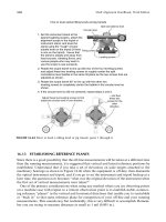
Figure
15-7.
Diaphragm
valve.
(Courtesy
of
Flexible
Valve
Corp.)
Check
Valves
Used
to
restrict reversal
of
flow,
check valves should
not be
consid-
ered
as
positive
shut-off
valves when
flow is
reversed, since
the
seating
element
is
always
in the flow
stream
and
subject
to
erosion
(Figures
15-9
to
15-13).
A
section
of a
line should
not be
considered
isolated
if the
only
barrier
to
flow
is a
check
valve.
On the
other hand,
because
they
do
restrict
backflow
to
very
low
levels, check valves installed
in
appropriate
locations
can
protect equipment
and
minimize damage
in
case
of a
leak
in
the
upstream line. Some
of the
advantages
and
disadvantages
of the
various
check
valve configurations
are as
follows:
•
Swing
1.
Suitable
for
non-pulsating
flow.
2. Not
good
for
vertical upward
flow.
3.
Available
in
wafer design
for
mounting between
flanges.
•
Split Disk
1.
Mounted between
flanges.
2.
Springs subject
to
failure.
•
Lift
Plug
and
Piston
1.
Good
for
pulsating
flow.
2.
Can be
used
in
vertical upward
flow.
3,
Easier
to cut out in
sandy service than full-opening swing.
4,
Subject
to
fouling
with
paraffin
and
debris.
Valves, Fittings,
and
Piping
Details
437
Figure
15-8.
Needle valve.
(Courtesy
of
Anderson
Greenwood
and
Co.)
438
Design
of
GAS-HANDLING
Systems
and
Facilities
Figure
15-9.
Swing
check
valve.
(Courtesy
ofJudd
Valve
Co.,
inc.}
•
Ball
1.
Does
not
have
a
tendency
to
slam shut
on flow
reversal.
2.
Usually
for
sizes
1-in.
and
smaller.
3. Can be
used
in
vertical lines.
Valve
Selection
and
Designation
Table
15-3 summarizes
and
compares
the
different
valve types dis-
cussed
in
this chapter
and
highlights important
properties
that impact
valve
selection.
It is
beneficial
to
designate valve types
in
schematic drawings
of the
facilities.
The
designation should indicate
the
type
of
valve (ball, gate,
etc.)
the
type
of end
connection
(flange,
socketweld,
threaded, etc.),
the
pressure rating class (ANSI 150, ANSI 600,
API
2000,
etc.)
and the
materials of
construction. Table
15-4
shows
a
sample designation system.
Using this system,
the
designation
VBF-15-1
would
indicate
an
ANSI
150
flanged ball valve.
The
specific attributes would then come
from
a
pipe, valve,
and
fitting
specification, such
as
Table 15-2,
or
from
a
sepa-
rate
valve
specification
for
VBF-15-1,
as
shown
in
Table 15-5.
Table
15-3
Comparison
of
Valve
Properties
Valve
Ball
Plug
Gate
Butterfly
Globe
Needle
Check
Choke
Bubble
Tight
Yes
Yes
Yes
Yes
for
low AP
ANSI
150
Not
All
Yes
No
Yes
Adjustable
choke only
Throttle
No
On/Off
No
On/Off
Some
Yes
Gas Low AP
Yes
Yes
No
Yes
Adjustable
choke only
Where
Used
Isolation
ubiquitous
Isolation
Rare
Control,
wellhead isolation,
double block
&
bleed
Isolation/Control
Control
bypass, vent
Inst/Control
To
restrict
reversal
of
flow
Isolation
Control
Pig
Yes
(Full)
No
Yes
No
No
No
Roddable
Swing
check
Valves only
some cases
No
Pressure
Drop
Low
Low
Low
Low
High
Low
High
Size
r-36"
Rare
Cheaper than ball
2"-Up
Larger sizes
cheaper than ball
2"-Up
Larger sizes cheaper
than
globe
2"-Up
1
A"-\W
l
A
/f
-36"
2"-9"
Bigger diameters
special order
Courtesy
of
Paragon
Engineering Services, Inc.
440
Design
of
GAS-HANDLING
Systems
and
Facilities
Table
15-4
Sample
Valve
Designation
System
Each valve designation
has
four
(4),
and
possibly
five
(5), parts.
(1)
This
part
of
each valve designation
is
always
V,
which stands
for
"valve,"
(2)
The
second letter identifies valve
type:
B
=
Ball
C
=
Check
D
=
Diaphragm
G
=
Gate
N
=
Needle
O =
Globe
P
=
Plug
Y
=
Butterfly
(3)
The
third letter identifies
end
connections:
T
=
Threaded
S
=
Socketweld
F =
Flanged
B
=
Buttweld
(4)
The
fourth
part
of
each valve designation
is a
2-,
3-,
or 4-
digit number
indicating
the
highest ANSI
or API
class
for
which
the
valve
can be
used:
15
=
ANSI
150
30 =
ANSI
300
60 =
ANSI
600
90 =
ANSI
900
150
=
ANSI 1500
250
=
ANSI
2500
200 =
2000*
API
300 =
3000#
API
500 =
5000#
API
(5)
The
fifth
part
of a
valve designation, when used,
is a
modifier that
distinguishes between
two or
more valves that have
the
same type
and
pressure rating
but
that
are
considered separately
for
some other reason.
Courtesy
of
Paragon Engineering Services, Inc.
CHOKES
Chokes
are
used
to
control
flow
where
there
is a
large
pressure
drop.
They
can
either
be
adjustable,
where
the
opening
size
can be
varied
man-
ually
as
shown
Figure
15-14
and
15-15
or
have
a
fixed
size
orifice.
Due
to the
erosive
nature
of the
fluid flow
through
a
choke,
they
are
con-
structed
so
beans,
discs,
and
seats
can be
easily
replaced.
Valves,
Fittings,
and
Piping Details
441
Table
15-5
Sample
Valve
Table
Valve
Designation:
VBF-15-1
Service:
Hydrocarbons, Non-corrosive
Glycol
Type:
Ball Valve
Rating:
ANSI
150
Design Temperature Design Pressure
-20°
to
100°F
285psig
to
200°F
260
psig
to
300°F
230
psig
Pressure Rating: ANSI
150
Body
Material: Carbon Steel
Trim Material: Hard Plated Carbon
Steel
Ball
End
Connection:
RF
Flanged
Valve
Operator: Lever through
8",
Gear Operated
10"
and
larger
Body
Construction:
2"-4":
Floating Ball, Regular Port
6" and
larger:
Trunnion Mounted
Ball,
Regular Port
Trim
Construction: Renewable Seats, Removable Stem, Fire
Safe
Valve
Comparison
List
Manufacturer
Manufacturer's
Fig.
No.
Nominal
Sizes
WKM
310-B100-CS-02-CS-HL
W-4"
WKM
370CR-ANSI150RF21-AAF-21
6'-14"
^Demco
121136X
?H?1_
PIPING
DESIGN
CONSIDERATIONS
Process
Pressures
Maximum
allowable
working pressure
(MAWP):
Highest pressure
to
which
the
system
can
be
subjected during
operation.
Thus, pressure
is
established
by a
relief device
set
pressure
and
must
be
less than
or
equal
to
the
material strength limitations
of
equipment. This pressure establish-
es
piping class
for fittings and
pipe
wall
thickness requirements, both
of
which
are
discussed
in
Volume
1.
Normal
operating pressure: Anticipated process operating pressure
used
to
determine pipe diameter requirements
and
pressure drop limita-
tions
for
various operating conditions.
442
Design
of
GAS-HANDLING
Systems
and
Facilities
Figure
15-10.
Wafer
check
valve.
(Courtesy
of
TRW
Mission
Drilling
Products
Division.}
Figure
15-11.
Lift
check
valve.
(Courtesy
of
Jenkins
Bros.}
Valves,
Fittings,
and
Piping Details
443
Figure
T5-12.
Piston
check
valve.
(Courtesy
of
Whealtey
Pump
and
Valves,
Inc.]
Figure
15-13.
Ball check
valve.
(Courtesy
of
Wheatiey
Pump
and
Valves,
Inc.]
444
Design
of
GAS-HANDLING
Systems
and
Facilities
Figure
15-14.
Plug
and
seat
choke.
(Courtesy
of
Willis
Control
Division,
Cameron
Iron Works, Houston.)
Figure
15-15.
Rotating
disc
choke.
[Courtesy
of
Willis Control Division, Cameron
Iron Works, Houston.)
Valves,
Fittings,
and
Piping
Details
445
(text
continued from
page
441)
Future
operation pressures: Sizing
of
lines must consider operating
pressures expected
as the
reservoir depletes. Diameter requirement calcu-
lations
should
be
made using both initial
and
future
conditions
to
deter-
mine
the
governing
case. Often
in gas and
two-phase lines
the
greatest
flow
velocity
occurs late
in
life
when
flowing
pressures
are low
even
though
flow
rates
may be
lower
than
initial
conditions.
Process
Temperatures
Design
temperature: Highest
or
lowest (depending upon which
is
con-
trolling) temperature
to
which
a
line
can be
subjected during operation.
Normal
operating temperature:
Anticipated
process operating temper-
ature
used
to
determine pipe diameter
for
various operating conditions.
Process
Liquid
Flow
Rates
Liquid
lines
in
production facilities
are
generally
in
either continuous
or
slugging service. Continuous duty lines should
be
sized
to
handle
the
average daily
flow
rate
of the
facility.
An
additional capacity
is
often
added
for
surges. Lines
in
slugging service should
be
sized
to
accommo-
date actual
flowing
conditions. Design
flow
rates should
be the
maxi-
mum
capacity that
a
line will accommodate within
the
design limits
of
velocity
and
pressure drop, both initially
and in the
future.
Process
Gas
Flow
Rates
The
sizing procedure
for gas
piping must take both high-pressure
and
low-pressure
flow
conditions into consideration
if the
operating pressure
of
the
line changes over time.
Two-Phase
Flow
Rates
Whenever
two-phase
flow is
encountered
in
facility
piping
it is
usually
in
flowlines
and
interfield
transfer lines. Some designers size liquid lines
downstream
of
control valves
as
two-phase lines.
The
amount
of gas
involved
in
these lines
is low and
thus
the
lines
are
often
sized
as
single-
phase liquid lines. Oversizing two-phase lines
can
lead
to
increased slug-
ging
and
thus
as
small
a
diameter
as
possible
should
be
used;
consistent
with
pressure drop available
and
velocity constraints discussed
in
Volume
1.
446
Design
of
GAS-HANDLING
Systems
and
Facilities
Viscosity:
High viscosity crudes
may
flow
in the
laminar
flow
regime
which
causes high pressure drops. This
is
especially
true
of
emulsions
of
water
in
high-viscosity crudes where
the
effective
velocity
of the
mixture
could
be as
much
as ten
times that
of the
base
crude
(see
Volume
1).
Solids:
Some wells produce large amounts
of
sand
and
other solids
entrained
in the fluid.
Where
solids
are
contained
in the
stream,
sufficient
velocity
should
be
provided
to
assure they
do not
build
up in the
bottom
of
the
pipe, causing higher than anticipated pressure drops
or
potential
areas
for
corrosion. However,
if the
velocity
is too
high,
erosion
may
occur,
(See
Volume
1.)
Fluid
Compositions
The
composition
of a
production
fluid is
usually
not
well
defined.
In
most
cases,
only
a
specific gravity
is
known. Compositions
are
important
to
the
prediction
of
physical
properties
of the fluid as it
undergoes phase
changes.
Estimations
can be
made based only upon specific gravity,
how-
ever,
for
good reliability, molecular compositions should
be
used
when
available.
Gases such
as
H
2
S
and
CO
2
(acid
gases)
in the
production
streams
are
sometimes encountered.
These
gases
are not
only corrosive
to
piping,
but
many
are
harmful
and
possibly fatal upon
contact
with humans.
Special
care should
be
exercised
in
designing piping containing acid gases.
Velocities
above
30 to 50
ft/s
should
be
avoided
in
piping containing acid
gases
to
avoid
affecting
the
ability
of
corrosion inhibitors
to
protect
the
metal.
Special metallurgy
may be
needed
to
combat
H
2
S
corrosion.
(See
Chapter
8.)
Handling Changing Operating
Conditions
Each
production
facility
has
three
categories
of
equipment whose
design
depends upon operating conditions:
1.
Vessels
and
other mechanical equipment
are the
most
difficult
to
change
or
alter
after
installation.
2.
Piping
is the
next most
difficult.
3.
Instrumentation
is
the
least
difficult.
Often
the
facility
is
designed with equipment
and
piping that
can
han-
dle
the
complete
range
of
operating
conditions,
and
with control valves
selected
so
that their internals ("trim")
can be
substituted
as
operating
Valves,
Fittings,
and
Piping Details
447
conditions
change. Sometimes
the
piping must
be
designed
to
allow
addition
of
future
pieces
of
equipment. This
is
especially true
for
com-
pressors
and
water treating equipment that
may not be
needed initially.
The key to
arriving
at the
most
flexible
system design lies
in forecast-
ing
future
operating conditions. Many engineers
are not
aware
of the
implications
of
future
conditions
and
their
effect
upon initial design
arid
long-term
operation.
Often
some information
is
available
on
potential
future
scenarios,
but the
facility
design engineer
elects
to
design
for a
specific
'"most
likely"
forecast. This
is
unfortunate,
as the
designer
should
at
least consider
the
sensitivity
of
the
design
and
economic
conse-
quences
to the
whole range
of
possible
forecasts.
Selecting
Pipe
Sizes
Basic
steps
in
piping design
are:
1.
Establish operating conditions,
i.e.,
flow
rates, temperatures, pres-
sures
and
compositions
of fluid
over
the
life
of the
system. This
may
involve
several cases.
2.
Using velocity
as the
limiting criterion, calculate allowable pipe
internal
diameter ranges using
the
criteria
of
Chapter
9,
Volume
1.
3. If
more than
one
standard pipe size
is
indicated, calculate
the
wall
thickness
for
each standard pipe size based
on
required maximum
allowable working pressure
and
select
a
standard wall thickness
for
each
size.
4.
Calculate maximum
and
minimum capacities
for
each size using
velocity
limits
as
criteria.
5.
Estimate
the
pressure drop
for
each size
and
compare
to the
avail-
able
pressure drop.
6.
Arrange
the
information
from
the
previous steps
and
determine
which
pipe size
is
best suited
to all
operating conditions.
7.
As
piping drawings
are
developed, re-evaluate
those
lines
where
estimated pressure drop
was a
criterion
in
size selection, taking into
account
the
actual piping configuration
and
effects
of
control
and
piping
components.
8.
Proceed
with
design
of
pipe supports
and
stress analysis,
if
required.
It
is
also
a
good practice
to
verify
design conditions
and
piping calcu-
lations
just prior
to
release
of the
drawings
for
construction. System
requirements
sometimes change significantly during
the
course
of a
pro-
448
Design
of
GAS-HANDLING
Systems
and
Facilities
ject.
In
most facility piping situations experienced
designers
can
select
size
quickly
without
a
formal tabulation
of the
steps just described.
In
certain
cases,
especially where pressure drop
is an
important
considera-
tion,
a
formal tabulation
may be
required,
GENERAL
PIPING
DESIGN
DETAILS
Steel
Pipe
Materials
Most
production
facility
piping
is
fabricated
from
ASTM
A-106
Grade
B
or
API 5L
Grade
B
pipe, which
is
acceptable
for
sweet service
and
tempera-
tures
above
~20°F.
Between
-20 °F and -50 °F,
ANSI
B31.3,
"Chemical
Plant
and
Petroleum Refinery Piping," allows this material
to be
used
if the
pressure
is
less than
25% of
maximum allowable design
and the
combined
longitudinal
stress
due to
pressure, dead weight,
and
displacement strain
is
less
than
6,000
psi. Below
-50°F
it is
required that
the
pipe
be
heat treated
and
Charpy
impact tested. Volume
I,
Chapter
9
discusses
the
various com-
mon
piping codes
and
methods
for
calculating maximum allowable pres-
sure
for
various steels. Some common low-temperature steels include:
Steel
Minimum
Temp,
without
Special
Testing
A-333
Grade
!
-
SOT
A-334
Grade
1 -
50°F
A-312TP304L
-425°F
A^12_TP316L
If^I
For
sour service,
National
Association
of
Corrosion Engineers
(NACE)
MR-01-75
requires that steel material have
a
Rockwell
C
hard-
ness
of
less than
22 and
contain less than
1%
nickel
to
prevent
sulfide
stress
cracking.
Figure
7-1
shows
regions
of
H
2
S
concentration
and
total
pressure
where
the
provisions
of
NACE
MR-01-75
govern. A-53 Grade
B,
A-106
Grade
B,
A-333 Grade
1, and API 5L
Grades
B and
X-42 through
X-65
are
acceptable
for use in the
sulfide-stress cracking region.
Minimum
Pipe
Wall
Thickness
From
the
standpoint
of
mechanical strength, impact resistance,
and
cor-
rosion
resistance,
some operators prefer
to
establish
a
minimum wall thick-
ness
of
approximately 0.20
in.
Thus, they establish
the
following
minimum
Valves,
Fittings,
and
Piping
Details
449
pipe
schedules (standard wall thickness), even though pressure
contain-
ment
calculations would indicate
that
smaller thicknesses
are
allowed:
%
in. and
smaller
— Sch 160
2,
2!i
and 3 in. — Sch 80
4 and 6 in. — Sch 40
ANSI
B
31.3
requires threaded pipe that
is
VA
in. and
smaller
be at
least
Sch
80 and
that
2 in.
and
larger
be at
least
Sch 40.
Pipe
End
Connections
Pipe, valve,
and
fittings
tables must specify which size
of
each class
of
pipe
is
threaded, flanged,
or
socket welded. ANSI
B31.3
provides
no
spe-
cific
guidance except that
it
suggests that threads
be
avoided where
cor-
rosion, severe
erosion,
or
cyclic loading
is
anticipated.
API
RP
14E
recommends:
•
Pipe
1
[
A.
in. or
less should
be
socket welded for:
Hydrocarbon
service above
600
ANSI
Hydrocarbon
service above 200°F
Hydrocarbon
service subject
to
vibration
Glycol
service
•
Pipe
2
inches
and
larger should
be
flanged
for:
Hydrocarbon
service
Glycol
service
«
Utility
piping
2
inches
and
smaller
may be
threaded.
A
common practice onshore
is to use
threaded connections
on
2-in.
pipe
or
smaller,
no
matter what
the
service.
It is
also
common
to see
threaded connections
on
4-in.
pipe
and
smaller
in low
pressure
oil
service.
Figure
15-16
shows three types
of flange
faces. Raised-face
(RF)
and
flat-faced
(FF)
flanges use a
donut-shaped
flat
gasket
to
create
the
pres-
sure
seal. Ring-joint
flanges
(RTJ)
use a
ring that
fits
into
the
circular
notches
in the
face
of the flange to
effect
the
pressure seal.
RTJ flanges
create
a
more positive seal
and are
used
for all API
class
flanges and for
higher
pressure ANSI classes. However, they
are
difficult
to
maintain,
as
they
require
the
mating
flanges to be
spread
to
remove
the
ring. Raised-
face
flanges
tend
to
form
a
tighter seal than
flat-faced flanges and are
used
in
steel piping. Flat-face
flanges are
used
in
cast-iron piping
and in
bolting
to
cast-iron
and
ductile-iron pumps, compressors, strainers,
etc.
450
Design
of
GAS-HANDLING
Systems
and
Facilities
Figure
15-16.
Typical
flanges.
Bolting
a
raised-face flange
to a flat-faced,
cast-iron
flange can
create
bending moments
in the
less ductile cast-iron
flange,
which could cause
it
to
crack.
The
ANSI specifications allow
the use of
both
RF and RTJ flanges.
API RP 14E
recommends
RTJ flanges for
ANSI
Class
900 and
higher
and
recommends
RTJ flanges be
used
in 600
ANSI service subject
to
vibration. Onshore
it is
common
to use RF flanges for
ANSI
classes
through
2500.
The
hesitancy
to use RF flanges at
higher pressures
may
stem
from
an
era
when plain
He-in,
asbestos gaskets were
the
only type available.
Mod-
ern
spiral-wound
polytetrafluoroethylene
(PTFE)
filled
with internal
ring
gaskets with
316
stainless-steel windings
may
create
as
positive
a
seal
with
RF flanges as is
obtainable
from
RTJ flanges.
RTJ
gaskets
are
normally cadmium-plated, soft
iron
or low
carbon
steel
Soft
iron
is
used
for
ANSI
600 and 900
classes,
and 304 or 316
stainless steel
for
higher classes.
Branch
Connections
Where
a
branch
connection
is
connected
to a
main
run of
pipe,
it is
necessary
to
specify
the
type
of
fitting
required. ANSI
B31.3
provides
a
Valves,
Fittings,
and
Piping Details
451
procedure
for
calculating
the
amount
of
reinforcement
needed
to
ade-
quately
support
the
branch connection.
In
accordance
with
this
code,
no
reinforcement
is
needed where;
»A
tee is
used.
•
A
coupling
is
used,
the
branch size
is 2 in. or
less,
and the
branch
size
is
less than
14
diameter
of the ran.
• An
integrally reinforced branch connection
fitting
that
has
been
pres-
sure
tested
(weld-o-let
type)
is
used.
API
RP
14E
recommends that
no
reinforcement
be
used
and
presents
a
typical
branch connection schedule (Table
15-6)
to
provide
more
mechanical
strength than
is
required
by
ANSI
B31.3.
Most onshore oper-
ators
use
integrally
reinforced
branch-connection
fittings
or
tees
inter-
changeably.
Fiberglass
Reinforced
Pipe
The use of
fiberglass reinforced pipe (FRP)
and
tanks
has
been
on the
increase
in
production facilities. Onshore applications include low-pres-
sure
flowlines,
high-pressure water injection lines,
oil
treating systems,
fire
water systems,
and
produced water treating systems. Offshore appli-
cations include fire water
and
utility systems.
The
primary advantages
are
ease
of
field
installation
and
non-corrosiveness.
The
American
Petro-
leum
Institute
has
developed specifications
for
fiberglass tanks (API
Spec
12P)
and
fiberglass piping (API Spec
15LR).
insulation
Insulation
is
normally required
for
personnel protection
for
pipe oper-
ating
at
higher than approximately
150°F
or
200°F.
Pipe
operating
at
greater than approximately
400°F
should
be
located
and
insulated
to
keep
it
from
becoming
an
ignition source
for
spilled liquid hydrocarbons.
Pipe
operating
at
temperatures above approximately
900°F
should
be
protect-
ed
from
coming into contact
with
combustible
gases.
As
described
in
Chapter
17, any
surface
in
excess
of
726°F
in an
elec-
trically classified area should
be
insulated
or
isolated from
gas
sources.
A
normal
rale of
thumb
and a
requirement
of
some codes
is to
provide insu-
lation
or
isolation barriers
for
surfaces hotter
than
400°F
that
are
located
within
electrically classified
areas.
Surfaces
in
electrically unclassified
areas
are
only
insulated
or
isolated
if
necessary
for
personnel
protection.
Table
15-6
Branch
Connection
Schedule—Welded
Piping
I 2 3 4 5 6 7 8 9 10 11 12
13
14
15 16
Nominal
Branch
Size
(in.)
Nominal
Run
Size
(in.)
14
%
1
114
2 214 3 4 6 8 10 12 14 16 18
1
A
SWT SWT
SWT
SWT 6SC 6SC 6SC 6SC 6SC 6SC 6SC 6SC 6SC 6SC 6SC
K
SWT SWT SWT SOL 6SC 6SC 6SC 6SC 6SC 6SC 6SC 6SC 6SC 6SC
1
SWT SWT SOL SOL SOL 6SC 6SC 6SC 6SC 6SC 6SC 6SC 6SC
Iti
SWT TR SOL SOL SOL 6SC 6SC 6SC 6SC 6SC 6SC 6SC
2
T RT RT RT WOL WOL WOL WOL WOL WOL WOL
2
1
A
T RT RT WOL WOL WOL WOL WOL WOL WOL
3 T RT RT WOL WOL WOL WOL WOL WOL
4 T RT RT WOL WOL WOL WOL WOL
6 T RT RT RT WOL WOL WOL
8 T RT RT RT RT WOL
10
T RT RT RT RT
12
T RT RT RT
14
T RT RT
16
T RT
18
I
_
T
T—Straight
Tee
(Butt
Weld)
RT—Reducing
Tee
(Butt
Weld)
TR
—Straight
Tee and
Reducer
or
Reducing
Tee
WOL—Welded
nozzle
or
equivalent
{Schedule
of
Branch
Pipe)
SOL—Socketweld
couplings
or
equivalent—6000
Ib
Forged
Steel
SWT—Socketweld
Tee
f)$C—6000
Ih
Forged
Steel
Sockefndd
Coupling
i
'/•
inch
and
smaller
threadbolts
or
screwed couplings
may he
used
for
sample, gage,
test
connection
and
instrumentation purposes
>
Valves, Fittings,
and
Piping
Details
453
Pipe
Insulation Considerations
M^erials
*
Some commonly used insulating materials
are
calcium
silicate, min-
eral
slagwool, glass
fiber,
cellular glass,
and
polyurethane.
*
Insulating material, such
as
magnesia, that
if wet
could deteriorate
or
cause corrosion
of the
insulated surface, should
not be
used.
»Certain
heating fluids
are not
compatible with some insulating mate-
rials,
and
auto-ignition
may
occur. Caution should
be
exercised
in
selecting
materials.
"^^^Barriers
«A
vapor barrier should
be
applied
to the
outer surface
of the
insula-
tion
on
cold piping.
•
Insulation should
be
protected
by
sheet-metal jacketing
from
weath-
er,
oil
spillage, mechanical wear,
or
other damage.
• If
aluminum sheet metal
is
used
for
this purpose, insulation should
be
protected
by a
vapor barrier.
Spjur_Service
»To
prevent
H
2
S
from
concentrating around
the
bolts, flanges should
not
be
insulated
in
H
2
S
service.
Table
15-7 shows recommended insulation thicknesses
from
API
RP14E.
Two
of the
most common types
of
acceptable insulation systems
are:
1.
Metal
jacket—This
type
is
primarily used
on
piping, heat exchang-
ers,
and
other cylindrical shapes.
2.
Blanket—This
type
is
primarily used
on
irregular objects that
are
difficult
to
insulate
due to
irregular surface
configurations—such
as
an
expansion joint.
Examples
of
insulation
and
isolation installations
are
shown
in
Figures
15-17
through 15-24.
(text
continued
on
page
46
J)
Table
15-7A
Typical
Hot
Insulation
Thickness
(in.)
1
2
Maximum
Temperature
rn
250
500
600
750
3
4
5
6
7
8
9
Nominal Pipe
Size,
inches
iv&&
Smaller
1
1
VA
2
2
1
VA
VA
2
3
1
VA
2
2
4
VA
VA
2
2
6
VA
2
2
2
1
A
8
VA
2
2
1
A
3
10
VA
2
2
1
A
3
12&
Larger
VA
2
2
1
A
3
Table
15-7B
Typical Cold Insulation Thickness
(in.)
1
2
Aninttniim
fYlIf
IIIIIwlII
Temperature
ro
40
30
20
10
0
-10
-20
3
4
5
6
7
8
9
10
11
12
13
14
15
16
17
18
19 20
Nominal
Pipe
Size,
in.
H
1
1
VA
VA
VA
2
2
3
/4
1
1
VA
VA
2
2
2
1
1
1
VA
VA
2
2
2
VA
1
VA
VA
VA
2
2
2
]
A
2
1
VA
VA
2
2
2
2
}
A
TA
I
VA
VA
2
2
2
1
A
2
1
A
3
1
VA
VA
2
2
2
1
A
2
1
A
4
1
VA
VA
2
2
}
A
2
1
A
2
1
A
6
1
VA
2
2
2
1
A
2
1
A
3
8
VA
VA
2
2
2
1
A
3
3
10
VA
VA
2
2
1
A
2
1
A
3
3
12
VA
VA
2
2
1
A
2
1
A
3
3
14
VA
VA
2
2
1
A
2
{
A
3
3
16
VA
VA
2
2}A
2
1
A
3
3M
18
VA
VA
2
2
1
A
2
{
A
3
3
1
A
Fiat
20 24 30
Surf,
VA VA VA VA
VA
VA VA VA
2222
2
1
A
1}A
2}A
2
1
A
2
1
A
333
3 3 3
314
3yi
3^
3
{
A
4
Table
15-7C
Typical
insulation
For
Personnel
Protection
(Applicable
Hot
Surface
Temperature
Range
(°F)}
1
2
Nominal
Pipe
Size
(in.)
1
A
%
I
VA
2
2
1
A
3
4
6
8
10
12
14
16
18
20
24
30
3
4
5
Nominal
insulation Thickness
1
160-730
160-640
160-710
160-660
160-640
160-620
160-600
160-600
160-550
_
-
_
-
-
_
-
_
_
Flat
Surface*
j
160-520
114
731-1040
641-940
711-960
661-880
641-870
621-960
601-810
601-790
551-740
160-740
160-750
160-740
160-700
160-690
160-690
160-690
160-680
160-680
521-660
2
1041-1200
941-1200
961-1200
881-1200
871-1090
961-1160
811-1000
791-970
741-930
741-900
751-900
741-900
701-850
691-840
691-830
691-830
681-820
681-810
661-790
2H
_
—
_
_
1091-1200
1161-1200
1001-1200
971-1125
931-1090
901-1090
901-1060
901-1030
851-1000
841-980
831-970
831-970
821-960
811-950
791-900
6
(in.)
3
—
_
_
_
—
_
1126-1200
1091-1200
1091-1200
1061-1200
1031-1170
1001-1130
981-1120
971-1100
971-1100
961-1090
951-1080
901-1010
7
8
356
4
_
_
„
_
_ _
__
_
_ _
_ _
_ _
_
__
_
__
_
_
1171-1200
1131-1200
1121-1200
1101-1200
1101-1200
1091-1200
1081-1200
1011-1120
1121-4200
'"'Application
range
aha
applies
to
piping
and
equipment over
30
inches
in
diameter.
Valves,
Fittings,
and
Piping
Details
457
Figure
15-17.
Exhaust
system
on top of
generator
package. Insulation
or
barriers
needled
because
location
can be
used
as a
work
or
storage
area;
otherwise
insulation
may not be
necessary.
Figure
15-18.
No
insulation
on the
crane exhaust
is
necessary because
it
is
isolated
from
personnel performing normal operations
and is not in a
classified
area.
458
Design
of
GAS-HANDLING
Systems
and
Facilities
Figure
15*19.
Insulation
on
this
fire water
pump
is not
necessary
because
it is not a
hydrocarbon
handling
vessel
and is not
located
in a
classified
area
or
work area.
Figure
15-20.
Insulation
of the
generator
package
is
necessary
because
the
exhaust
system
is
located
in a
work
area.
Valves,
Fittings,
and
Piping
Details
459
Figure
15-21.
Isolated
compressor.
Insulation
is
necessary
because
the
compressor
itself
is a
potential
source
of gas and
requires
the
area
to be
classified.
Figure
15-22.
Insulation
is
necessary
because
the
compressor
is a
potential
source
of
gas
and
requires
the
area
to be
cbssified.
460
Design
of
GAS-HANDLING
Systems
and
Facilities
Figure
15-23.
Fire
water
pump
insulation
is not
necessary because
the
exhaust
is
not
in a
work
area
and the
fire
water pump
is not in a
classified
area (more than
10
ft
from production
equipment,
oil
storage,
etc.)
Figure
15*24,
Insulation
is not
necessary
on the
portion
of the
exhaust
system
extending
outside
(he
compressor
building
because
it is not in a
classified
area
and is
not
a
work
area.
The
inside
portion
needs
insulation
because
it is in a
classified
area.