Aircraft Design: Synthesis and Analysis - part 3 ppt
Bạn đang xem bản rút gọn của tài liệu. Xem và tải ngay bản đầy đủ của tài liệu tại đây (8.81 MB, 62 trang )
The table available here gives the external cross-section dimensions and seating layouts for a number of
aircraft. Use the interactive layout computation in
exercise 2 to check your hand layout.
Sample Cross-section Dimensions and
Seating Layouts
N per Max NDecks Layout Width Height Aircraft Name
XSection Abreast
2 2 1 11 64 60 Lear25
2 2 1 11 65 70 DHC6
2 2 1 11 94 94 GIV
4 4 1 22 110 101 DHC7
4 4 1 22 104 104 Dash8-300
4 4 1 22 113 113 Concorde
5 5 1 23 134 134 BAC111
5 5 1 23 130 130 F100
5 5 1 23 131.5 143 MD80/717
6 6 1 33 148 - 737/757
6 6 1 33 147 - DC8
6 6 1 33 140 140 BAE146
6 6 1 33 155.5 - A320
7 7 1 232 198 217 767
7 7 1 232 186 - 7J7
8 8 1 242 222 - A300/A310/A330/A340
9 9 1 252 237 237 MD11
9 9 1 252 235 235 L1011
9 9 1 252 244 244 777
16 9 2 333/232 266 336 A3xx Study (1994)
16 10 2 343/33 256 308 747
18 10 2 343/242 266 336 A380 Coach
19 11 2 353/242 - - MD-12 (study)
19 11 2 2342/242 307 373 Boeing NLA (study)
26 10 3 343/343/33 261 403 A 3-deck guess
29 12 3 343/363/232 335 403 Based on Douglas Study
Exercise 2: Fuselage Cross-Section
Enter fuselage cross-section parameters.
About the input variables:
● Seat Width: The width of the seat including armrests associated with that seat (inches).
● Aisle Width: The width of the aisle in inches.
● Main Deck Seat Layout: Distribution of seats and aisles written as an integer. 32 means 3 seats
together, then an aisle, then 2 seats. 353 means a twin aisle airplane with 3 seats then an aisle,
then 5 seats in the center, then another aisle, then another 3 seats.
● Upper Deck Seat Layout: On airplanes with an upper deck the seat layout as described above. If
the airplane has a single deck, enter 0. At the moment the cross-section is not drawn with an upper
deck.
● Height / Width: The ratio of fuselage maximum height to width.
● Floor Height: The vertical offset of the floor from the center of the cabin in units of cabin height.
A value of 0 places the floor at the fuselage centerline, while a value of 0.5 would place the floor
at the lowest point on the fuselage. Typical value: 0.15.
Fuselage Shape
Planform Layout
Cabin Dimensions
The figure below shows a generic fuselage shape for a transport aircraft. The geometry is often divided
into three parts: a tapered nose section in which the crew and various electronic components are housed,
a constant section that contains the passenger cabin, and a mildly tapered tail cone.
Note that passengers or other payload may extend over more than just the constant section, especially
when the fuselage diameter is large. Because of the long tail cone sections, the pressurized payload
section often extends back into this region.
Additional area is required for lavatories, galleys, closets, and flight attendant seats. The number of
lavatories depends on the number of passengers, with about 40 passengers per lavatory, a typical value.
One must allow at least 34" x 38" for a standard lavatory. Closets take from a minimum 3/4" per
passenger in economy class to 2" per first class passenger. Room for food service also depends on the
airline operation, but even on 500 mi stage lengths, this can dictate as much as 1.5" of galley cabinet
length per passenger. Attendant seats are required adjacent to door exits and may be stowed upright, but
clear of exit paths. In addition, emergency exits must include clear aisles that may increase the overall
length of the fuselage. The requirements are described in the FAR's.
On average the floor area per person ranges from 6.5 ft^2 for narrow body aircraft to 7.5 ft^2 for wide-
bodies in an all-tourist configuration. A typical 3-class arrangement requires about 10 ft^2 per person.
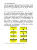
The figures below show two layouts for the 717. Note the fuselage nose and tailcone shapes.
Two-Class 717 configuration with 8 first-class seats with 36" pitch and 98 coach seats with 32" pitch.
Single-class 717 configuration with 117 seats at 32" and 31" pitch.
In addition to providing space for seats, galleys, lavatories, and emergency exits as set by regulations, the
aircraft layout is important for maintainence and studies are done early in the program to determine that
the layout is compatible with required ground services.
Aerodynamics
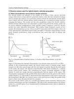
The fuselage shape must be such that separation and shock waves are avoided when possible. This
requires that the nose and tail cone fineness ratios be sufficiently large so that excessive flow
accelerations are avoided. Figure 2 shows the limit on nose fineness ratio set by the requirement for low
wave drag on the nose.
Even when the Mach number is low, constraints on fuselage pressure gradients limit nose fineness ratios
to values above about 1.5. The tail cone taper is chosen based on similar considerations and generally
falls in the range of 1.8 to 2.0. The details of fuselage shaping may be determined by looking at the
pressure distributions.
Several rules result from these analyses: The transition from nose to constant section, and constant
section to tail cone should be smooth - free of discontinuities in slope (kinks). The tail cone slopes should
resemble those shown in the examples. That is, the slope must change smoothly and the trailing edge
should not be blunt. The closure angle near the aft end should not be too large (half angle less than 14°-
20°).
Considerations Related to Fuselage Side-View
The shape of the fuselage in side view is determined based on visibility requirements for the cockpit and
ground clearance of the tail cone. Usually aft-fuselage upsweep is required to provide the capability of
rotating to high angles of attack on the ground (often about 14°). The upsweep cannot be set without
estimating the length of the main gear, but this can be done early in the design process by comparison
with similar aircraft.
Exercise 3: Fuselage Top View
Enter fuselage seating parameters.
About the input variables:
● Number of Seats: The total number of seats to be included at the specifed effective pitch.
● Seat Pitch: The average longitudinal distance between seats. This drawing includes only a single
seat pitch, while most aircraft will be divided into 2 or 3 classes with rather different seat pitch.
Use an efgfective value that produces the correct cabin length.
● Nose Fineness: The ratio of nose length to maximum diameter. The nose section is defined as the
section that extends from the forwardmost point on the aircraft to the maximum diameter section.
● Tailcone Fineness: The ratio of tailcone length to maximum diameter. The tailcone section is
defined as the section the end of the constant section to the aft end of the fuselage.
● Forward Extra Space: The distance (in feet for now) from the start of the constant section to the
first row of seats. This parameter is used to add extra space for galleys or closests, or may be
made negative if seats extend into the "nose" section of the fuselage.
● Aft Extra Space: The distance (in feet for now) from the end of the constant section to the last row
of seats. This parameter is used to add extra space for galleys or closests, or may be made
negative if seats extend into the tailcone section of the fuselage.
The layout is based on the cross-section geometry specified in exercise 2.
Fuselage and Seating-Related FARs
FAA Regulations Affecting Fuselage Design
A number of federal regulations have a major effect on the fuselage layout and sizing. Included here are
links to portions of FAR Part 25 that influence fuselage design.
Seating-Related Items
Emergency Egress
Emergency Demonstration
FARs Related to Seating
Sec. 25.815 Width of aisle.
The passenger aisle width at any point between seats must equal or exceed the values in the following
table:
Minimum
passenger
aisle width
(inches)
Less 25 in.
than and
Passenger 25 in. more
seating from from
capacity floor floor
10 or less /1/ 12 15
11 through 19 12 20
20 or more 15 20
/1/ A narrower width not less than 9
inches may be approved when
substantiated by tests found necessary
by the Administrator.
Sec. 25.817 Maximum number of seats abreast.
On airplanes having only one passenger aisle, no more than three seats abreast may be placed on each
side of the aisle in any one row.
Sec. 25.783 Doors.
(a) Each cabin must have at least one easily accessible external door.
(b) There must be a means to lock and safeguard each external door against opening in flight (either
inadvertently by persons or as a result of mechanical failure or failure of a single structural element either
during or after closure). Each external door must be openable from both the inside and the outside, even
though persons may be crowded against the door on the inside of the airplane. Inward opening doors may
be used if there are means to prevent occupants from crowding against the door to an extent that would
interfere with the opening of the door. The means of opening must be simple and obvious and must be
arranged and marked so that it can be readily located and operated, even in darkness. Auxiliary locking
devices may be used.
(c) Each external door must be reasonably free from jamming as a result of fuselage deformation in a
minor crash.
(d) Each external door must be located where persons using them will not be endangered by the
propellers when appropriate operating procedures are used.
(e) There must be a provision for direct visual inspection of the locking mechanism to determine if
external doors, for which the initial opening movement is not inward (including passenger, crew, service,
and cargo doors), are fully closed and locked. The provision must be discernible under operational
lighting conditions by appropriate crewmembers using a flashlight or equivalent lighting source. In
addition, there must be a visual warning means to signal the appropriate flight crewmembers if any
external door is not fully closed and locked. The means must be designed such that any failure or
combination of failures that would result in an erroneous closed and locked indication is improbable for
doors for which the initial opening movement is not inward.
(f) External doors must have provisions to prevent the initiation of pressurization of the airplane to an
unsafe level if the door is not fully closed and locked. In addition, it must be shown by safety analysis
that inadvertent opening is extremely improbable.
(g) Cargo and service doors not suitable for use as emergency exits need only meet paragraphs (e) and (f)
of this section and be safeguarded against opening in flight as a result of mechanical failure or failure of
a single structural element.
(h) Each passenger entry door in the side of the fuselage must qualify as a Type A, Type I, or Type II
passenger emergency exit and must meet the requirements of Secs. 25.807 through 25.813 that apply to
that type of passenger emergency exit.
(i) If an integral stair is installed in a passenger entry door that is qualified as a passenger emergency exit,
the stair must be designed so that under the following conditions the effectiveness of passenger
emergency egress will not be impaired:
(1) The door, integral stair, and operating mechanism have been subjected to the inertia forces specified
in Sec. 25.561(b)(3), acting separately relative to the surrounding structure.
(2) The airplane is in the normal ground attitude and in each of the attitudes corresponding to collapse of
one or more legs of the landing gear.
(j) All lavatory doors must be designed to preclude anyone from becoming trapped inside the lavatory,
and if a locking mechanism is installed, it be capable of being unlocked from the outside without the aid
of special tools.
Sec. 25.785 Seats, berths, safety belts, and harnesses.
(a) A seat (or berth for a nonambulant person) must be provided for each occupant who has reached his
or her second birthday.
(b) Each seat, berth, safety belt, harness, and adjacent part of the airplane at each station designated as
occupiable during takeoff and landing must be designed so that a person making proper use of these
facilities will not suffer serious injury in an emergency landing as a result of the inertia forces specified
in Secs. 25.561 and 25.562.
(c) Each seat or berth must be approved.
(d) Each occupant of a seat that makes more than an 18-degree angle with the vertical plane containing
the airplane centerline must be protected from head injury by a safety belt and an energy absorbing rest
that will support the arms, shoulders, head, and spine, or by a safety belt and shoulder harness that will
prevent the head from contacting any injurious object. Each occupant of any other seat must be protected
from head injury by a safety belt and, as appropriate to the type, location, and angle of facing of each
seat, by one or more of the following:
(1) A shoulder harness that will prevent the head from contacting any injurious object.
(2) The elimination of any injurious object within striking radius of the head.
(3) An energy absorbing rest that will support the arms, shoulders, head, and spine.
(e) Each berth must be designed so that the forward part has a padded end board, canvas diaphragm, or
equivalent means, that can withstand the static load reaction of the occupant when subjected to the
forward inertia force specified in Sec. 25.561. Berths must be free from corners and protuberances likely
to cause injury to a person occupying the berth during emergency conditions.
(f) Each seat or berth, and its supporting structure, and each safety belt or harness and its anchorage must
be designed for an occupant weight of 170 pounds, considering the maximum load factors, inertia forces,
and reactions among the occupant, seat, safety belt, and harness for each relevant flight and ground load
condition (including the emergency landing conditions prescribed in Sec. 25.561). In addition
(1) The structural analysis and testing of the seats, berths, and their supporting structures may be
determined by assuming that the critical load in the forward, sideward, downward, upward, and rearward
directions (as determined from the prescribed flight, ground, and emergency landing conditions) acts
separately or using selected combinations of loads if the required strength in each specified direction is
substantiated. The forward load factor need not be applied to safety belts for berths.
(2) Each pilot seat must be designed for the reactions resulting from the application of the pilot forces
prescribed in Sec. 25.395.
(3) The inertia forces specified in Sec. 25.561 must be multiplied by a factor of 1.33 (instead of the
fitting factor prescribed in Sec. 25.625) in determining the strength of the attachment of each seat to the
structure and each belt or harness to the seat or structure.
(g) Each seat at a flight deck station must have a restraint system consisting of a combined safety belt
and shoulder harness with a single-point release that permits the flight deck occupant, when seated with
the restraint system fastened, to perform all of the occupant's necessary flight deck functions. There must
be a means to secure each combined restraint system when not in use to prevent interference with the
operation of the airplane and with rapid egress in an emergency.
(h) Each seat located in the passenger compartment and designated for use during takeoff and landing by
a flight attendant required by the operating rules of this chapter must be:
(1) Near a required floor level emergency exit, except that another location is acceptable if the
emergency egress of passengers would be enhanced with that location. A flight attendant seat must be
located adjacent to each Type A emergency exit. Other flight attendant seats must be evenly distributed
among the required floor level emergency exits to the extent feasible.
(2) To the extent possible, without compromising proximity to a required floor level emergency exit,
located to provide a direct view of the cabin area for which the flight attendant is responsible.
(3) Positioned so that the seat will not interfere with the use of a passageway or exit when the seat is not
in use.
(4) Located to minimize the probability that occupants would suffer injury by being struck by items
dislodged from service areas, stowage compartments, or service equipment.
(5) Either forward or rearward facing with an energy absorbing rest that is designed to support the arms,
shoulders, head, and spine.
(6) Equipped with a restraint system consisting of a combined safety belt and shoulder harness unit with
a single point release. There must be means to secure each restraint system when not in use to prevent
interference with rapid egress in an emergency.
(i) Each safety belt must be equipped with a metal to metal latching device.
(j) If the seat backs do not provide a firm handhold, there must be a handgrip or rail along each aisle to
enable persons to steady themselves while using the aisles in moderately rough air.
(k) Each projecting object that would injure persons seated or moving about the airplane in normal flight
must be padded.
(l) Each forward observer's seat required by the operating rules must be shown to be suitable for use in
conducting the necessary enroute inspection.
FARs Related to Emergency Evacuation
Sec. 25.801 Ditching.
(a) If certification with ditching provisions is requested, the airplane must meet the requirements of this
section and Secs. 25.807(e), 25.1411, and 25.1415(a).
(b) Each practicable design measure, compatible with the general characteristics of the airplane, must be
taken to minimize the probability that in an emergency landing on water, the behavior of the airplane
would cause immediate injury to the occupants or would make it impossible for them to escape.
(c) The probable behavior of the airplane in a water landing must be investigated by model tests or by
comparison with airplanes of similar configuration for which the ditching characteristics are known.
Scoops, flaps, projections, and any other factor likely to affect the hydrodynamic characteristics of the
airplane, must be considered.
(d) It must be shown that, under reasonably probable water conditions, the flotation time and trim of the
airplane will allow the occupants to leave the airplane and enter the liferafts required by Sec. 25.1415. If
compliance with this provision is shown by buoyancy and trim computations, appropriate allowances
must be made for probable structural damage and leakage. If the airplane has fuel tanks (with fuel
jettisoning provisions) that can reasonably be expected to withstand a ditching without leakage, the
jettisonable volume of fuel may be considered as buoyancy volume.
(e) Unless the effects of the collapse of external doors and windows are accounted for in the investigation
of the probable behavior of the airplane in a water landing (as prescribed in paragraphs (c) and (d) of this
section), the external doors and windows must be designed to withstand the probable maximum local
pressures.
Sec. 25.803 Emergency evacuation.
(a) Each crew and passenger area must have emergency means to allow rapid evacuation in crash
landings, with the landing gear extended as well as with the landing gear retracted, considering the
possibility of the airplane being on fire.
(b) [Reserved]
(c) For airplanes having a seating capacity of more than 44 passengers, it must be shown that the
maximum seating capacity, including the number of crewmembers required by the operating rules for
which certification is requested, can be evacuated from the airplane to the ground under simulated
emergency conditions within 90 seconds. Compliance with this requirement must be shown by actual
demonstration using the test criteria outlined in
appendix J of this part unless the Administrator finds that
a combination of analysis and testing will provide data equivalent to that which would be obtained by
actual demonstration.
(d) [Reserved]
(e) [Reserved]
Sec. 25.807 Emergency exits.
(a) Type. For the purpose of this part, the types of exits are defined as follows:
(1) Type I. This type is a floor level exit with a rectangular opening of not less than 24 inches wide by 48
inches high, with corner radii not greater than one-third the width of the exit.
(2) Type II. This type is a rectangular opening of not less than 20 inches wide by 44 inches high, with
corner radii not greater than one-third the width of the exit. Type II exits must be floor level exits unless
located over the wing, in which case they may not have a step-up inside the airplane of more than 10
inches nor a step-down outside the airplane of more than 17 inches.
(3) Type III. This type is a rectangular opening of not less than 20 inches wide by 36 inches high, with
corner radii not greater than one-third the width of the exit, and with a step-up inside the airplane of not
more than 20 inches. If the exit is located over the wing, the step-down outside the airplane may not
exceed 27 inches.
(4) Type IV. This type is a rectangular opening of not less than 19 inches wide by 26 inches high, with
corner radii not greater than one-third the width of the exit, located over the wing, with a step-up inside
the airplane of not more than 29 inches and a step-down outside the airplane of not more than 36 inches.
(5) Ventral. This type is an exit from the passenger compartment through the pressure shell and the
bottom fuselage skin. The dimensions and physical configuration of this type of exit must allow at least
the same rate of egress as a Type I exit with the airplane in the normal ground attitude, with landing gear
extended.
(6) Tail cone. This type is an aft exit from the passenger compartment through the pressure shell and
through an openable cone of the fuselage aft of the pressure shell. The means of opening the tailcone
must be simple and obvious and must employ a single operation.
(7) Type A. This type is a floor level exit with a rectangular opening of not less than 42 inches wide by
72 inches high with corner radii not greater than one-sixth of the width of the exit.
(b) Step down distance. Step down distance, as used in this section, means the actual distance between
the bottom of the required opening and a usable foot hold, extending out from the fuselage, that is large
enough to be effective without searching by sight or feel.
(c) Over-sized exits. Openings larger than those specified in this section, whether or not of rectangular
shape, may be used if the specified rectangular opening can be inscribed within the opening and the base
of the inscribed rectangular opening meets the specified step-up and step-down heights.
(d) Passenger emergency exits. Except as provided in paragraphs (d) (3) through (7) of this section, the
minimum number and type of passenger emergency exits is as follows:
(1) For passenger seating configurations of 1 through 299 seats:
Emergency exits for
each side of the
fuselage
Passenger
seating
configuration
(crewmember
seats not Type Type Type Type
included) I II III IV
1 through 9 1
10 through 19 1
20 through 39 1 1
40 through 79 1 1
80 through 109 1 2
110 through 139 2 1
140 through 179 2 2
Additional exits are required for passenger seating configurations greater than 179 seats in accordance
with the following table:
Additional
emergency Increase in
exits passenger
(each side seating
of configuration
fuselage) allowed
Type A 110
Type I 45
Type II 40
Type III 35
(2) For passenger seating configurations greater than 299 seats, each emergency exit in the side of the
fuselage must be either a Type A or Type I. A passenger seating configuration of 110 seats is allowed for
each pair of Type A exits and a passenger seating configuration of 45 seats is allowed for each pair of
Type I exits.
(3) If a passenger ventral or tail cone exit is installed and that exit provides at least the same rate of
egress as a Type III exit with the airplane in the most adverse exit opening condition that would result
from the collapse of one or more legs of the landing gear, an increase in the passenger seating
configuration beyond the limits specified in paragraph (d) (1) or (2) of this section may be allowed as
follows:
(i) For a ventral exit, 12 additional passenger seats.
(ii) For a tail cone exit incorporating a floor level opening of not less than 20 inches wide by 60 inches
high, with corner radii not greater than one-third the width of the exit, in the pressure shell and
incorporating an approved assist means in accordance with Sec. 25.809(h), 25 additional passenger seats.
(iii) For a tail cone exit incorporating an opening in the pressure shell which is at least equivalent to a
Type III emergency exit with respect to dimensions, step-up and step-down distance, and with the top of
the opening not less than 56 inches from the passenger compartment floor, 15 additional passenger seats.
(4) For airplanes on which the vertical location of the wing does not allow the installation of overwing
exits, an exit of at least the dimensions of a Type III exit must be installed instead of each Type IV exit
required by subparagraph (1) of this paragraph.
(5) An alternate emergency exit configuration may be approved in lieu of that specified in paragraph (d)
(1) or (2) of this section provided the overall evacuation capability is shown to be equal to or greater than
that of the specified emergency exit configuration.
(6) The following must also meet the applicable emergency exit requirements of Secs. 25.809 through
25.813:
(i) Each emergency exit in the passenger compartment in excess of the minimum number of required
emergency exits.
(ii) Any other floor level door or exit that is accessible from the passenger compartment and is as large or
larger than a Type II exit, but less than 46 inches wide.
(iii) Any other passenger ventral or tail cone exit.
(7) For an airplane that is required to have more than one passenger emergency exit for each side of the
fuselage, no passenger emergency exit shall be more than 60 feet from any adjacent passenger
emergency exit on the same side of the same deck of the fuselage, as measured parallel to the airplane's
longitudinal axis between the nearest exit edges.
(e) Ditching emergency exits for passengers. Ditching emergency exits must be provided in accordance
with the following requirements whether or not certification with ditching provisions is requested:
(1) For airplanes that have a passenger seating configuration of nine seats or less, excluding pilots seats,
one exit above the waterline in each side of the airplane, meeting at least the dimensions of a Type IV
exit.
(2) For airplanes that have a passenger seating configuration of 10 seats or more, excluding pilots seats,
one exit above the waterline in a side of the airplane, meeting at least the dimensions of a Type III exit
for each unit (or part of a unit) of 35 passenger seats, but no less than two such exits in the passenger
cabin, with one on each side of the airplane. The passenger seat/exit ratio may be increased through the
use of larger exits, or other means, provided it is shown that the evacuation capability during ditching has
been improved accordingly.
(3) If it is impractical to locate side exits above the waterline, the side exits must be replaced by an equal
number of readily accessible overhead hatches of not less than the dimensions of a Type III exit, except
that for airplanes with a passenger configuration of 35 seats or less, excluding pilots seats, the two
required Type III side exits need be replaced by only one overhead hatch.
(f) Flightcrew emergency exits. For airplanes in which the proximity of passenger emergency exits to the
flightcrew area does not offer a convenient and readily accessible means of evacuation of the flightcrew,
and for all airplanes having a passenger seating capacity greater than 20, flightcrew exits shall be located
in the flightcrew area. Such exits shall be of sufficient size and so located as to permit rapid evacuation
by the crew. One exit shall be provided on each side of the airplane; or, alternatively, a top hatch shall be
provided. Each exit must encompass an unobstructed rectangular opening of at least 19 by 20 inches
unless satisfactory exit utility can be demonstrated by a typical crewmember.
Sec. 25.809 Emergency exit arrangement.
(a) Each emergency exit, including a flight crew emergency exit, must be a movable door or hatch in the
external walls of the fuselage, allowing unobstructed opening to the outside.
(b) Each emergency exit must be openable from the inside and the outside except that sliding window
emergency exits in the flight crew area need not be openable from the outside if other approved exits are
convenient and readily accessible to the flight crew area. Each emergency exit must be capable of being
opened, when there is no fuselage deformation
(1) With the airplane in the normal ground attitude and in each of the attitudes corresponding to collapse
of one or more legs of the landing gear; and
(2) Within 10 seconds measured from the time when the opening means is actuated to the time when the
exit is fully opened.
(c) The means of opening emergency exits must be simple and obvious and may not require exceptional
effort. Internal exit-opening means involving sequence operations (such as operation of two handles or
latches or the release of safety catches) may be used for flight crew emergency exits if it can be
reasonably established that these means are simple and obvious to crewmembers trained in their use.
(d) If a single power-boost or single power-operated system is the primary system for operating more
than one exit in an emergency, each exit must be capable of meeting the requirements of paragraph (b) of
this section in the event of failure of the primary system. Manual operation of the exit (after failure of the
primary system) is acceptable.
(e) Each emergency exit must be shown by tests, or by a combination of analysis and tests, to meet the
requirements of paragraphs (b) and (c) of this section.
(f) There must be a means to lock each emergency exit and to safeguard against its opening in flight,
either inadvertently by persons or as a result of mechanical failure. In addition, there must be a means for
direct visual inspection of the locking mechanism by crewmembers to determine that each emergency
exit, for which the initial opening movement is outward, is fully locked.
(g) There must be provisions to minimize the probability of jamming of the emergency exits resulting
from fuselage deformation in a minor crash landing.
(h) When required by the operating rules for any large passenger-carrying turbojet-powered airplane,
each ventral exit and tailcone exit must be
(1) Designed and constructed so that it cannot be opened during flight; and
(2) Marked with a placard readable from a distance of 30 inches and installed at a conspicuous location
near the means of opening the exit, stating that the exit has been designed and constructed so that it
cannot be opened during flight.
Sec. 25.810 Emergency egress assist means and escape routes.
(a) Each nonoverwing landplane emergency exit more than 6 feet from the ground with the airplane on
the ground and the landing gear extended and each nonoverwing Type A exit must have an approved
means to assist the occupants in descending to the ground.
(1) The assisting means for each passenger emergency exit must be a self- supporting slide or equivalent;
and, in the case of a Type A exit, it must be capable of carrying simultaneously two parallel lines of
evacuees. In addition, the assisting means must be designed to meet the following requirements:
(i) It must be automatically deployed and deployment must begin during the interval between the time
the exit opening means is actuated from inside the airplane and the time the exit is fully opened.
However, each passenger emergency exit which is also a passenger entrance door or a service door must
be provided with means to prevent deployment of the assisting means when it is opened from either the
inside or the outside under nonemergency conditions for normal use.
(ii) It must be automatically erected within 10 seconds after deployment is begun.
(iii) It must be of such length after full deployment that the lower end is self-supporting on the ground
and provides safe evacuation of occupants to the ground after collapse of one or more legs of the landing
gear.
(iv) It must have the capability, in 25-knot winds directed from the most critical angle, to deploy and,
with the assistance of only one person, to remain usable after full deployment to evacuate occupants
safely to the ground.
(v) For each system installation (mockup or airplane installed), five consecutive deployment and inflation
tests must be conducted (per exit) without failure, and at least three tests of each such five-test series
must be conducted using a single representative sample of the device. The sample devices must be
deployed and inflated by the system's primary means after being subjected to the inertia forces specified
in Sec. 25.561(b). If any part of the system fails or does not function properly during the required tests,
the cause of the failure or malfunction must be corrected by positive means and after that, the full series
of five consecutive deployment and inflation tests must be conducted without failure.
(2) The assisting means for flightcrew emergency exits may be a rope or any other means demonstrated
to be suitable for the purpose. If the assisting means is a rope, or an approved device equivalent to a rope,
it must be
(i) Attached to the fuselage structure at or above the top of the emergency exit opening, or, for a device at
a pilot's emergency exit window, at another approved location if the stowed device, or its attachment,
would reduce the pilot's view in flight;
(ii) Able (with its attachment) to withstand a 400-pound static load.
(b) Assist means from the cabin to the wing are required for each Type A exit located above the wing and
having a stepdown unless the exit without an assist means can be shown to have a rate of passenger
egress at least equal to that of the same type of nonoverwing exit. If an assist means is required, it must
be automatically deployed and automatically erected, concurrent with the opening of the exit and self-
supporting within 10 seconds.
(c) An escape route must be established from each overwing emergency exit, and (except for flap
surfaces suitable as slides) covered with a slip resistant surface. Except where a means for channeling the
flow of evacuees is provided
(1) The escape route must be at least 42 inches wide at Type A passenger emergency exits and must be at
least 2 feet wide at all other passenger emergency exits, and
(2) The escape route surface must have a reflectance of at least 80 percent, and must be defined by
markings with a surface-to-marking contrast ratio of at least 5:1.
(d) If the place on the airplane structure at which the escape route required in paragraph (c) of this
section terminates, is more than 6 feet from the ground with the airplane on the ground and the landing
gear extended, means to reach the ground must be provided to assist evacuees who have used the escape
route. If the escape route is over a flap, the height of the terminal edge must be measured with the flap in
the takeoff or landing position, whichever is higher from the ground. The assisting means must be usable
and self-supporting with one or more landing gear legs collapsed and under a 25-knot wind directed from
the most critical angle. The assisting means provided for each escape route leading from a Type A
emergency exit must be capable of carrying simultaneously two parallel lines of evacuees. For other than
Type A exits, the assist means must be capable of carrying simultaneously as many parallel lines of
evacuees as there are required escape routes.
Sec. 25.813 Emergency exit access.
Each required emergency exit must be accessible to the passengers and located where it will afford an
effective means of evacuation. Emergency exit distribution must be as uniform as practical, taking
passenger distribution into account; however, the size and location of exits on both sides of the cabin
need not be symmetrical. If only one floor level exit per side is prescribed, and the airplane does not have
a tail cone or ventral emergency exit, the floor level exit must be in the rearward part of the passenger
compartment, unless another location affords a more effective means of passenger evacuation. Where
more than one floor level exit per side is prescribed, at least one floor level exit per side must be located
near each end of the cabin, except that this provision does not apply to combination cargo/passenger
configurations. In addition
(a) There must be a passageway leading from the nearest main aisle to each Type I, Type II, or Type A
emergency exit and between individual passenger areas. Each passageway leading to a Type A exit must
be unobstructed and at least 36 inches wide. Passageways between individual passenger areas and those
leading to Type I and Type II emergency exits must be unobstructed and at least 20 inches wide. Unless
there are two or more main aisles, each Type A exit must be located so that there is passenger flow along
the main aisle to that exit from both the forward and aft directions. If two or more main aisles are
provided, there must be unobstructed cross-aisles at least 20 inches wide between main aisles. There
must be
(1) A cross-aisle which leads directly to each passageway between the nearest main aisle and a Type A
exit; and
(2) A cross-aisle which leads to the immediate vicinity of each passageway between the nearest main
aisle and a Type 1, Type II, or Type III exit; except that when two Type III exits are located within three
passenger rows of each other, a single cross-aisle may be used if it leads to the vicinity between the
passageways from the nearest main aisle to each exit.
(b) Adequate space to allow crewmember(s) to assist in the evacuation of passengers must be provided as
follows:
(1) The assist space must not reduce the unobstructed width of the passageway below that required for
the exit.
(2) For each Type A exit, assist space must be provided at each side of the exit regardless of whether the
exit is covered by Sec. 25.810(a).
(3) For any other type exit that is covered by Sec. 25.810(a), space must at least be provided at one side
of the passageway.
(c) The following must be provided for each Type III or Type IV exit (1) There must be access from the
nearest aisle to each exit. In addition, for each Type III exit in an airplane that has a passenger seating
configuration of 60 or more
(i) Except as provided in paragraph (c)(1)(ii), the access must be provided by an unobstructed
passageway that is at least 10 inches in width for interior arrangements in which the adjacent seat rows
on the exit side of the aisle contain no more than two seats, or 20 inches in width for interior
arrangements in which those rows contain three seats. The width of the passageway must be measured
with adjacent seats adjusted to their most adverse position. The centerline of the required passageway
width must not be displaced more than 5 inches horizontally from that of the exit.
(ii) In lieu of one 10- or 20-inch passageway, there may be two passageways, between seat rows only,
that must be at least 6 inches in width and lead to an unobstructed space adjacent to each exit. (Adjacent
exits must not share a common passageway.) The width of the passageways must be measured with
adjacent seats adjusted to their most adverse position. The unobstructed space adjacent to the exit must
extend vertically from the floor to the ceiling (or bottom of sidewall stowage bins), inboard from the exit
for a distance not less than the width of the narrowest passenger seat installed on the airplane, and from
the forward edge of the forward passageway to the aft edge of the aft passageway. The exit opening must
be totally within the fore and aft bounds of the unobstructed space.
(2) In addition to the access
(i) For airplanes that have a passenger seating configuration of 20 or more, the projected opening of the
exit provided must not be obstructed and there must be no interference in opening the exit by seats,
berths, or other protrusions (including any seatback in the most adverse position) for a distance from that
exit not less than the width of the narrowest passenger seat installed on the airplane.
(ii) For airplanes that have a passenger seating configuration of 19 or fewer, there may be minor
obstructions in this region, if there are compensating factors to maintain the effectiveness of the exit.
(3) For each Type III exit, regardless of the passenger capacity of the airplane in which it is installed,
there must be placards that
(i) Are readable by all persons seated adjacent to and facing a passageway to the exit;
(ii) Accurately state or illustrate the proper method of opening the exit, including the use of handholds;
and
(iii) If the exit is a removable hatch, state the weight of the hatch and indicate an appropriate location to
place the hatch after removal.
(d) If it is necessary to pass through a passageway between passenger compartments to reach any
required emergency exit from any seat in the passenger cabin, the passageway must be unobstructed.
However, curtains may be used if they allow free entry through the passageway.
(e) No door may be installed in any partition between passenger compartments.
(f) If it is necessary to pass through a doorway separating the passenger cabin from other areas to reach
any required emergency exit from any passenger seat, the door must have a means to latch it in open
position. The latching means must be able to withstand the loads imposed upon it when the door is
subjected to the ultimate inertia forces, relative to the surrounding structure, listed in Sec. 25.561(b).