kelly l murdock 3ds Max 2009 Bible phần 5 pdf
Bạn đang xem bản rút gọn của tài liệu. Xem và tải ngay bản đầy đủ của tài liệu tại đây (5.81 MB, 108 trang )
FIGURE 19.13
Several frames of an animation showing a tree scene from sunrise to sunset
Using Volume Lights
When light shines through fog, smoke, or dust, the beam of the light becomes visible. The effect is known
as a Volume Light. To add a Volume Light to a scene, choose Rendering ➪ Environment (or press the 8 key)
to open the Environment dialog box. Then click the Add button in the Atmosphere rollout to open the Add
Atmospheric Effect dialog box, and select Volume Light. The parameters for the volume light are presented
in the Volume Light Parameters rollout.
You can also access the Volume Light effect from the Atmospheres and Effects rollout in the Modify panel
when a light is selected.
Chapter 45, “Using Atmospheric and Render Effects,” covers the other atmospheric effects.
Volume light parameters
At the top of the Volume Light Parameters rollout, shown in Figure 19.14, is a Pick Light button, which
enables you to select a light to apply the effect to. You can select several lights, which then appear in a drop-
down list. You can remove lights from this list with the Remove Light button.
CROSS-REF
CROSS-REF
500
Materials, Cameras, and Lighting Basics
Part IV
26_381304-ch19.qxp 7/7/08 2:46 PM Page 500
FIGURE 19.14
The Volume Light Parameters rollout in the Environment dialog box lets you choose which lights to include in the
effect.
In the Volume section, the Fog Color swatch lets you select a color for the fog that is seen within the light.
This color is combined with the color of the light. The Attenuation Color is the color the fog appears to
have at a distance far from the light source. This color also combines with the Fog Color and is best set to a
dark color.
The Density value determines the thickness of the fog. The Exponential option causes the density to
increase exponentially with the distance. The Max and Min Light Percentage values determine the amount
of glow that the volume light causes, and the Attenuation Multiplier controls the strength of the attenuation
color.
You have four options for filtering shadows: Low, Medium, High, and Use Light Smp Range. The Low
option renders shadows quickly but isn’t very accurate. The High option takes a while but produces the
best quality. The Use Light Smp Range option bases the filtering on the Sample Volume value and can be set
to Auto. The Sample Volume can range from 1 to 10,000. The Low option has a Sample Volume value of 8;
Medium, 25; and High, 50.
Only Shadow Map type shadows cast shadows through volume fog.
The Start and End Attenuation values are percentages of the Start and End range values for the light’s atten-
uation. These values have an impact only if attenuation is turned on for the light.
The Noise settings help to determine the randomness of Volume Light. Noise effects can be turned on and
given an Amount. You can also Link the noise to the light instead of using world coordinates. Noise types
NOTE
NOTE
501
Using Lights and Basic Lighting Techniques
19
26_381304-ch19.qxp 7/7/08 2:46 PM Page 501
include Regular, Fractal, and Turbulence. Another option inverts the noise pattern. The Noise Threshold
limits the effect of noise. Wind settings affect how the light moves as determined by the wind’s direction,
Wind Strength, and Phase.
Figure 19.15 shows several volume light possibilities. The left image includes the Volume Light effect, the
middle image enables shadows, and the right image includes some Turbulent Noise.
FIGURE 19.15
The Volume Light effect makes the light visible.
Tutorial: Showing car headlights
One popular way to use volume lights is to display the headlights of cars. For this tutorial, you’re going to
use the Delfino Feroce 2001 car model created by Viewpoint Datalabs.
To display the headlights of a car, follow these steps:
1. Open the Car headlights.max file from the Chap 19 directory on the DVD.
This file includes a model of a car.
2. Select the Create ➪ Lights ➪ Standard Lights ➪ Target Spotlight menu command, and drag in the
Left viewport to create a spotlight object. Select and move the spotlight and the target to be posi-
tioned to look as if a light is shining out from the left headlight.
3. Open the Modify panel, and in the Spotlight Parameters rollout, set the Hotspot value to 20, the
Falloff to 25, and in the Intensity/Color/Attenuation rollout, set the Decay setting to Inverse
Square with a Start value of 3.0. In the Atmospheres and Effects rollout, click the Add button,
select Volume Light from the Add Atmosphere or Effect dialog box that appears, and click OK.
When a light is added to the scene, the default lights are automatically turned off. To provide
any additional lighting, add some Omni lights above the car.
4. Select the Volume Light effect in the list within the Atmospheres and Effects rollout, and click the
Setup button. The Environment dialog box opens, in which you can edit the Volume Light
parameters for the newly created light. Set the Density value to 100.
5. Now create three more headlights. To do this, select both the first spotlight object and its target,
and create a cloned copy by holding down the Shift key while moving it toward the right head-
light. Position the other spotlights so that they shine outward from the other headlights.
Figure 19.16 shows the resulting car with its headlights illuminated.
NOTE
NOTE
502
Materials, Cameras, and Lighting Basics
Part IV
26_381304-ch19.qxp 7/7/08 2:46 PM Page 502
FIGURE 19.16
The car now has headlights, thanks to spotlights and the Volume Light effect.
Tutorial: Creating laser beams
Laser beams are extremely useful lights. From your CD-ROM drive to your laser printer, lasers are found
throughout a modern-day office. They also are great to use in fantasy and science fiction images. You can
easily create laser beams using direct lights and the Volume Light effect. In this tutorial, you’ll add some
lasers to the spaceship model created by Viewpoint Datalabs.
To add some laser beams to a scene, follow these steps:
1. Open the Spaceship laser.max file from the Chap 19 directory on the DVD.
This file includes a spaceship model.
2. Select the Create ➪ Lights ➪ Standard Lights ➪ Directional menu command, and add a Free Direct
light to the end of one of the laser guns in the Front viewport. Scale the light down until the
cylinder is the size of the desired laser beam and rotate it so it points away from the laser beam.
3. With the light selected, open the Modify panel. In the Atmospheres and Effects rollout, click the
Add button and double-click the Volume Light selection. Then select the Volume Light option in
the list, and click the Setup button to open the Environment dialog box. Change the Fog Color to
red and the Density value to 50 and make sure that the Use Attenuation Color is disabled.
4. With the direct lights added to the scene, the default lights are deactivated, so you need to add
some Omni lights above the spaceship to illuminate it. To do this, select the Create ➪ Lights ➪
Standard Lights ➪ Omni menu command, and click above the spaceship in the Front view three
times to create three lights. Set the Multiplier on the first light to 1.0, and position it directly
above the spaceship. Set the other two lights to 0.5, and position them on either side of the space-
ship and lower than the first light.
Figure 19.17 shows the resulting laser beams shooting forth from the spaceship.
503
Using Lights and Basic Lighting Techniques
19
26_381304-ch19.qxp 7/7/08 2:46 PM Page 503
FIGURE 19.17
You can create laser beams using direct lights and the Volume Light effect.
Using projector maps and raytraced shadows
If a map is added to a light in the Parameters rollout, the light becomes a projector. Projector maps can be
simple images, animated images, or black-and-white masks to cast shadows. To load a projector map, select
a light and open the Modify panel. Under the Spotlight Parameters rollout, click the Projector Map button
and select the map to use from the Material/Map Browser.
Raytraced shadows take longer to render than the Shadow Maps or Area Shadows option, but the shadows
always have a hard edge and are an accurate representation of the object.
You can create shadows for wireframe objects with transparency only by using raytraced shadows.
In the Shadow Parameters rollout, you can select whether shadows are computed using
shadow maps or raytraced shadows. Using the latter selection lets you project a transparent object’s color
onto the shadow.
Tutorial: Projecting a trumpet image on a scene
As an example of a projector light, you create a musical scene with several musical notes and project the
image of a trumpet on them.
To project an image onto a rendered scene, follow these steps:
1. Open the Trumpet mask.max file from the Chap 19 directory on the DVD.
This file includes a trumpet model shown in the maximized Left viewport. This file is used to gen-
erate a project map.
NOTE
NOTE
504
Materials, Cameras, and Lighting Basics
Part IV
26_381304-ch19.qxp 7/7/08 2:46 PM Page 504
2. Choose Rendering ➪ Render (or press the F10 key) to open the Render dialog box; set the resolu-
tion to 640 × 480, and select the Left viewport. Then select the Render Elements tab, and click
the Add button. Select Alpha from the Render Elements dialog box, click OK, and then click the
Render button. The side view of the trumpet in the Rendered Frame Window renders along with
an alpha channel rendering of the trumpet. When the rendering completes, click the Save File
button in the Rendered Frame Window for the alpha channel and save the file as trumpet
mask.tif.
3. Open the Musical notes.max file from the Chap 19 directory on the DVD.
This file contains several musical notes created from primitive objects.
4. Select the Create ➪ Lights ➪ Standard Lights ➪ Target Spotlight menu command, and drag to cre-
ate two lights in the Top viewport. Position the first spotlight to be perpendicular to the scene and
to shine down on it from above.
5. Open the Modify panel; in the Advanced Effects rollout, click the Projector Map button and double-
click Bitmap from the Material/Map Browser. Locate and select the Trumpet Mask.tif file, and click
Open. This projects a silhouette of a trumpet onto the scene. Use the second spotlight to light the
music notes.
Figure 19.18 shows the musical notes with the trumpet projection map.
FIGURE 19.18
You can use projection maps to project an image in the scene, like this trumpet.
505
Using Lights and Basic Lighting Techniques
19
26_381304-ch19.qxp 7/7/08 2:46 PM Page 505
Tutorial: Creating a stained-glass window
When a light that uses raytraced shadows shines through an object with transparent materials, the Filter
color of the material is projected onto objects behind. In this tutorial, you create a stained-glass window
and shine a light through it using raytraced shadows.
To create a stained-glass window, follow these steps:
1. Open the Stained glass window.max file from the Chap 19 directory on the DVD.
This file includes a stained-glass window for a fish market. (Don’t ask me why a fish market has a
stained-glass window.)
2. Select the Create ➪ Lights ➪ Standard Lights ➪ Target Spotlight menu command, and drag in the
Left view from a position to the right and above the window to the window.
This creates a target spotlight that shines through the stained-glass window onto the floor behind it.
3. In the General Parameters rollout, make sure that the On option is enabled in the Shadows sec-
tion and select Ray Traced Shadows from the drop-down list.
Figure 19.19 shows the stained-glass window with the colored shadow cast on the scene floor.
FIGURE 19.19
A stained-glass window effect created with raytraced shadows
506
Materials, Cameras, and Lighting Basics
Part IV
26_381304-ch19.qxp 7/7/08 2:46 PM Page 506
Summary
I hope you have found this chapter enlightening. (Sorry about the bad pun, but I need to work them in
where I can.) Max has many different lights, each with plenty of controls. Learning to master these controls
can take you a long way toward increasing the realism of the scene. In this chapter, you’ve accomplished the
following:
Learned the basics of lighting
Discovered Max’s standard and photometric light types
Created and positioned light objects
Learned to change the viewport view to a light
Used the Sunlight and Daylight systems
Used the Volume Light atmospheric effect
Added projection maps to lights
Used raytraced shadows to create a stained-glass window
In the next chapter you finally start animating objects, beginning with the basics, including keyframing.
507
Using Lights and Basic Lighting Techniques
19
26_381304-ch19.qxp 7/7/08 2:46 PM Page 507
26_381304-ch19.qxp 7/7/08 2:46 PM Page 508
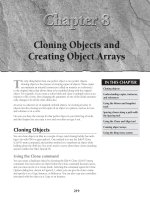
Animation and
Rendering Basics
IN THIS PART
Chapter 20
Understanding Animation and
Keyframe Basics
Chapter 21
Animating with Constraints and
Controllers
Chapter 22
Learning to Render a Scene
27_381304-pp05.qxp 7/7/08 2:54 PM Page 509
27_381304-pp05.qxp 7/7/08 2:54 PM Page 510
M
ax can be used to create some really amazing images, but I bet more of
you go to the movies than go to see images in a museum. The differ-
ence is in seeing moving images versus static images.
In this chapter, I start discussing what is probably one of the main reasons you
decided to learn 3ds Max in the first place — animation. Max includes many dif-
ferent features to create animations. This chapter covers the easiest and most
basic of these features — keyframe animation.
Along the way, you’ll examine all the various controls that are used to create, edit,
and control animation keys, including the Time Controls, the Track Bar, and the
Motion panel. Keyframes can be used to animate object transformations, but they
also can be used to animate other parameters such as materials. If you get fin-
ished with this chapter in time, you may have time to watch a movie.
Using the Time Controls
Before jumping into animation, you need to understand the controls that make it
possible. These controls collectively are called the Time Controls and can be
found on the lower interface bar between the key controls and the Viewport
Navigation Controls. The Time Controls also include the Time Slider found
directly under the viewports.
The Time Slider provides an easy way to move through the frames of an anima-
tion. To do this, just drag the Time Slider button in either direction. The Time
Slider button is labeled with the current frame number and the total number of
frames. The arrow buttons on either side of this button work the same as the
Previous and Next Frame (Key) buttons.
The Time Control buttons include buttons to jump to the Start or End of the ani-
mation, or to step forward or back by a single frame. You can also jump to an
511
IN THIS CHAPTER
Controlling time
Using the animation mode
buttons to create keys
Using the Track Bar
Viewing and editing key values
Using the Motion panel
and trajectories
Enabling ghosting
Setting animation preferences
Animating materials
Creating previews
Understanding Animation
and Keyframe Basics
28_381304-ch20.qxp 7/7/08 2:42 PM Page 511
exact frame by entering the frame number in the frame number field. The Time Controls are presented in
Table 20.1.
TABLE 20.1
Time Controls
Toolbar Button Name Description
Go to Start Sets the time to frame 1.
Previous Frame/Key Decreases the time by one frame or selects the
previous key.
Play Animation, Play Selected Cycles through the frames; this button becomes a Stop
button when an animation is playing.
Next Frame/Key Advances the time by one frame or selects the next key.
Go to End Sets the time to the final frame.
Key Mode Toggle Toggles between key and frame modes; with Key Mode
on, the icon turns light blue and the Previous Frame
and Next Frame buttons change to Previous Key and
Next Key.
Current Frame field Indicates the current frame; a frame number can be
typed in this field for more exact control than the Time
Slider.
Time Configuration Opens the Time Configuration dialog box where settings
like frame rate, time display, and animation length can
be set.
The default scene starts with 100 frames, but this is seldom what you actually need. You can change the
number of frames at any time by clicking the Time Configuration button, which is to the right of the frame
number field. Clicking this button opens the Time Configuration dialog box, shown in Figure 20.1. You can
also access this dialog box by right-clicking any of the Time Control buttons.
Setting frame rate
Within this dialog box, you can set several options, including the Frame Rate. Frame rate provides the con-
nection between the number of frames and time. It is measured in frames per second. The options include
standard frame rates such as NTSC (National Television Standards Committee, around 30 frames per sec-
ond), Film (around 24 frames per second), and PAL (Phase Alternate Line, used by European countries,
around 25 frames per second), or you can select Custom and enter your own frame rate.
The Time Display section lets you set how time is displayed on the Time Slider. The options include
Frames, SMPTE (Society of Motion Picture Technical Engineers), Frame:Ticks, or MM:SS:Ticks (Minutes
and Seconds). SMPTE is a standard time measurement used in video and television. A Tick is
1
⁄4800 of
a second.
512
Animation and Rendering Basics
Part V
28_381304-ch20.qxp 7/7/08 2:42 PM Page 512
FIGURE 20.1
The Time Configuration dialog box lets you set the number of frames to include in a scene.
Setting speed and direction
The Playback section sets options for how the animation sequence is played back. The Real Time option
skips frames to maintain the specified frame rate. The Active Viewport Only option causes the animation to
play only in a single viewport, which speeds up the animation. The Loop option repeats the animation over
and over. The Loop option is available only if the Real Time option is disabled. If the Loop option is set,
then you can specify the Direction as Forward, Reverse, or Ping-Pong (which repeats playing forward and
then reverse). The Speed setting can be
1
/4,
1
/2, 1, 2, or 4 times normal.
The Time Configuration dialog box also lets you specify the Start Time, End Time, Length, and Current
Time values. These values are all interrelated, so setting the Length and the Start Time, for example, auto-
matically changes the End Time. These values can be changed at any time without destroying any keys. For
example, if you have an animation of 500 frames and you set the Start and End Time to 30 and 50, the
Time Slider controls only those 21 frames. Keys before or after this time are still available and can be
accessed by resetting the Start and End Time values to 0 and 500.
The Re-scale Time button fits all the keys into the active time segment by stretching or shrinking the num-
ber of frames between keys. You can use this feature to resize the animation to the number of frames
defined by Start and End Time values.
The Key Steps group lets you set which key objects are navigated using key mode. If you select Use Track
Bar, key mode moves through only the keys on the Track Bar. If you select the Selected Objects Only
option, key mode jumps only to the keys for the currently selected object. You can also filter to move
between Position, Rotation, and Scale keys. The Use Current Transform option locates only those keys that
are the same as the current selected transform button.
513
Understanding Animation and Keyframe Basics
20
28_381304-ch20.qxp 7/7/08 2:42 PM Page 513
Using Time Tags
To the right of the Prompt Line is a field marked Add Time Tag. Clicking this field pops up a menu with
options to Add or Edit a Time Tag. Time Tags can be set for each frame in the scene. Once set, the Time
Tags are visible in the Time Tag field whenever that time is selected.
Working with Keys
It isn’t just a coincidence that the largest button in the entire Max interface has a key on it. Creating and
working with keys is how animations are accomplished. Keys define a particular state of an object at a par-
ticular time. Animations are created as the object moves or changes between two different key states.
Complex animations can be generated with only a handful of keys.
You can create keys in numerous ways, but the easiest is with the Key Controls found on the lower interface
bar. These controls are located to the left of the Time Controls. Table 20.2 displays and explains all these
controls. Closely related to the Key Controls is the Track Bar, which is located under the Time Slider.
TABLE 20.2
Key Controls
Toolbar Button Name Description
Set Key (K) Creates animation keys in Set Key mode
Toggle Auto Key Mode (N) Sets keys automatically for the selected object when
enabled
Toggle Set Key Mode (') Sets keys as specified by the key filters for the
selected object when enabled
Selection Set drop-down list Specifies a selection set to use for the given keys
Default In/Out Tangents Assigns the default tangents that are used on
for New Keys all new keys
Open Filters Dialog box Contains pop-up options for the filtering keys
Max includes two animation modes: Auto Key (N) and Set Key ('). You can select either of these modes by
clicking the respective buttons at the bottom of the interface. When active, the button turns bright red, and
the border around the active viewport also turns red to remind you that you are in animate mode. Red also
appears around a spinner for any animated parameters.
Auto Key mode
With the Auto Key button enabled, every transformation or parameter change creates a key that defines
where and how an object should look at that specific frame.
514
Animation and Rendering Basics
Part V
28_381304-ch20.qxp 7/7/08 2:42 PM Page 514
To create a key, drag the Time Slider to a frame where you want to create a key and then move the selected
object or change the parameter, and a key is automatically created. When the first key is created, Max auto-
matically goes back and creates a key for frame 0 that holds the object’s original position or parameter.
Upon setting the key, Max then interpolates all the positions and changes between the keys. The keys are
displayed in the Track Bar.
Each frame can hold several different keys, but only one for each type of transform and each parameter. For
example, if you move, rotate, scale, and change the Radius parameter for a sphere object with the Auto Key
mode enabled, then separate keys are created for position, rotation, scaling, and a parameter change.
Set Key mode
The Set Key button (') offers more control over key creation and sets keys only when you click the Set Key
button (K). It also creates keys only for the key types enabled in the Key Filters dialog box. You can open
the Key Filters dialog box, shown in Figure 20.2, by clicking the Key Filters button. Available key types
include All, Position, Rotation, Scale, IK Parameters, Object Parameters, Custom Attributes, Modifiers,
Materials, and Other (which allows keys to be set for manipulator values).
FIGURE 20.2
Use the Set Key Filters dialog box to specify the types of keys to create.
Tutorial: Rotating a windmill’s blades
The best way to learn is to practice, and there’s no better time to practice than now. For this quick example,
you animate a set of blades on a windmill.
To animate a set of windmill blades rotating, follow these steps:
1. Open the Rotating windmill blades.max file from the Chap 20 directory on the DVD.
This file includes a windmill model created by Viewpoint Datalabs.
2. Click the Auto Key button (or press the N key) at the bottom of the Max window, and drag the
Time Slider to frame 50.
3. Select the “prop” object at the top of the windmill in the Front viewport. The blades are attached
to the center prop and rotate about its Pivot Point. Then click the Select and Rotate button on the
main toolbar (or press E key), and rotate the “prop” object about its Y-axis.
4. Click the Auto Key button (or press the N key) again to disable animation mode. Select the key in
the Track Bar located at frame 1, hold down the Shift key, and drag the key to frame 100 (or press
the End key).
515
Understanding Animation and Keyframe Basics
20
28_381304-ch20.qxp 7/7/08 2:42 PM Page 515
This step copies the key from frame 1 to frame 100. Doing so ensures a smooth looping anima-
tion (even though it spins the prop forward and then backward; I guess it must be a strange wind
that’s blowing).
5. Click the Play Animation button in the Time Controls to see the animation.
Figure 20.3 shows frame 50 of this simple animation.
FIGURE 20.3
Frame 50 of this simple windmill animation
Creating keys with the Time Slider
Another way to create keys is to select the object to be animated and right-click the Time Slider button.
This opens the Create Key dialog box, shown in Figure 20.4, where you can set Position, Rotation, and
Scale keys for the currently selected object. You can use this method only to create transform keys.
If a key already exists, you can clone it by dragging the selected key with the Shift key held down. Dragging
the Track Bar with the Ctrl and Alt keys held down changes the active time segment.
516
Animation and Rendering Basics
Part V
28_381304-ch20.qxp 7/7/08 2:42 PM Page 516
FIGURE 20.4
The Create Key dialog box enables you to create a Position, Rotation, or Scale key quickly.
Copying parameter animation keys
If a parameter is changed while the Auto Key mode is enabled, then keys are set for that parameter. You can
tell when a parameter has a key set because the arrows to the right of its spinner are outlined in red when
the Time Slider is on the frame where the key is set. If you change the parameter value when the spinner is
highlighted red, then the key value is changed (and the Auto Key mode doesn’t need to be enabled).
If you highlight and right-click the parameter value, a pop-up menu of options appears. Using this pop-up
menu, you can Cut, Copy, Paste, and Delete the parameter value. You can also select Copy Animation,
which copies all the keys associated with this parameter and lets you paste them to another parameter.
Pasting the animation keys can be done as a Copy, an Instance, or a Wire. A Copy is independent; an
Instance ties the animation keys to the original copy so that they both are changed when either changes;
and a Wire lets one parameter control some other parameter.
To copy a parameter value, be sure to select and right-click the value. If you right-click the
parameter’s spinner, the value is set to 0.
The right-click pop-up menu also includes commands to let you Edit a wired parameter, show the parame-
ter in the Track View, or show the parameter in the Parameter Wire dialog box.
Parameter wiring and the Parameter Wire dialog box are discussed in more detail in Chapter
32, “Using Animation Modifiers.”
Deleting all object animation keys
Individual keys can be selected and deleted using the Track Bar or the right-click pop-up menu, but if an
object has many keys, this can be time consuming. To delete all animation keys for the selected object
quickly, choose the Animation ➪ Delete Selected Animation menu command.
Using the Track Bar
The Max interface includes a simple way to work with keys: with the Track Bar, which is situated directly
under the Time Slider. The Track Bar displays a rectangular marker for every key for the selected object.
These markers are color-coded, depending on the type of key. Position keys are red, rotation keys are green,
scale keys are blue, and parameter keys are dark gray.
In the Track View — Dope Sheet interface, position, rotation, and scale keys are red, green, and
blue, but parameter keys are yellow.
CAUTION
CAUTION
CROSS-REF
CROSS-REF
CAUTION
CAUTION
517
Understanding Animation and Keyframe Basics
20
28_381304-ch20.qxp 7/7/08 2:42 PM Page 517
The current frame also appears in the Track Bar as a light blue, transparent rectangle, as shown in Figure
20.5. The icon at the left end of the Track Bar is the Open Mini Curve Editor button, which opens a mini
Track View.
For more on the Track View interface, see Chapter 34, “Working with Function Curves in the
Track View.”
FIGURE 20.5
The Track Bar displays all keys for the selected object.
Using the Track Bar, you can move, copy, and delete keys. The Track Bar shows key markers only for the
currently selected object or objects, and each marker can represent several different keys. When the mouse
is moved over the top of these markers, the cursor changes to a plus sign, and you can select a marker by
clicking it (selected markers turn white). Using the Ctrl key, you can select multiple keys at the same time.
You can also select multiple key markers by clicking an area of the Track Bar that contains no keys and then
dragging an outline over all the keys you want to select. If you move the cursor over the top of a selected
key, the cursor is displayed as a set of arrows enabling you to drag the selected key to the left or right.
Holding down the Shift key while dragging a key creates a copy of the key. Pressing the Delete key deletes
the selected key.
If you drag a key off the end of the Track Bar, the frame number is displayed on the Prompt
Line at the bottom of the interface and the key is not included in the current time range. If you
ever want to hide a key without deleting it, you can drag it off the end of the Track Bar and recover it by
resetting the time in the Time Configuration dialog box.
Because each marker can represent several keys, you can view all the keys associated with the marker in a
pop-up menu by right-clicking the marker.
In the pop-up menu, a check mark next to a key indicates that the key is shared with another
instance.
The marker pop-up menu also offers options for deleting selected keys or filtering the keys. In addition,
there is a Goto Time command, which automatically moves the Time Slider to the key’s location when
selected.
To delete a key marker with all of its keys, right-click to open the pop-up menu and choose Delete Key ➪
All, or select the key marker and press the Delete key.
Viewing and Editing Key Values
At the top of the marker’s right-click pop-up menu is a list of current keys for the selected object (or if there
are too many keys for a marker, they are placed under the Key Properties menu). When you select one of
these keys, a key information dialog box opens. This dialog box displays different controls depending on
NOTE
NOTE
TIP
TIP
Keys
Selected key Current frame Open Track View
CROSS-REF
CROSS-REF
518
Animation and Rendering Basics
Part V
28_381304-ch20.qxp 7/7/08 2:42 PM Page 518
the type of key selected. Figure 20.6 shows the dialog box for the Position key. There are slight variations in
this dialog box, depending on the key type.
FIGURE 20.6
Key dialog boxes enable you to change the key parameters.
You can also access key-specific dialog boxes in the Motion panel for a selected object by
clicking the Parameters button.
Within each of these key dialog boxes is a Time value that shows the current frame. Next to the Time value
are two arrows that enable you to move easily to the other keys in the scene. The dialog box also includes
several text fields, where you can change the key parameters.
Most of the key dialog boxes also include flyout buttons for selecting Key Tangents. Key Tangents determine
how the animation moves into and out of the key. For example, if the In Key Tangent is set to Slow and the
Out Key Tangent is set to Fast, the object approaches the key position in a slow manner but accelerates as it
leaves the key position. The arrow buttons on either side of the Key Tangent buttons can copy the current
Key Tangent selection to the previous or next key.
The available types of Tangents are detailed in Table 20.3.
TABLE 20.3
Key Tangents
Toolbar Button Name Description
Smooth Produces straight, smooth motion; this is the default type.
Linear Moves at a constant rate between keys.
Step Causes discontinuous motion between keys; it occurs only between
matching In-Out pairs.
Slow Decelerates as you approach the key.
Fast Accelerates as you approach the key.
Custom Lets you control the Tangent handles in function curves mode.
Custom – Locked Lets you control the Tangent handles in function curves mode with the
Handles handles locked.
NOTE
NOTE
519
Understanding Animation and Keyframe Basics
20
28_381304-ch20.qxp 7/7/08 2:42 PM Page 519
Using the Motion Panel
You have yet another way to create keys: by using the Motion panel. The Motion panel in the Command
Panel includes settings and controls for animating objects. At the top of the Motion panel are two buttons:
Parameters and Trajectories.
Setting parameters
The Parameters button on the Motion panel lets you assign controllers and create and delete keys. Controllers
are custom key-creating algorithms that can be defined through the Parameters rollout, shown in Figure
20.7. You assign these controllers by selecting the position, rotation, or scaling track and clicking the Assign
Controller button to open a list of applicable controllers that you can select.
For more information on controllers, see Chapter 21, “Animating with Constraints and
Controllers.”
FIGURE 20.7
The Parameters section of the Motion panel lets you assign controllers and create keys.
Below the Assign Controller rollout is the PRS Parameters rollout, where you can create and delete Position,
Rotation, and Scale keys. You can use this rollout to create Position, Rotation, and Scale keys whether or not
the Auto Key or Set Key buttons are enabled. Additional rollouts may be available, depending upon the
selected controller.
Below the PRS Parameters rollout are two Key Info rollouts: Basic and Advanced. These rollouts include
the same key-specific information that you can access using the right-click pop-up menu found in the
Track Bar.
CROSS-REF
CROSS-REF
520
Animation and Rendering Basics
Part V
28_381304-ch20.qxp 7/7/08 2:42 PM Page 520
Using trajectories
A trajectory is the actual path that the animation follows. When you click the Trajectories button in the
Motion panel, the animation trajectory is shown as a spline with each key displayed as a node and each
frame shown as a white dot. You can then edit the trajectory and its nodes by clicking the Sub-Object but-
ton at the top of the Motion panel, shown in Figure 20.8. The only subobject available is Keys. With the
Sub-Object button enabled, you can use the transform buttons to move and reposition the trajectory nodes.
You can also add and delete keys with the Add Key and Delete Key buttons.
FIGURE 20.8
The Trajectories rollout in the Motion panel enables you to see the animation path as a spline.
For more control over the trajectory path, you can convert the trajectory path to a normal editable spline
with the Convert To button. You can also convert an existing spline into a trajectory with the Convert From
button.
To use the Convert From button, select an object, click the Convert From button, and then click a spline
path in the scene. This creates a new trajectory path for the selected object. The first key of this path is
placed at the spline’s first vertex, and the final key is placed as the spline’s final vertex position. Additional
keys are spaced out along the spline based on the spline’s curvature as determined by the Samples value
listed in the Sample Range group. All these new keys are roughly spaced between the Start and End times,
but smaller Bézier handles result in more closely packed keys.
521
Understanding Animation and Keyframe Basics
20
28_381304-ch20.qxp 7/7/08 2:42 PM Page 521
Click the Collapse button at the bottom of the Trajectories rollout to reduce all transform keys into a single
editable path. You can select which transformations to collapse, including Position, Rotation, and Scale,
using the options under the Collapse button. For example, an object with several Controllers assigned can
be collapsed, thereby reducing the complexity of all the keys.
If you collapse all keys, you cannot alter their parameters via the controller rollouts.
The Views menu includes an option to Show Key Times. The Show Key Times command displays frame
numbers along the trajectory path where every animation key is located. Enabling this option displays the
frame numbers next to any key along a trajectory path. You can make the trajectory visible for any object by
enabling the Trajectory option in the Object Properties dialog box.
Tutorial: Making an airplane follow a looping path
Airplanes that perform aerobatic stunts often follow paths that are smooth. You can see this clearly when
watching a sky writer. In this example, I’ve created a simple looping path using the Line spline primitive,
and you’ll use this path to make a plane complete a loop.
To make an airplane follow a looping path, follow these steps:
1. Open the Looping airplane.max file from the Chap 20 directory on the DVD.
This file includes a simple looping spline path and an airplane created by Viewpoint Datalabs.
2. With the airplane selected, open the Motion panel and click the Trajectories button. Then click
the Convert From button in the Trajectories rollout, and select the path in the Front viewport.
3. If you drag the Time Slider, you’ll notice that the plane moves along the path, but it doesn’t rotate
with the path. To fix this, click the Key Mode Toggle button in the Time Controls to easily move
from key to key. Click the Key Filters button, select only Rotation, and then click the Set Key but-
ton (or press the ' key) to enter Set Key mode.
4. Before moving the Time Slider, click the Set Keys button to create a rotation key at frame 0. Then,
click the Select and Rotate button, click the Next Key button, rotate the plane in the Front view-
port to match the path, and click the large Set Keys button (or press the K key) to create a rota-
tion key. Click the Next Key button to move to the next key, and repeat this step until rotation
keys have been set for the entire path.
5. Drag the Time Slider, and watch the airplane circle about the loop.
Max provides an easier way to make the plane follow the path using the Path constraint. To
learn more about constraints, see Chapter 21, “Animating with Constraints and Controllers.”
Figure 20.9 shows the plane’s trajectory.
Using the Follow/Bank utility
When an object travels along a path that defines its trajectory, it maintains its same orientation without
rotating. Imagine a roller coaster car; it rotates and banks as it moves around the track. This rotation and
banking motion can be added to an object following a path using the Follow/Bank utility. You can access
this utility by opening the Utilities panel and clicking the More button. Double-click the Follow/Bank utility
to load it into the Utilities panel.
The Follow/Bank utility aligns the local X-axis of the object with the local Z-axis of the spline
when the utility is applied, so you need to correctly orient the object’s pivot point before
applying the utility. If you don’t, the object will be aligned at right angles to the path.
CAUTION
CAUTION
CROSS-REF
CROSS-REF
NOTE
NOTE
522
Animation and Rendering Basics
Part V
28_381304-ch20.qxp 7/7/08 2:42 PM Page 522
FIGURE 20.9
When you use a spline path, the position keys are automatically set for this plane.
The Follow/Bank utility lets you enable a Bank option and set its Amount and Smoothness. Another option
allows the object to turn upside down (not recommended for a traditional roller coaster car). Click the
Apply Follow button to add the keys to cause the object to follow and bank. The Samples section deter-
mines how many keys are created.
Using Ghosting
As you’re trying to animate objects, using the ghosting feature can be very helpful. This feature displays a
copy of the object being animated before and after its current position. To enable ghosting, choose Views ➪
Show Ghosting. The Show Ghosting command displays the position of the selected object in the previous
several frames, the next several frames, or both. This command uses the options set in the Preference
Settings dialog box. Access this dialog box by choosing Customize ➪ Preferences. In the Viewports panel of
this dialog box is a Ghosting section.
You use this Ghosting section to set how many ghosted objects are to appear; whether the ghosted objects
appear before, after, or both before and after the current frame; and whether frame numbers should be
shown. You can also specify every Nth frame to be displayed. You also have an option to display the ghost
object in wireframe (it is displayed as shaded if this option is not enabled) and an option to Show Frame
Numbers. Objects before the current frame are colored yellow, and objects after are colored light blue.
523
Understanding Animation and Keyframe Basics
20
28_381304-ch20.qxp 7/7/08 2:42 PM Page 523
Figure 20.10 shows a lion toy object that is animated to travel in a bumpy circle with ghosting enabled. The
Preference settings are set to show three ghosting frames at every five frames before and after the current
frame. The Trajectory path has also been enabled.
FIGURE 20.10
Enabling ghosting lets you know where an object is and where it’s going.
Animation Preferences
The Animation panel of the Preference Settings dialog box, shown in Figure 20.11, contains several prefer-
ence options dealing with animations. When a specific frame is selected, all objects with keys for that frame
are surrounded with white brackets. The Animation panel offers options that specify which objects get these
brackets. Options include All Objects, Selected Objects, and None. You also can limit the brackets to only
those objects with certain transform keys.
The Key Bracket Display option is helpful when you need to locate specific keys. When the
selected object for the given frame has a key, the object is surrounded with brackets.
The Local Center During Animate option causes all objects to be animated about their local centers. Turning
this option off enables animations about other centers (such as screen and world).
The MIDI Time Slider Controls include an On option and a Setup button. The Setup button opens the
MIDI Time Slider Control Setup dialog box shown in Figure 20.12. After this control is set up, you can con-
trol an animation using a MIDI device.
TIP
TIP
524
Animation and Rendering Basics
Part V
28_381304-ch20.qxp 7/7/08 2:42 PM Page 524