kelly l murdock 3ds Max 2009 Bible phần 10 pot
Bạn đang xem bản rút gọn của tài liệu. Xem và tải ngay bản đầy đủ của tài liệu tại đây (7.2 MB, 140 trang )
FIGURE 46.21
Placing the Glare map in the Output Camera Shader, you can get a strong glare from the light in the window.
Using mental ray proxies
Complex scene can have hundreds of objects and when rendered in mental ray, single frames can take sev-
eral hours to render. This can make it tough to get previews to test lighting and atmospheric effects. If you
know that the objects look fine, then you can use the mental ray proxy object to replace multiple objects or
a single high-resolution object with a proxy.
The mental ray Proxy feature is new to 3ds Max 2009.
To use a mental ray proxy object, add a mr proxy object to the scene using the Create ➪ mental ray ➪ mr
Proxy menu command. Select the Modify panel and click on the Source Object button, then select the
object that you want to replace with the proxy.
You can only select the source object in the Modify panel.
When the source object is selected, you can save the object to a file. Source objects are saved as .mib files.
The object is then displayed within the scene as a point cloud or as a bounding box and a preview of the
source object is displayed in the Parameters rollout. You also can change the number of vertices that are dis-
played in the viewports.
When the scene is rendered, the source object file is read in and used for the render.
NOTE
NOTE
NEW FEATURE
NEW FEATURE
1116
Advanced Lighting and Rendering
Part XI
60_381304-ch46.qxp 7/7/08 2:18 PM Page 1116
Summary
If you’re looking for a rendering option that perfectly calculates reflections, refractions, and transparencies,
then raytracing is what you need. Raytracing settings can be set globally and applied to selected materials
using materials and maps. And when raytracing needs an additional push, the mental ray renderer can be
selected to render the scene.
In this chapter, you accomplished the following:
Learned about the global raytracing settings
Explored the raytrace material
Worked with raytraced maps
Learned to enable the mental ray renderer
Created mental ray lights
Worked with caustics and photons
Used mental ray proxies
Now that I’ve told you how to overload the rendering engine, the next chapter offers a way to get some help
by batch rendering and rendering over the network.
1117
Raytracing and mental ray
46
60_381304-ch46.qxp 7/7/08 2:18 PM Page 1117
60_381304-ch46.qxp 7/7/08 2:18 PM Page 1118
M
ax can help you create some incredible images and animations, but that
power comes at a significant price — time. Modeling scenes and anima-
tion sequences takes enough time on its own, but after you’re finished,
you still have to wait for the rendering to take place, which for a final rendering
at the highest detail settings can literally take days. Because the time rendering
takes is directly proportional to the amount of processing power you have access
to, Max lets you use network rendering to add more hardware to the equation
and speed up those painfully slow jobs.
This chapter shows you how to set up Max to distribute the rendering workload
across an entire network of computers, helping you finish big rendering jobs in
record time.
Batch Rendering Scenes
If you work all day modeling, texturing, and animating sequences only to find
that most of your day is shot waiting for a sequence to be rendered, then happily
you have several solutions. You can get a second system and use it for rendering
while you work on the first system, or you can use the network rendering feature
to render over the network, or you have a third possibility: you can use the Batch
Render tool.
Unless you are working around the clock (which is common for many game pro-
ductions), you can set up a batch rendering queue before you leave for the
evening using the Batch Render tool. This queue runs through the night, giving
you a set of takes to review in the morning.
1119
IN THIS CHAPTER
Setting up batch rendering
Using network rendering
Rendering on a network
Using network rendering servers
Logging errors
Using the Monitor
Event notification
Batch and Network
Rendering
61_381304-ch47.qxp 7/7/08 2:19 PM Page 1119
Using the Batch Render tool
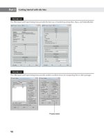
The Batch Render window, shown in Figure 47.1, is accessed from the Rendering menu. Render tasks can
be added to the list by clicking the Add button. Render tasks can be disabled by selecting the check box to
the left of the task name.
FIGURE 47.1
The Batch Render window lets you define render tasks to be run as a batch process.
For each task, you can set the task’s Name, Output Path, Camera, and render Preset. The Scene State drop-
down list lets you select any scene states that are defined using the Tools ➪ Manage Scene States command.
Each new task added to the Batch Render window uses the default render parameters for its frame range,
dimensions, and pixel aspect, but if you enable the Override Preset option, then you can customize each of
these parameters for the selected task.
The Batch Render queue can be rendered over the network by enabling the Net Render option at the bot-
tom of the Batch Render window.
Managing scene states
A single scene file may have many different settings that you’d like to try as different renderings. For exam-
ple, you can set up a scene with different light settings, with different camera properties, or with unique
materials. Scene states let you define different sets of properties that can be recalled prior to a batch render-
ing. Each of these scene states can be part of a single Max file.
When the Tools ➪ Manage Scene States menu command is selected, the Manage Scene States dialog box
appears, as shown in Figure 47.2, which lets you Save, Restore, Rename, and Delete the existing list of
scene states. Clicking the Save button opens the Save Scene State dialog box, also shown in Figure 47.2. In
the Save Scene State dialog box, you can enter the name for the scene state and select which group of set-
tings to use. The options include Light Properties, Light Transforms, Object Properties, Camera Transforms,
Camera Properties, Layer Properties, Layer Assignment, Materials, and Environment.
1120
Advanced Lighting and Rendering
Part XI
61_381304-ch47.qxp 7/7/08 2:19 PM Page 1120
FIGURE 47.2
The Manage Scene States and Save Scene State dialog boxes let you define which properties to save as a state that
can be recalled for a batch render task.
Creating a standalone executable
After a batch render queue is established, you can click the Export to .bat button to open the Batch Render
Export to Batch File dialog box, where you can save the batch file as a .bat file. This saved file can be exe-
cuted from the command line or by using an agent.
Understanding Network Rendering
When you use network rendering to render your animation, Max divides the work among several machines
connected via a network, with each machine rendering some of the frames. The increase in speed depends
on how many machines you can devote to rendering frames: Add just one computer, and you double the
rate at which you can render. Add seven or eight machines, and instead of missing that important deadline
by a week, you can get done early and take an extra day off.
Machines connected to handle network rendering are often referred to collectively as a rendering farm. The
basic process during a network rendering goes like this: One machine manages the entire process and dis-
tributes the work among all the computers in the farm. Each machine signals the managing computer when
it is ready to work on another frame. The manager then sends or “farms out” a new frame, which gets
worked on by a computer in the rendering farm, and the finished frame gets saved in whatever format
you’ve chosen.
The software in Max that makes network rendering possible is called Backburner. You may have noticed
that it was installed when Max was installed. Max has several features to make the network rendering
process easier. If one of the computers in your rendering farm crashes or loses its connection with the man-
ager, the manager reclaims the frame that was assigned to the down computer and farms it out to a different
machine. You can monitor the status of any rendering job you have running, and you can even have Max
e-mail you when a job is complete.
One additional caveat to using network rendering is that you have no guarantee that the
frames of your animation will be rendered in order. Each participating computer renders
frames as quickly as possible and saves them as separate files, so you cannot use network rendering to create
.avi or .mov files. Instead, you have to render the scene with each frame saved as a separate bitmap file, and
then use the RAM Player, Video Post, or a third-party program (such as Adobe Premiere) to combine them
into an animation file format such as .avi.
NOTE
NOTE
1121
Batch and Network Rendering
47
61_381304-ch47.qxp 7/7/08 2:19 PM Page 1121
A licensed version of Max is required to do network rendering, but the good news is that only
one machine in your farm needs to have an
authorized
copy of Max installed. No authoriza-
tion whatsoever is needed on machines used for network rendering only. Simply install Max, and each net-
work rendering machine gets its authorization from the computer that launched the render job.
Setting up a Network Rendering System
Before getting into the details of setting up Max for network rendering, it’s important to understand the dif-
ferent parts of the network rendering system. This list shows the major players involved:
Manager: The manager is a program (manager.exe) that acts as the network manager. It’s the net-
work manager’s job to coordinate the efforts of all the other computers in your rendering farm.
Only one machine on your network needs to be running the manager, and that same machine can
also be used to render.
Server: A rendering server is any computer on your network used to render frames of your ani-
mation. When you run the server program (server.exe), it contacts the network manager and
informs it that this particular computer is available to render. The server starts up Max when the
manager sends a frame to be rendered.
3ds Max: At least one computer in your rendering farm must have an authorized copy of Max
running, although it does not need to be the same computer that is running the manager. It is
from this machine that you initiate a rendering job.
Monitor: The Monitor (monitor.exe) is a special program that lets you monitor your rendering
farm. You can use it to check the current state of jobs that are running or that have been queued.
You can also use it to schedule network rendering times. The Monitor is completely independent
from the actual rendering process, so you can use it on one of the machines in your rendering
farm, or you can use it to remotely check the status of things by connecting over the network.
Starting the Network Rendering System
Now that you know all the pieces involved, you’ll need to setup your network and install a copy of Max on
all the network machines that you plan on using. When installing Max on a network machine, you can use
the Compact option so that Max installs only the minimum number of files it needs to be able to render.
You also need to choose a destination directory where you want Max to be installed. If possible, just accept
the displayed default destination and click Next.
Installing 3ds Max in the same directory on every computer can save you some maintenance
headaches later on. Managing bitmap and plug-in directories is much easier if each machine
has the same directory layout.
You also need to setup several shared directories on the network where the scenes and materials can be
accessed from and where the rendered scenes can be saved. Once you have these shared folders in place,
you are ready to start up your network rendering system.
TIP
TIP
NOTE
NOTE
1122
Advanced Lighting and Rendering
Part XI
61_381304-ch47.qxp 7/7/08 2:19 PM Page 1122
Tutorial: Initializing the network rendering system
The very first time you start your rendering farm, you need to help Max do a little initialization.
To initialize the network rendering system, follow these steps:
1. Start the network manager on one machine in your rendering farm. This program, Manager.exe, is
in the Backburner directory. You can start the manager by selecting it and pressing Enter in
Windows Explorer. After it starts up, you first see the Backburner Manager General Properties
dialog box. This dialog box appears only the first time you run the Manager.exe program or if you
choose Edit ➪ General Settings. I cover its settings later in the chapter. After setting these proper-
ties, click OK, and the Manager window, shown in Figure 47.3, runs.
FIGURE 47.3
Starting the network manager
2. Now start a network server on each computer that you plan to use for rendering. To do this, find
and start the Server.exe program just like you did with Manager.exe. When you start this program
for the first time, the Backburner Server General Properties dialog box appears. This dialog box is
covered later in the chapter. Click OK, and the Network Server window appears, as shown in
Figure 47.4.
FIGURE 47.4
Starting a network server. Notice that the server is already looking for the manager.
When the server finds the manager, it displays a message that the registration is accepted. The Network
Manager window also shows a similar message.
If the server had trouble connecting to the manager, you need to follow these two additional steps:
1. If automatic detection of the manager fails, the server keeps trying until it times out. If it times
out, or if you just get tired of waiting, choose Edit ➪ General Settings to open the Backburner
Server General Properties dialog box, shown in Figure 47.5. In this dialog box, uncheck the
1123
Batch and Network Rendering
47
61_381304-ch47.qxp 7/7/08 2:19 PM Page 1123
Automatic Search box and type in the name or IP address of the computer that is running the net-
work manager. In this case, the server tried but couldn’t quite find the manager, so it had to be
told that the manager was running on the computer whose IP address is 150.150.150.150.
FIGURE 47.5
Manually choosing the manager’s IP address
2. Click OK to close the Backburner Server General Properties dialog box, and then click Close to
shut down the server (doing so forces the server to save the changes you’ve made). Restart the
server the same way you did before, and now the server and manager are able to find each other.
The network manager does not need to have a computer all to itself, so you can also run a net-
work server on the same computer and use it to participate in the rendering.
Tutorial: Completing your first network rendering job
Your rendering farm is up and running and just dying to render something, so let’s put those machines to work.
To start a network rendering job, follow these steps:
1. Start Max, and create a simple animation scene. This should be as simple as possible because all
you’re doing here is verifying that the rendering farm is functional.
2. In Max, choose Rendering ➪ Render (F10) to bring up the Render Setup dialog box. In the Time
Output section of this dialog box, be sure that Range is selected so that you really do render mul-
tiple frames instead of the default single frame.
3. In the Render Output section of the Render Scene dialog box, click Files to open the Render
Output File dialog box. In the Save In section, choose the output drive that can be accessed over
the network and directory that you created in the “Configuring shared directories” section.
4. In the File name section of the Render Output File dialog box, type the name of the first frame.
Max automatically numbers each frame for you. Choose a bitmap format from the Save as type list
(remember, an animation format will not work).
5. Click Save to close the Render Output File dialog box. (Some file formats might ask you for addi-
tional information for your files; if so, just click OK to accept the default options.) Back in the
Render Scene dialog box, Max displays the full path to the output directory.
6. In the Render Output section of the Render Scene dialog box, check the Net Render option, as
shown in Figure 47.6. Change any other settings you want, such as selecting a viewport, and then
click Render.
NOTE
NOTE
1124
Advanced Lighting and Rendering
Part XI
61_381304-ch47.qxp 7/7/08 2:19 PM Page 1124
FIGURE 47.6
The Net Render option must be enabled to start a network rendering job.
A Network Job Assignment dialog box opens, like the one shown in Figure 47.7.
FIGURE 47.7
Use the Network Job Assignment dialog box to locate the manager to handle the rendering job.
1125
Batch and Network Rendering
47
61_381304-ch47.qxp 7/7/08 2:19 PM Page 1125
7. In the Enter Subnet section of the Network Job Assignment dialog box, click Connect if the
Automatic Search box is checked. If it isn’t checked, or if your servers had trouble finding the
manager in the “Initializing the network rendering system” tutorial earlier in this chapter, type the
IP address of the machine running the manager and then click Connect.
8. Max then searches for any available rendering servers, connects with it, and adds its name to the
list of available servers. Click the server name once, and click Submit.
If you try to submit the same job again (after either a failed or a successful attempt at render-
ing), Max complains because that job already exists in the job queue. You can remove the job
using the Monitor, or you can click the + button on the Network Job Assignment dialog box, and Max adds a
number to the job name to make it unique.
After you’ve submitted your job, notices appear on the manager and the servers (like the ones shown in
Figures 47.8 and 47.9) that the job has been received. Soon Max starts up on each server, and you see a
Rendering dialog box showing the progress of the rendering task. As you can see, this displays useful infor-
mation such as what frame is being rendered and how long the job is taking. When the entire animation has
been rendered, you can go to your output directory to get the bitmap files that Max generated. The render
servers and the render manager keep running, ready for the next job request to come in.
FIGURE 47.8
The network manager detects the new job.
FIGURE 47.9
One of the network servers receives the command to start a new job.
Job assignment options
The Network Job Assignment dialog box, shown previously in Figure 47.7, has an important section that
you didn’t use for your first simple render job; it’s called Options.
The Options section has the following settings:
Enabled Notifications: Lets you tell Max when to notify you that certain events have occurred. If
you check the Enable Notifications option, the Define button becomes active. The Define button
opens a Notifications dialog box, shown in Figure 47.10.
TIP
TIP
1126
Advanced Lighting and Rendering
Part XI
61_381304-ch47.qxp 7/7/08 2:19 PM Page 1126
FIGURE 47.10
The Notifications dialog box lets you specify which type of notifications to receive.
Split Scan Lines: This option breaks a rendered image into strips that can be rendered separately.
The Define button lets you specify the Strip Height, Number of Strips, and any Overlap.
Ignore Scene Path: Use this option to force the servers to retrieve the scene file via TCP/IP. If dis-
abled, the manager copies the scene file to the server.
Rendered Frame Window: Use this option if you want to be able to see the image on the server
as it gets rendered.
Include Maps: Checking this box makes Max compress everything that it needs to render the
scene (including the maps) into a single file and send it to each server. This option is useful if
you’re setting up a rendering farm over the Internet, although it takes more time and network
bandwidth to send all that extra information.
Initially Suspended: This option pauses the rendering before it starts so that you can manually
start it when the network is ready.
Use Selected/Use Group/Use All Servers: The Server Usage option makes the selected server, a
group of servers, or all servers listed in the Server panel fair game for rendering.
Use Alternate Path File: This option lets you specify an alternate path for map and other files,
which is entered in the text field below the check box.
Configuring the Network Manager and Servers
You can configure both the manager and servers using their respective General Properties dialog boxes. You
open these dialog boxes by choosing Edit ➪ General Settings.
The network manager settings
The rendering manager has some options that let you modify how it behaves. You specify these options in
the Network Manager General Properties dialog box, shown in Figure 47.11. To open this dialog box, select
Edit ➪ General Settings in the Manager window.
1127
Batch and Network Rendering
47
61_381304-ch47.qxp 7/7/08 2:19 PM Page 1127
FIGURE 47.11
The Backburner Manager General Properties dialog box
This dialog box includes the following sections:
TCP/IP: Here you can change the communications ports used by the manager and the servers. In
general, leaving these alone is a good idea. If some other program is using one of these ports,
however, Max won’t be able to render via the network, so you need to change them. If you change
the Server Port number, be sure to change it to the same number on all your rendering servers. If
you change the Manager Port number, you also need to change two files on your hard drive to
match: queueman.ini (in your 3dsmax directory) and client.ini (in your 3dsmax\network direc-
tory). Both have lines for the Manager Port, and you can edit these files with any text editor or
word processor.
General: The Max Concurrent Assignments field is used to specify how many jobs the rendering
manager sends out at a time. If you make this number too high, the manager might send out jobs
faster than the servers can handle them. The default value here is fine for most cases.
The network manager can automatically attempt to restart servers that failed, giving your ren-
dering farm much more stability.
Failed Servers: Usually, Max doesn’t send more frames to a server that previously failed. If you
check the Restarts Failed Servers box, Max tries to give the server another chance. The Number of
Retries field tells Max how many times it should try to restart a server before giving up on the par-
ticular server for good, and the Minutes Between Retries field tells Max the number of minutes it
should wait before trying to give the failing server another job.
The rendering manager writes the configuration settings to a file on the disk that gets read
when the manager loads. If you make changes to any of the settings, shutting down the man-
ager and starting it up again to guarantee that the changes take effect is best.
NOTE
NOTE
NOTE
NOTE
1128
Advanced Lighting and Rendering
Part XI
61_381304-ch47.qxp 7/7/08 2:19 PM Page 1128
Direct Access to Jobs Path: This setting lets you specify a different path that exists anywhere on
the network, regardless of where the manager is running. Separate fields are available for Win32
paths and Unix paths. If the Use Jobs Path option is selected, then the specified path is used.
Default Job Handling: This section lets you tell the Manager what to do after the rendering job is
finished. The options include Do Nothing, Delete or Archive, and Delete or Archive after a speci-
fied number of days. This option gives you a way to clean out your queue.
The network servers settings
As you may have guessed, the Properties button on the Network Server window serves a similar purpose as
the one on the Network Manager window: It enables you to specify the behavior of the network server.
Clicking this button displays the Backburner Server General Properties dialog box.
This dialog box has the following section:
TCP/IP: The port numbers serve the same function as they do for the rendering manager,
described in the previous section. If you change them in the manager properties, change them
here. If you change them here, change them in the manager properties.
The Manager Name or IP Address setting lets you override automatic detection of the render-
ing manager and specify its exact location on the network. Generally, letting Max attempt to
find the manager itself is best; if it fails, override the automatic detection by clearing the Automatic check
box. If you happen to be running multiple managers on the same network, the servers connect to the first
one they find. In this case, you have to manually choose the correct server.
Keep in mind that the server properties aren’t shared among your servers, so if you want something to
change on all your servers, you have to make that change on each machine.
As with the rendering manager settings, if you change anything in the Network Servers
Properties dialog box, be sure to shut down the server and restart it.
Logging Errors
Both the Network Manager and Network Server windows have a Logging button that you can click to
access the Logging Properties dialog box, where you can configure how log information gets handled. This
dialog box, shown in Figure 47.12, looks the same for managers and servers. You can access this dialog box
with the Edit ➪ Log Settings command.
Max generates the following types of messages:
Error: Anything that goes wrong and is serious enough to halt the rendering of a frame.
Warning: A problem that Max can still work around. If a server fails, for example, a warning is
generated, but Max continues the rendering job by using other servers.
Info: A general information message, such as notification that a job has arrived or that a frame is
complete.
Debug: A lower-level message that provides information to help debug problems with the render-
ing farm.
Debug Extended: The same as the Debug option with more details.
NOTE
NOTE
NOTE
NOTE
1129
Batch and Network Rendering
47
61_381304-ch47.qxp 7/7/08 2:19 PM Page 1129
FIGURE 47.12
The logging options for managers and servers let you tell Max where to report what.
Max displays the type of message and the message itself in two locations: in the list window and in a log file
(in your 3dsmax\network directory). The Logging Properties dialog box lets you choose whether each type
of message gets reported to the screen, the log file, both places, or neither place. You can also use the Clear
buttons to get rid of old messages.
Using the Monitor
The Monitor is a powerful utility that helps you manage your rendering farm and all the jobs in it. If you
use network rendering frequently, then the Monitor quickly becomes your best friend. You start it the same
way that you start a rendering server or manager: Go to the 3dsmax directory, find QueueManager.exe, and
double-click it. Every computer that has Max installed on it also has a copy of the Monitor, so you can use it
from any machine on your network. The main screen is shown in Figure 47.13.
When the Monitor starts up, it automatically searches for the rendering manager and connects to it. (If you
have more than one manager running, you have to choose which one to connect to.)
The main screen is divided into three panes. The top-left pane shows the job queue, and their Priority and
Status, and the top-right pane shows information about whatever you have selected in the left pane. You
can use the tabs at the top of this pane to select the information that you want to view. The information tabs
include Job Summary, Frames Summary, Advanced (which shows the rendering parameters), Render
Elements, and Log.
The bottom pane lists all the available servers. Next to each server in the left pane is an icon that reflects its
current status. Green icons mean that the job or server is active and hard at work. Yellow means the server
is idle. Red means that something has gone wrong, and gray means that a job has been inactivated or that a
server is assigned to a job but is absent. When a job is complete, it can be deleted from the queue.
1130
Advanced Lighting and Rendering
Part XI
61_381304-ch47.qxp 7/7/08 2:19 PM Page 1130
FIGURE 47.13
The Monitor makes managing a rendering farm quick and easy.
Jobs
If you choose a job in the top-left pane, the top-right pane displays information about the selected job. The
panels in the top-right pane are as follows:
Job Summary: Lists some of the rendering options you chose before you submitted the job.
Among other things, the example in the figure shows that the job was rendered to 640 × 480
pixels.
Frames Summary: Lists the details of rendering each frame in the animation, including the time
required to render and the server used.
Advanced: Lists advanced settings from the Render Scene dialog box and gives limited informa-
tion about the scene itself.
Render Elements: Lists the details of each render element included as part of the job.
Log: Displays important messages from the job log. Whereas the log file on each server lists
events for a particular server, this pane lets you see all the messages relating to a particular job.
When you point at a job in the top-left pane and right-click, a small pop-up menu appears. On this menu,
you can delete a job from the queue or you can choose to activate or deactivate it. If you deactivate a job, all
the servers working on that job save their work in progress to disk and then move on to the next job in the
queue. This feature is very useful when you have a lower-priority job that you run when no other jobs are
waiting; when something more important comes along, you deactivate the job so that you can later activate
it when the servers are free again.
One last useful feature for jobs is that you can reorder them by dragging a job above or below other jobs.
Jobs higher on the screen are rendered before lower ones, which enables you to “bump up” the priority of a
particular job without having to deactivate other ones.
A file with a Critical priority is rendered immediately.
NOTE
NOTE
1131
Batch and Network Rendering
47
61_381304-ch47.qxp 7/7/08 2:19 PM Page 1131
Servers
If you right-click a server and select Properties from the pop-up menu, the Server Properties dialog box,
shown in Figure 47.14, opens. This dialog box contains information about the selected server.
FIGURE 47.14
The Server Properties dialog box displays information about the server.
Many other features are available in the right-click pop-up menu. Using this pop-up menu, you can assign
the server to a selected job, remove the server from its selected job, display specific server information, cre-
ate a server group, or view the Week Schedule, as shown in Figure 47.15. Using the Week Schedule dialog
box, you can set the active rendering period for a server.
FIGURE 47.15
The Week Schedule dialog box can set the time during the week when a server is available for rendering.
The Week Schedule dialog box lets you decide when a particular machine is available for rendering. (For
example, you can have your coworker’s computer automatically become available for rendering after he or
she goes home for the night.)
1132
Advanced Lighting and Rendering
Part XI
61_381304-ch47.qxp 7/7/08 2:19 PM Page 1132
Click and drag with your mouse over different hours to select a group of times. Alternatively, you can click
a day of the week to select the entire day or click a time to select that time for every day. In the example
shown in Figure 47.15, the server is scheduled to render in the evenings and on the weekends.
After you’ve selected a group of times, click Allow to make the server available for rendering during that
time or click Disallow to prevent rendering. When you’re finished, click OK to close the Server Properties
dialog box and return to the Monitor dialog box.
If you have several jobs going at once but suddenly need to get one finished quickly, you can take servers
off one job and put them on another. To remove a server, right-click its name in the left pane of the Monitor
dialog box and choose Delete Server (Ctrl+Enter) from the pop-up menu. The icon next to the server turns
black, indicating that it has been unassigned. To assign this server to another job, right-click the server
name in the list of servers for the job you want to assign it to, and choose Assign to Selected Jobs.
Summary
If your goal is to spend more time modeling and less time waiting for rendering jobs to complete, then the
network rendering services provided by 3ds Max can help you take a step in the right direction. After the
initial complexities of setting up a rendering farm are out of the way, network rendering can be a great asset
in helping you reach important deadlines, and it lets you enjoy your finished work sooner. Even if you
can afford to add only one or two computers to your current setup, you’ll see a tremendous increase in
productivity — an increase that you can’t truly appreciate until you’ve completed a job in a fraction of the
time it used to take!
In this chapter, you accomplished the following:
Used the Batch Render window to create a batch render queue
Used the rendering manager and servers to carry out rendering jobs
Used the Monitor to control job priority
Made Max notify you when problems occur or when jobs finish
Performed batch rendering even if you don’t have a network
In the next chapter, you’ll look at the compositing options including Video Post and the various render
elements that are available in Max.
1133
Batch and Network Rendering
47
61_381304-ch47.qxp 7/7/08 2:19 PM Page 1133
61_381304-ch47.qxp 7/7/08 2:19 PM Page 1134
A
fter you’ve completed your scene and rendered it, you’re finished, right?
Well, not exactly. You still have post-production to complete — that’s
where you work with the final rendered images to add some additional
effects. This phase of production typically takes place in another package, such as
Photoshop, Autodesk’s Combustion, or Adobe’s After Effects, and understanding
how to interact with these packages can be a lifesaver when your client wants
some last-minute changes (and they always do).
You can set Max to render any part in the rendering pipeline individually. These
settings are called render elements. By rendering out just the Specular layer or just
the shadow, you have more control over these elements in your compositor.
If you don’t have access to a compositing package or even if you do, Max
includes a simple interface that can be used to add some post-production effects.
This interface is the Video Post interface.
You can use the Video Post window to composite the final rendered image with
several other images and filters. These filters let you add lens effects like glows
and flares, and other effects like blur and fade, to the final output. The Video
Post window provides a post-processing environment within the Max interface.
Many of the post-processing effects, such as glows and blurs,
also are available as render effects, but the Video Post window
is capable of much more. Render effects are covered in Chapter 45, “Using
Atmospheric and Render Effects.”
NOTE
NOTE
1135
IN THIS CHAPTER
Learning about post-processing
Compositing with Photoshop,
Premiere, and After Effects
Introducing Combustion
Using render elements
Using the Video Post interface
Working with sequences
Understanding the various filter
types
Adding and editing events
Specifying event ranges
Using the Lens Effects filters
Compositing with Render
Elements and the Video Post
Interface
62_381304-ch48.qxp 7/7/08 2:19 PM Page 1135
Using External Compositing Packages
Before delving into the Video Post interface, let’s take a quick look at some of the available compositing
packages. Several of these packages have direct links into Max that can be used to give you a jump on the
post-production process.
Compositing with Photoshop
Perhaps the most common tool for compositing images is Photoshop. Photoshop can bring multiple images
together in a single file and position them relative to one another. Working with layers makes applying sim-
ple filters and effects to the various element pieces easy.
Figure 48.1 shows Photoshop with several separate pieces, each on a different layer.
FIGURE 48.1
Photoshop is an important compositing tool for static images.
To composite images in Photoshop, you need to load all the separate images into Photoshop and then select
the portions of the images that you want to combine. When saving image files in Max, be sure to include an
alpha channel. You can see the alpha channel in the Rendered Frame window if you click the Display Alpha
Channel button, as shown in Figure 48.2.
1136
Advanced Lighting and Rendering
Part XI
62_381304-ch48.qxp 7/7/08 2:19 PM Page 1136
FIGURE 48.2
The Rendered Frame window can display an image’s alpha channel.
In Photoshop, you can see an image’s alpha channel if you select the Channels panel in the Layers palette.
Selecting the alpha channel and using the Magic Wand tool makes selecting the rendered object easy. After
it’s selected, you can copy and paste the rendered image onto your background image as a new layer.
Not all image file formats support an alpha channel. When rendering images to be compos-
ited, but sure to use an alpha channel format such as RLA, RPF, PNG, or TGA.
After all your images have been positioned on the background image, you can apply a Filter, such as a
Gaussian Blur, to smooth the edges between the composite images.
Video editing with Premiere
Photoshop works with still images, but if you work with animations, then Adobe has Premiere to help with
your video editing needs. The editing that Premiere makes possible includes patching several animation
clips together, adding sound, color-correcting the frames, and adding transitions between animation clips.
Within Premiere, various animation clips can be imported (or dragged directly from Windows Explorer)
into the Project panel. From here, the clips can be dropped onto the Timeline in the desired order. The
Monitor panel shows the current animation or individual animation clips.
Sound clips can be dropped in the Timeline in the Audio track. The Title menu also can be used to add text
to the animation. Another common activity in Premiere is to add transition effects between clips. This is
done by clicking the Effects tab in the Project panel, selecting a transition effect, dragging the effect to the
Timeline, and dropping it between two animation clips.
When the entire sequence is completed, you can render it using the Sequence ➪ Render Work Area menu
command. The completed animation file then can be saved using the File ➪ Export menu command.
NOTE
NOTE
1137
Compositing with Render Elements and the Video Post Interface
48
62_381304-ch48.qxp 7/7/08 2:19 PM Page 1137
Tutorial: Creating a montage of Space Warp animations
In this example, you combine several animations into a single animation sequence.
To create a montage of several animations using Premiere, follow these steps:
1. Open Premiere, and drag the Space Warp animations from the Chap 48 directory on the DVD to
the Project panel. This file was saved using an older version of Premiere.
2. Select all five animation clips, and drag them to the Video 1 row in the Timeline panel. Select
Sequence ➪Zoom In four times to space the animations out in the Timeline panel so they are visible.
3. If you want to change the order of the animation clips, just drag them to the desired position in
the Timeline panel. Make sure that they run consecutively.
4. Click the Effects tab in the Project panel, and open the Video Transitions folder. Select one of the
transition effects, and drag it from the Project panel to the Timeline panel. You can drop a differ-
ent effect where each animation clip meets its neighbor.
5. Click the Play button in the Monitor panel to see the resulting animation sequence. If you’re com-
fortable with it, select Sequence ➪ Render Work Area to render the final sequence.
6. When the rendering completes, save the animation using the File ➪ Export➪Movie menu command.
Figure 48.3 shows the Premiere interface with the animation clips loaded and positioned in the Timeline
panel.
FIGURE 48.3
Premiere can be used to combine several animation sequences together.
1138
Advanced Lighting and Rendering
Part XI
62_381304-ch48.qxp 7/7/08 2:19 PM Page 1138
Video compositing with After Effects
If you need to add a little more to your animations than just transitions, you should look into Adobe’s After
Effects. After Effects lets you composite 2D and 3D clips into a single image or animation. You can paint
directly on the animation frames, add lights and cameras, and create visual effects such as Distort, Shatter,
and Warp.
After Effects includes a library of resources much like those found in Premiere. These resources can be posi-
tioned on a Composition pane. Effects applied to the loaded animation clip are listed in the Effects panel
along with all the effects settings.
After Effects includes many of the same tools used in Photoshop and Illustrator. These tools let you paint
and select portions of the animation clip as if it were a still image, but the results can be added or removed
over time.
Tutorial: Adding animation effects using After Effects
Some effects are much easier to add using a package like After Effects than to create in Max. A good exam-
ple is adding a blurry look and the waves coming from a heat source to the melting snowman animation
created in Chapter 21.
To add video effects using After Effects, follow these steps:
1. Open After Effects and drag the Melting snowman.avi file from the Chap 48 directory to the
Project panel.
2. Select Composition ➪ New Composition, select the NTSC, 640 × 480 option from the Preset list,
and click OK.
3. Drag the Melting snowman.avi file from the Project panel, and drop it on the Composition pane.
4. With the animation selected in the Composition pane, select Effect ➪ Distort ➪ Wave Warp. The
Wave Warp effect appears in a panel. Set the Wave Height to 4, the Wave Width to 30, the
Direction to Vertical, and the Wave Speed to 1. This adds a heat wave effect to the entire animation.
5. Select Effect ➪ Blur & Sharpen ➪ Gaussian Blur, and set the Blurriness value to 3.0.
6. In the Timeline panel, drag the Work Area End icon so that it coincides with the end of the
animation.
7. Select Composition ➪ Make Movie. In the Render Queue dialog box that opens, click the Render
button to render the animation with its effects.
Figure 48.4 shows the After Effects interface with the animation clip loaded.
Introducing Combustion
Autodesk offers an end-to-end solution for production houses to complete their work; on the receiving end
of Max is a product called Combustion. Combustion is a different animal from Max, but its array of
weapons is just as deadly in a slightly different arena. The biggest difference between Combustion and
Photoshop is that Combustion can handle animations and Photoshop can work only with static images.
1139
Compositing with Render Elements and the Video Post Interface
48
62_381304-ch48.qxp 7/7/08 2:19 PM Page 1139
FIGURE 48.4
After Effects can add special effects to an animation sequence.
Combustion enables motion graphics, compositing, and visual effects, which doesn’t sound too different
from what Max does, except for that funny word — compositing. If you think of the final rendered image
produced using Max as just an image that needs to be combined with other elements such as text, logos,
other images, or even a DVD menu, then you’re starting to see what post-production teams know.
Compositing is the process of combining several different elements into a finished product. Positioning
these elements can even be done in 3D by placing images behind or in front of other images or in time by
working with animations.
But wait, you say: this is a book about Max, not about Combustion. Yes, but Combustion is integrated with
Max very nicely, and that is what I want to show. Several key integration points include Combustion maps
and Render Elements.
Using Combustion maps
If you apply a Combustion type map to the Diffuse map channel of a material, then the Combustion
Parameters rollout, shown in Figure 48.5, appears. Clicking the Edit button in the rollout actually opens
Combustion and lets you create a new workspace.
1140
Advanced Lighting and Rendering
Part XI
62_381304-ch48.qxp 7/7/08 2:19 PM Page 1140