autocad 2007 and autocad lt 2007 bible - phần 4 docx
Bạn đang xem bản rút gọn của tài liệu. Xem và tải ngay bản đầy đủ của tài liệu tại đây (2.2 MB, 130 trang )
348
Part II ✦ Drawing in Two Dimensions
use any of the techniques for editing text that I discuss in the “Editing paragraph text” section
earlier in this chapter. You can change the properties of the text so that they don’t match the
table style. For example, you can change the height or font of the text.
Changing table properties
You can also change properties of the actual table. If you double-click the table itself — that
is, any of the grid lines — the Properties palette opens. Here, you can modify any conceivable
table property, including its layer, its color, the number of rows or columns, or any of its style
properties. If you want to revert to old-fashioned lines, you can explode the table. Of course,
you can no longer edit the table as a table anymore; you just have lines and text.
To select the entire table, click any gridline of the table. You see grips at the corners of the
table and at several other cell junctions. If you select the table and right-click, then you can
use the shortcut menu to make additional changes to the table. For example, you can size
columns or rows equally or remove property overrides. If you make a change to a cell, such
as the cell’s alignment or color, you can use the Remove All Property Overrides item on the
shortcut menu to change the cell’s properties back to match the rest of the table.
To select a cell, click inside that cell. You can then right-click and use the shortcut menu,
which has the following items:
✦ Cell Alignment: Changes the alignment of the text in the cell, using the standard text-
alignment options available for multiline text.
✦ Cell Borders: Opens the Cell Border Properties dialog box, where you can specify bor-
der properties for that individual cell.
✦ Format: Opens the Table Cell Format dialog box, where you can change the data type
and format.
✦ Match Cell: Matches cell properties. At the
Select destination cell: prompt on the
command line, pick another cell that you want to have the same properties. The
prompt repeats until you press Enter.
✦ Insert Block: Opens the Insert a Block in a Table Cell dialog box, where you can select
the block that you want to insert, specify the block’s alignment in the cell, and set its
scale and rotation angle. If you select the Autofit check box, the block is automatically
scaled to fit the table cell.
✦ Insert/Edit Field: Lets you insert or edit a field. I discuss fields in the next section of
this chapter.
✦ Insert Formula: Lets you insert a formula, as previously explained.
✦ Edit Cell Text: Opens the In-Place Text Editor so that you can edit text.
✦ Insert Columns: Inserts a column. You can choose to insert the column to the right or
to the left of the current cell’s column.
✦ Delete Columns: Deletes the column that the current cell is in.
✦ Size Columns Equally: Makes two or more columns that you select equally wide.
✦ Insert Rows: Inserts a row. You can choose to insert the row above or below the cur-
rent cell’s row.
20_788864 ch13.qxp 5/22/06 7:16 PM Page 348
349
Chapter 13 ✦ Creating Text
✦ Delete Rows: Deletes the row that the current cell is in.
✦ Size Rows Equally: Makes all of your rows an equal height.
✦ Remove All Property Overrides: Removes any formatting that you applied to the
selected cell.
✦ Delete Cell Contents: Deletes any text or block in the current cell.
✦ Merge Cells: Merges two or more cells together. You can choose to merge all of the
selected cells into one cell, to merge them by row, or to merge them by column.
✦ Unmerge Cells: Unmerges merged cells and recreates all of the original cells.
✦ Properties: Opens the Properties palette so that you can change the cell’s properties.
When you edit a table, column and row headers appear so that you can easily refer to cells in
your formulas. You can change the background color of these headers to make the text
clearer. Select a table, right-click and choose Table Color Indicator. You can then choose a
color in the Select Color dialog box.
You can select multiple cells and apply changes to those cells. To select multiple cells, use
one of the following techniques:
✦ Click inside one cell and drag over the other cells that you want to select. Release the
mouse button at the last cell.
✦ Click inside one cell, hold down Shift, and click inside the last cell that you want to select.
To enter the same text in multiple cells, select the cells. Then open the Properties palette and
enter the text in the Contents item. The text appears in all of the selected cells.
When you select multiple cells, you can also merge the cells. Right-click and choose Merge Cells
from the shortcut menu. By merging cells, you can create fairly complex table structures.
You can also edit tables using grips. To understand editing tables with grips, imagine that the
left side of the table is the stable side, while the right side of the table is the flexible side. The
top-left grip is the base point for the entire table. You can do the following edits with grips:
✦ Upper-left grip: Moves the entire table.
✦ Upper-right grip: Stretches the table horizontally. As you change the width of the table,
the columns also stretch proportionally.
✦ Lower-left grip: Stretches the table vertically. As you change the height of the table,
the rows also stretch proportionally.
✦ Lower-right grip: Stretches the table both vertically and horizontally. The columns and
rows adjust proportionally.
✦ Top-of-column grip: Adjusts the width of the column to the left of the grip. The entire
table adjusts accordingly. If you press Ctrl while moving a column grip, the adjacent
columns adjust, but the width of the table remains unchanged.
You can export a table to comma-delimited (
.csv) format. You can then open the table data
with a database or spreadsheet program. To export a table, follow these steps:
Tip
20_788864 ch13.qxp 5/22/06 7:16 PM Page 349
350
Part II ✦ Drawing in Two Dimensions
1. Select the table.
2. Right-click and choose Export.
3. In the Export Data dialog box, choose a name and location for the file.
4. Click Save.
The drawing used in the following exercise on creating tables, ab13-c.dwg, is in the
Results folder on the CD-ROM.
STEPS: Creating Tables
1. Open ab13-c.dwg from the CD-ROM. This is the same drawing used in the previous
exercise.
2. Save the file as
ab13-06.dwg in your AutoCAD Bible folder.
3. Choose Table from the Draw toolbar. (If the Draw toolbar is not displayed, right-
click any toolbar and choose Draw from the list of toolbars.) In the Insert Table
dialog box, click the Ellipsis button to the right of the Table Style Name drop-down list.
4. In the Table Style dialog box, click New. In the Create New Table Style dialog box, enter
AcreageSchedule in the New Style Name text box. The Start With text box should read
Standard. Click Continue. The New Table Style dialog box opens.
5. From the Text Style drop-down list, choose
ROMANS. In the Text Height text box, enter
12.5. Because you want the numbers in the table to be right-aligned, choose Middle
Right from the Alignment drop-down list. In the Cell Margins section, change both the
Horizontal and Vertical text box values to 5.
6. Click the Column Heads tab. Make sure that the Include Header Row check box is
checked. Again, set the Text Style to
ROMANS and the Text Height to 12.5. Leave the
alignment as Middle Center.
7. Click the Title tab. Make sure that the Include Title Row check box is checked. Make
the following changes:
• Text Style:
ROMANT (for a different look).
• Text Height: 13.5 to make the title text bigger than the rest of the table text.
• Text Color: Click the Text Color drop-down list and choose Select Color. From the
Select Color dialog box, choose the lightest gray color (254) on the Index Color
tab. Click OK to return to the New Table Style dialog box.
• Fill Color: Click the Fill Color drop-down list and choose Blue.
• Grid Color: In the Border Properties section, click the Grid Color drop-down list
and choose Blue to match the fill. Click the All Borders button.
8. Click OK to return to the Table Style dialog box and click Set Current. Then click Close
to return to the Insert Table dialog box.
9. In the Insertion Behavior section of the dialog box, make sure that the insertion behav-
ior is set to
Specify insertion point. In the Columns & Row Settings section, set the
number of columns to 2 and the column width to 100. Set the number of data rows to 5.
The row height should be 1. Then click OK.
On the
CD-ROM
20_788864 ch13.qxp 5/22/06 7:16 PM Page 350
351
Chapter 13 ✦ Creating Text
10. In your drawing, pick an insertion point anywhere in the lower-right area of the draw-
ing. The In-Place Text Editor opens. Because you need to zoom in first, click anywhere
outside the editor and do a ZOOM Window around the table. Then double-click the
table to open the In-Place Text Editor again with the cursor in the title cell.
To zoom in without exiting the In-Place Text Editor, you can use the wheel of your mouse (if
you have one). I explain how to zoom using the mouse wheel in “The ZOOM Command” in
Chapter 8.
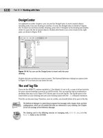
11. Complete the data for the four plats as shown in Figure 13-23, pressing Tab to go from
cell to cell.
12. Type Total in the last row. Right-click the cell and choose Justification➪ Middle Left
from the shortcut menu.
13. Click anywhere outside the In-Place Text Editor and then click the lower-right cell to
select it. Right-click the cell and choose Insert Formula ➪ Sum from the shortcut menu.
14. At the
Select first corner of table cell range: prompt, click anywhere inside cell
B3. At the
Select second corner of table cell range: prompt, click anywhere
inside cell B6. Press Enter. Your table should look like Figure 13-23.
Figure 13-23: The plat acreage table.
15. Save your drawing.
Inserting Fields
Most drawings contain information about the drawing, such as the last date it was revised,
the person who saved the drawing, or the sheet number in a sheet set. Draft plots often con-
tain additional information such as the time and drawing name. You may also want to insert
information about drawing objects, such as the area or circumference of a circle. Fields store
information and allow you to insert it into a drawing. You can also place fields in block
attributes, which I discuss in Chapter 18. When your drawing changes, you can update the
fields to keep them current.
Fields are not available in AutoCAD LT. If you open an AutoCAD drawing with fields in
AutoCAD LT, the fields display and update properly, unless you have changed the value of the
FIELDEVAL system variable to disable updating in certain situations.
You can insert fields anywhere that you might normally use text. As you start using fields,
you’ll think of many uses for them. You can format the text of a field in the same way that you
format any multiline text.
Tip
20_788864 ch13.qxp 5/22/06 7:16 PM Page 351
352
Part II ✦ Drawing in Two Dimensions
Sfld creates custom fields. Look in \Software\Chapter 13\sfld.
Creating fields
To create a new field as a multiline text object, you can use two methods:
✦ Choose Insert ➪ Field (the FIELD command).
✦ Open the In-Place Text Editor or any other text box where you can enter text, right-click
in the editor or text box, and choose Insert ➪ Field from the shortcut menu.
Whichever method you use, the Field dialog box opens, as shown in Figure 13-24.
Figure 13-24: Use the Field dialog box to choose,
format, and insert a field into your drawing. Here you
see the options for the
Date field.
The Field dialog box offers a huge variety of fields. To give you an idea of the possibilities,
here are the available categories of fields:
Date & Time: Offers various formats for inserting dates and times.
Document: Relates to data that you complete in the Properties dialog box. (Choose File ➪
Drawing Properties.)
Linked: Creates a field from a hyperlink.
Objects: Offers properties relating to block attributes (that you insert from the Block Editor),
formulas in tables, named objects (such as named views, layers, blocks, and so on), and
objects (any object that you select).
On the
CD-ROM
20_788864 ch13.qxp 5/22/06 7:16 PM Page 352
353
Chapter 13 ✦ Creating Text
Other: Displays values of AutoLISP variables and system variables.
Plot: Displays plot-related information such as scale, sheet size, and orientation.
SheetSet: Displays values relating to sheet sets.
Note that there are two date-related fields. The
CreateDate field creates a date based on the
current date. This field does not change if you open the drawing on a future date. For exam-
ple, you can use this field to show the last time a drawing was updated. The
Date field always
shows the current date.
To insert a field, follow these steps:
1. Choose a field category from the Field Category drop-down list. You can use the All cat-
egory to display all of the fields. The other categories help you to filter the fields, so
that you can more easily find the field that you want.
2. From the Field Names list, choose the field that you want to use.
3. Depending on the field that you choose, you can usually select a format or example for
the field. For example, you can choose a date format (such as m/d/yyyy) or a text for-
mat (such as title case).
4. Click OK.
• If you opened the Field dialog box by choosing Insert ➪ Field, the MTEXT com-
mand starts, and you see the
Specify start point or [Height/Justify]:
prompt. Pick a start point or use one of the options.
• If you started the MTEXT command first, the value of the field appears in the In-
Place Text Editor. Click OK on the editor’s main toolbar to place the text.
By default, fields appear in your drawing with a gray background. This background doesn’t
plot. If you want, you can remove the background by choosing Tools➪ Options and clicking
the User Preferences tab. In the Fields section, uncheck the Display Background of Fields
check box. Click OK to close the Options dialog box.
I cover the Properties dialog box and sheet sets in Chapter 26. For more information about
hyperlinks, see Chapter 28.
Figure 13-25 shows an example of a title block that uses fields.
Figure 13-25: Filling in a title block is easier when you use fields.
Cross-
Reference
20_788864 ch13.qxp 5/22/06 7:16 PM Page 353
354
Part II ✦ Drawing in Two Dimensions
Editing and updating fields
To edit a field, double-click the field’s text to open the In-Place Text Editor. Select the text,
right-click, and choose Edit field. The Field dialog box opens. You edit a field in the same way
that you define the field originally. When you’re done, click OK. The field is reevaluated imme-
diately. Close the In-Place Text Editor to place the edited field.
By default, a field is evaluated and updated, if necessary, whenever you open, save, plot,
eTransmit, or regenerate a drawing. (See Chapter 28 for information on eTransmitting a draw-
ing.) You can change when AutoCAD updates a field by choosing Tools➪ Options and clicking
the User Preferences tab. In the Fields section, click Field Update Settings. Check or uncheck
the items that you want, and then click Apply & Close. Click OK to close the Options dialog box.
You can manually update a field if you want. For example, you may have an object field that
displays the radius of a circle. If you resize the circle, you probably want to update the field.
To update a field, double-click the field to open the In-Place Text Editor. Select the text, right-
click, and choose Update Field. Close the In-Place Text Editor to return to your drawing.
Another method is to select the field and choose Tools➪ Update Fields. You can select as
many fields as you want.
To update all of the fields in a drawing, press Ctrl+A to select all of the objects in your draw-
ing and choose Tools➪ Update Fields.
You can convert a field to text. Double-click the field to open the In-Place Text Editor. Select
the text in the field, right-click and choose Convert Field to Text.
What happens to fields when you open a 2006 or 2007 drawing in a previous release of
AutoCAD? The fields display at their last value in the newer drawing but are not updated.
The drawing used in the following exercise on using fields, ab13-d.dwg, is in the Drawing
folder on the CD-ROM.
STEPS: Using Fields
1. Open ab13-d.dwg from your CD-ROM. Save the file as ab13-07.dwg in your AutoCAD
Bible folder. This drawing is zoomed in on the title block.
2. To set some of the drawing properties, choose File ➪ Drawing Properties. (I cover the
Properties dialog box in Chapter 26.) On the Summary tab, type the following in the
Title field: 6" thru 12" 2727 EPV Valves.
3. On the Custom tab, click Add. Enter the following two fields and values:
Drafter Enter your initials
Dwg No SK-1972
4. Click OK to return to your drawing.
5. Choose Multiline Text from the Draw toolbar. Pick two boundary points within the Title
box of the title block. The In-Place Text Editor opens. Right-click and choose Insert
Field to open the Field dialog box.
On the
CD-ROM
Tip
20_788864 ch13.qxp 5/22/06 7:16 PM Page 354
355
Chapter 13 ✦ Creating Text
6. From the Field Category drop-down list, choose Document. From the Field Names list,
choose Title. From the Format list, choose Title Case. Click OK. Click anywhere outside
the In-Place Text Editor to place the field.
7. Again choose Multiline Text from the Draw toolbar. Pick two boundary points within
the Dwg No box of the title block. In the In-Place Text Editor, right-click and choose
Insert Field to open the Field dialog box.
8. From the Field Names list, choose Dwg No. Click OK. Click anywhere outside the In-
Place Text Editor to place the field.
9. Again choose Multiline Text from the Draw toolbar. Pick two boundary points within
the Date box of the title block. In the In-Place Text Editor, right-click and choose Insert
Field.
10. From the Field Category drop-down list, choose Date & Time. From the Field Names list,
choose CreateDate. From the Format list, choose M/d/yy. Click OK. Click anywhere out-
side the In-Place Text Editor to place the field.
11. Save your drawing. The title block should look like Figure 13-26.
Figure 13-26: The title block after adding some fields.
Managing Text
Text is a complex object type that increases your drawing size and adds redraw and regenera-
tion time. The more-complex fonts, such as the TrueType fonts, can have a significant impact
on how long it takes to open and save a file. The techniques described in this section help
you to manage text and improve performance while editing your drawing.
Using Quicktext
The QTEXT command replaces all text with rectangles that approximate the placement of the
original text, as shown in Figure 13-27. All text objects, including dimensions, attributes, and
tolerances, are affected. To use QTEXT, type qtext ↵ on the command line. Type on ↵ to dis-
play the rectangles; type off ↵ to return to regular text. Then type regen ↵ at the command
line. Quicktext takes effect only after a regeneration; it does not apply to OLE objects that you
have pasted into a drawing from the Windows Clipboard (see Chapter 27).
20_788864 ch13.qxp 5/22/06 7:16 PM Page 355
356
Part II ✦ Drawing in Two Dimensions
Figure 13-27: A drawing with QTEXT on. Rectangles have
replaced all of the text.
Thanks to Rod Greer of R. G. Greer Design, Inc., Fergus, Ontario, for this drawing.
Using AutoCAD and AutoCAD LT fonts
AutoCAD and AutoCAD LT fonts are simpler than TrueType fonts, and AutoCAD fonts also
have a range of complexity. The simplest font is
txt.shx, which is the font used by the
default Standard text style. You can easily define a text style using an AutoCAD or AutoCAD
LT font and then change the font to something nicer just before plotting. Be aware that the
text may take up more or less space than before.
When your drawing cannot find the specified font, it uses an alternate font. This may happen
if you receive a drawing from someone else that uses a custom or third-party font that you
don’t have. You can specify the alternate font by choosing Tools➪ Options and clicking the
plus sign next to Text Editor, Dictionary, and Font File Names on the Files tab. Choose
Alternate Font File to specify the alternate font, which is
simplex.shx by default.
You can further control the fonts used in your drawing by customizing the Font Mapping File,
acad.fmp. The format is current_font; font_to_substitute. (You need to use the actual
filenames of the fonts.) To substitute a simpler font for the Arial Black font, you can add the
following line:
Ariblk.ttf;simplex.shx
To find the Windows TrueType fonts, look in the Fonts subfolder of your Windows folder.
To find acad.fmp, choose Tools ➪ Options and click the File tab. Double-click Text Editor,
Dictionary, and Font File Names. Double-click Font Mapping File. Click the path list to view
the location of acad.fmp. AutoCAD and AutoCAD LT only read the font-mapping file when
you open a new drawing, so that any changes that you make are effective only after you start
a new drawing.
Freezing text layers
Freezing text layers can reduce regeneration time dramatically; this is a good reason to give
text its own layer. Don’t forget to freeze dimension text, as well. Dimensions (see Chapter 14)
are usually placed on a separate layer.
Note
20_788864 ch13.qxp 5/22/06 7:16 PM Page 356
357
Chapter 13 ✦ Creating Text
Using MIRRTEXT
When you mirror sections of your drawing that include text, you usually don’t want any back-
ward text (unless you’re Alice going through the looking glass). The MIRRTEXT system vari-
able controls whether text is mirrored or retains its normal orientation. The default value for
MIRRTEXT is off, so that mirrored text is not backward. The text is copied to the mirrored
location, but reads from left to right (if that’s the direction of the language that you’re using).
If you do want to mirror the text, type mirrtext ↵. At the
New value for MIRRTEXT <0>:
prompt, type 1 ↵ to turn MIRRTEXT on. This system variable is saved with the drawing, and
so you may still need to change it when you open older drawings.
The drawing used in the following exercise on managing text, ab13-e.dwg, is in the
Drawings folder on the CD-ROM.
STEPS: Managing Text
1. Open ab13-e.dwg from your CD-ROM.
2. Save the file as
ab13-08.dwg in your AutoCAD Bible folder. This is a small section of
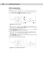
an electrical schematic, as shown in Figure 13-28. Make sure that ORTHO and OSNAP
are on, and set running snaps for endpoint, midpoint, and intersection.
Figure 13-28: A section of an electrical
schematic.
3. Type qtext ↵. At the
Enter mode [ON/OFF] <OFF>: prompt, type on_ ↵. Type regen ↵.
The command replaces the text with rectangles.
4. Type qtext ↵. At the
Enter mode [ON/OFF] <ON>: prompt, type off ↵. Type regen ↵.
Your original text reappears.
5. Start the MIRROR command. Follow the prompts:
Select objects: Start a window by picking 2 in Figure 13-21.
Specify opposite corner: Pick 1. Press Enter to end object
selection.
Specify first point of mirror line: Use the Midpoint running object
snap to pick the midpoint at 3.
51
3
2
On the
CD-ROM
20_788864 ch13.qxp 5/22/06 7:16 PM Page 357
358
Part II ✦ Drawing in Two Dimensions
Specify second point of mirror line: Pick any point vertical to the
first point.
Erase source objects? [Yes/No] <N>: ↵
The command mirrors the objects and the text, because the MIRRTEXT system variable
was set to 1. The text is backward.
6. Choose Undo from the Standard toolbar.
7. Type mirrtext ↵. At the
Enter new value for MIRRTEXT <1>: prompt, type 0 ↵.
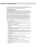
8. Repeat the mirror operation using the same instructions as in Step 5. This time the
command mirrors the objects, but the text reads properly, as shown in Figure 13-29.
Figure 13-29: The text on the right was
mirrored with MIRRTEXT set to 0.
9. Save your drawing.
Express Tools has a number of text routines that you may find very helpful. Table 13-3 lists
these tools.
Table 13-3: Express Tools for Text
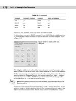
Command Menu Description
RTEXT Express
➪ Text ➪ Remote Text Displays text from an outside file. You can specify
the text style, height, and rotation. Use RTEDIT on
the command line to edit remote text.
TEXTFIT Express
➪ Text ➪ Text Fit Stretches or shrinks Text objects (but not MText)
to fit between two points.
TEXTMASK Express
➪ Text ➪ Text Mask Creates a wipeout, 3D face, or 2D solid object
behind the text, with a little extra space around
the text. You can use this to make text on top of a
hatch more legible.
TEXTUNMASK Express
➪ Text ➪ Text Unmask Removes a text mask.
20_788864 ch13.qxp 5/22/06 7:16 PM Page 358
359
Chapter 13 ✦ Creating Text
Command Menu Description
TXTEXP Express
➪ Text ➪ Explode Text Transforms Text or Mtext into geometrical shapes.
TXT2MTXT Express ➪ Text ➪ Convert Converts Text objects to Mtext objects.
Text to MText
ARCTEXT Express
➪ Text ➪ Arc-Aligned Text Aligns text along an arc.
TORIENT Express ➪ Text ➪ Rotate Text Rotates multiple text, Mtext, and attribute
definitions to a specified angle without moving
them, or aligns them so that they’re horizontal or
right-side up for easy reading.
TCIRCLE Express
➪ Text ➪ Enclose Text Encloses selected Text or Mtext inside a circle, a
with Object slot (a rectangle, but with arcs at each end), or a
rectangle.
TCOUNT Express
➪ Text ➪ Automatic Numbers lines of text by adding a prefix or suffix,
Text Numbering or by overwriting the text.
TCASE Express
➪ Text ➪ Change Offers the following ways to change the case of
Text Case text: uppercase, lowercase, sentence case, title
case, and toggle case.
Finding Text in Your Drawing
In a large, complex drawing with a lot of text, you may have difficulty finding specific text
that you need to edit. The FIND command lets you find and replace text anywhere in your
drawing — not only single-line text and multiline text but also text in tables, block attributes,
dimensions, hyperlink descriptions, and hyperlinks.
To use the FIND command, choose Edit➪ Find to open the Find and Replace dialog box, as
shown in Figure 13-30.
Figure 13-30: The Find and Replace
dialog box finds text anywhere in
your drawing.
20_788864 ch13.qxp 5/22/06 7:16 PM Page 359
360
Part II ✦ Drawing in Two Dimensions
Here’s how to use the Find and Replace dialog box:
1. Type the text that you want to find in the Find Text String text box. Use the drop-down
list to choose recently used text strings.
You can use wildcard characters such as * (for any number of characters), ? (for any single
character), and # (for any numeric character) in the Find Text String text box.
2. If you want to replace the text that you find with new text, type it in the Replace With
text box. This box also includes a drop-down list of recently used text strings.
3. If you want to limit or expand the scope of your search, use the Search in drop-down
box. If you selected objects before starting the FIND command, this drop-down list dis-
plays Current Selection. You can choose Entire Drawing from this list. You can also click
the Select Objects button to return to your drawing and select objects. The FIND com-
mand then limits its search to selected objects.
4. Choose Options to specify the type of text that FIND will search. By default, it searches
all types of text. The command can find text in fields, as well. You can also choose the
Match Case and Find Whole Words Only options.
5. Click Find or Find Next to find the next instance of the text string. The dialog box dis-
plays the text in the context of the text around it.
6. Click Replace to replace the text string with the replacement text. Click Replace All to
replace all instances of the text string with the replacement text.
7. If the Search In drop-down list is set to Current Selection, you can click Select All to
return to your drawing with all instances of the text string that you’ve searched for
selected. The prompt on the command line tells you how many objects it has selected.
For example, you can use this feature to delete all of these objects. Also, because the
objects have grips, it is easy to locate them in your drawing; this is useful when a draw-
ing is so large that you can’t read the text when you have the entire drawing displayed
on your screen.
8. Use the Zoom To button to zoom in to a selection that the FIND command has found.
You can then edit the text. As with the Select All button, this feature is useful for large
drawings where the text is not legible unless you zoom in.
9. After you’re finished, click Close to close the dialog box.
Checking Your Spelling
If you take pride in the accuracy of your drawings, you might as well make sure that the text
is spelled correctly. You can use the SPELL command to check your spelling. The spelling
checker acts just like the one in your word processor.
Choose Tools➪ Spelling and select some text objects to open the Check Spelling dialog box,
as shown in Figure 13-31. You can type all ↵ to check the spelling for the entire drawing.
Spell checking also checks text inside blocks. See Chapter 18 for a full explanation of blocks.
Note
Tip
20_788864 ch13.qxp 5/22/06 7:16 PM Page 360
362
Part II ✦ Drawing in Two Dimensions
Figure 13-32: The Change Dictionaries dialog
box.
The custom spelling dictionary is the dictionary that you add to when you click Add in the
Check Spelling dialog box. It is a simple text file that includes words that you have added dur-
ing spelling checks, as well as a list of drawing-related words that come with the file. To see
these words, scroll down the list in the Custom Dictionary Words section of the Change
Dictionaries dialog box.
You can add words to the custom dictionary by typing them in the Custom Dictionary Words
text box and clicking Add. This feature lets you add a number of words at one time.
Another way to edit the custom dictionary is to open the file directly with a text editor. The
custom dictionary is called sample.cus. To find sample.cus, choose Tools ➪ Options and
click the File tab. Double-click Text Editor, Dictionary, and Font File Names. Then double-click
Custom Dictionary File. Click the path list to view the location of sample.cus.
Figure 13-33 shows sample.cus opened in Notepad, the Windows text editor.
Figure 13-33: Open sample.cus in Notepad so
that you can edit it directly.
You can use a different custom dictionary. For example, it can be useful to use the same dic-
tionary in your drawing as you use in your word processor. Here’s how to use the Microsoft
Word dictionary:
Tip
20_788864 ch13.qxp 5/22/06 7:16 PM Page 362
363
Chapter 13 ✦ Creating Text
1. Find Word’s custom dictionary. If necessary, choose Start ➪ Find and use the Windows
Find dialog box to find the file. It is called
custom.dic. You can open this file with
Notepad and edit it directly.
2. As explained in the previous Tip, find the location of
sample.cus. Use Windows
Explorer to copy the file to that folder. You can hold down Ctrl as you drag it from one
folder to another or use the right mouse button to click the file, choose Copy, and then
paste it in its new location.
3. Click
custom.dic to highlight it. Click it again and change its filename extension to .cus.
Press Enter. Windows asks you whether you are sure you want to do this. Click Yes.
4. Click Change Dictionaries in the Check Spelling dialog box to open the Change
Dictionaries dialog box. In the Custom Dictionary text box, type the name of the dictio-
nary file, or choose Browse, find the file, and click Open.
5. Click Apply & Close to return to the Check Spelling dialog box. Then click Cancel to
return to your drawing.
Summary
In this chapter, you learned how to create, edit, and manage text. You read about:
✦ Using DTEXT and TEXT to create single-line text
✦ Editing single-line text
✦ Scaling and justifying text without moving it
✦ Creating text styles to control the formatting of your text
✦ Utilizing MTEXT for creating and editing paragraph text, including using the In-Place
Text Editor
✦ Importing text
✦ Creating tables to clearly display data
✦ Using fields to automate the insertion of text
✦ Managing text for the fastest display
✦ Finding and replacing text and checking spelling in your drawing
In the next chapter, you read about how to create dimensions.
✦✦✦
20_788864 ch13.qxp 5/22/06 7:16 PM Page 363
20_788864 ch13.qxp 5/22/06 7:16 PM Page 364
14
14
CHAPTER
Drawing
Dimensions
D
imensions are an important part of most drawings. Dimensions
indicate the measurement of the models that you’ve created,
and are used in the manufacturing process. The dimensions in
AutoCAD and AutoCAD LT offer a great deal of flexibility. In this chap-
ter, I cover the process of drawing dimensions. In the next chapter, I
explain how to customize the format of your dimensions by using
dimension styles.
Working with Dimensions
Dimensioning is usually done after you complete all or most of a
drawing. When you dimension a drawing all at once, you can create a
unified, organized look for your dimensions. Before you can dimen-
sion a drawing, you need to understand the elements of a dimension
and how to prepare for dimensioning.
In Chapter 17, I explain how to dimension a drawing on a paper
space layout.
The elements of a dimension
A dimension is a complex object, containing many parts.
Understanding these parts and how they relate to the object you’re
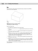
dimensioning is an important first step. Figure 14-1 shows a typical
linear dimension.
The parts of a dimension are:
✦ Extension lines: These extend from the dimensioned object to
the dimension line and arrowheads. A small gap usually sepa-
rates the dimensioned object and the start of the extension
lines. Extension lines visually clarify the extents of the object
being dimensioned.
In terms of dimensions, the word extension (or extend) is used in
two other ways besides referring to extension lines. First, the
extension line itself usually extends from the object being dimen-
sioned past the dimension line. You can specify the amount of this
extension. Second, in architectural dimensions, the dimension line
extends past the extension lines. You can specify this extension as
well.
Note
Cross-
Reference
✦✦✦✦
In This Chapter
Working with
dimensions
Drawing linear and
aligned dimensions
Dimensioning arcs,
circles, and angles
Creating ordinate
dimensions
Drawing leaders
Editing dimensions
✦✦✦✦
21_788864 ch14.qxp 5/22/06 7:21 PM Page 365
366
Part II ✦ Drawing in Two Dimensions
Figure 14-1: The parts of a dimension.
✦ Dimension text: This tells you the actual measurement of the dimensioned object. You
can format this text in decimals, fractions, scientific units, and so on.
✦ Dimension line: This extends between the extension lines.
✦ Arrowheads: These mark the intersection of the dimension line and the extension
lines. They can take several forms, such as tick marks, open arrows, or dots.
Dimensions have two interesting properties that you need to understand before you can suc-
cessfully work with them:
✦ Dimensions are blocks. I have mentioned blocks earlier in this book, and they are fully
covered in Chapter 18. Blocks are groups of objects that you can manipulate as one
object. As a result, if you pick a dimension, all parts of the dimension are selected.
✦ Dimensions are associative. This means that an association connects the dimension
and the object it dimensions. If you change the size of the object, the dimension auto-
matically adjusts appropriately.
All parts of a dimension can be formatted individually. You generally format a dimension by
creating a dimension style, which is a named set of formats for dimensions— just as a text
style is a named set of formats for text. (Dimension styles are the topic of the next chapter.)
Preparing to dimension
Dimensioning requires some preparation to get the result that you want. Before starting to
create dimensions, you should prepare as follows:
1. Create a layer for your dimensions. It’s important that dimensions be easily distinguish-
able from the rest of your drawing. The color is usually a contrast to that of your mod-
els. For example, if your models are black (and you’re working on a white screen), you
might want your dimensions to be green, magenta, or cyan.
If you often turn layers on and off (or freeze and thaw them), you may want to create a sep-
arate dimension layer for each layer of drawing data. For example, if you dimension an elec-
trical layer that you turn off regularly, you can have a special Dim-elec dimension layer that
you can turn off with the electrical layer.
Tip
Arrowhead
Line object
Extension line
Dimension text
Dimension line
21_788864 ch14.qxp 5/22/06 7:21 PM Page 366
367
Chapter 14 ✦ Drawing Dimensions
2. If you’re dimensioning an existing drawing that was created in a pre-2002 version of
AutoCAD or AutoCAD LT, turn on associative dimensioning with the DIMASSOC system
variable. Type dimassoc on the command line and type 2 ↵ at the prompt. (You can
also choose Tools➪ Options, click the User Preferences tab, and check the check box
in the Associative Dimensioning section of the dialog box. Then click OK.)
3. Create a text style for your dimensions.
Set the height of the text style to zero. You can then set the text height when you create the
dimension style. If you do specify a fixed height in your text style, that height overrides any
height that you specify in the dimension style.
4. Choose Tools ➪ Drafting Settings, click the Object Snap tab, and set the running object
snaps that you want. Endpoint and intersection are a necessity. Add center and quadrant
if you need to dimension arcs and circles. Click OSNAP on the status bar to turn it on.
5. Create a dimension style. The next chapter covers dimension styles.
6. Save your dimension layer, dimension text style, and dimension style in your drawing
templates.
The Dimension toolbar makes it easy to find the dimension commands quickly. The
Dimension menu offers most of the same commands as the toolbar. To display the Dimension
toolbar, right-click any toolbar and choose Dimension from the list.
Drawing Linear Dimensions
Just as the most common objects are lines, the most common dimensions are linear dimen-
sions. Use linear dimensions for lines, or a straight segment of a polyline, rectangle, or block.
You can also use a linear dimension for arcs and circles — you get the linear length of the arc
(not its perimeter length) and the diameter of the circle.
Specifying the dimensioned object
To dimension a line, choose Linear from the Dimension toolbar. The command responds
with the
Specify first extension line origin or <select object>: prompt. You
can now either pick two extension line origin points or press Enter and select an object for
dimensioning.
If you’re dimensioning more than one object, such as the distance from the endpoint of one
line to the endpoint of another line, pick the first extension line origin. At the
Specify sec-
ond extension line origin: prompt, pick the second extension line origin. The two points
on the objects that you pick define the length of the dimension.
If you’re dimensioning one object, press Enter at the
Specify first extension line origin
or <select object>: prompt. The Select object to dimension: prompt appears. Pick the
object.
Always use the Select Object option if possible for the most reliable results. Proper associa-
tion of dimensions with their objects depends on the points that you specify. If you can’t
select an object and the point you need to specify is an intersection, don’t click on the inter-
section. Instead, click on the object that you want to measure near the intersection and let
the object snap specify the intersection for you. If you’re not using the Select Object option,
always use an object snap for accuracy.
Caution
Tip
21_788864 ch14.qxp 5/22/06 7:21 PM Page 367
368
Part II ✦ Drawing in Two Dimensions
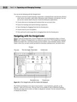
At the Specify dimension line location or [Mtext/Text/Angle/Horizontal/
Vertical/Rotated]: prompt, pick a point for the location of the dimension line. As you
move the mouse, you can see the results on your screen, as shown in Figure 14-2. If you want
an exact location, you can type in a relative coordinate, such as @0,.5 to specify that the
dimension line should be 0.5 units above the object. Snap mode may also work well for you,
depending on the drawing environment.
Figure 14-2: Picking a dimension line location for
a linear dimension.
Object snap tracking makes it a snap to pick points for dimensioning. For example, if you’re
dimensioning a house, your first extension line origin may be the outside corner of the house,
but the second extension line origin may be an inner wall. At the
Specify first extension
line origin or <select object>: prompt, move the cursor over the inner wall endpoint to
acquire it. Move the cursor back to the line you’re dimensioning and click when you see the
tooltip showing the snap point you chose. The dimension goes just where you need it.
The drawing used in the following exercise on drawing linear dimensions, ab14-a.dwg, is in
the Drawings folder on the CD-ROM.
STEPS: Drawing Linear Dimensions
1. Open ab14-a.dwg from your CD-ROM.
2. Save the file as
ab14-01.dwg in your AutoCAD Bible folder. This is a plan of a bed-
room, as shown in Figure 14-3. ORTHO and OSNAP should be on. Set a running object
snap for endpoint only. OTRACK should be off. The current layer should be set to Dim.
3. To display the Dimension toolbar, right-click any toolbar. Click Dimension. If you want,
drag the toolbar to the top or bottom of your screen until it docks.
On the
CD-ROM
Dimensioned object
Pick point
21_788864 ch14.qxp 5/22/06 7:21 PM Page 368
369
Chapter 14 ✦ Drawing Dimensions
Figure 14-3: A bedroom plan.
4. Choose Linear from the Dimension toolbar. Because you are dimensioning the
length of the room, you really want the dimension to be attached to the bottom
and top horizontal lines, so that if you move those lines to make the room longer or
shorter, the dimension changes. At the
Specify first extension line origin or
<select object>: prompt, pick 1 in Figure 14-3, close enough to the corner to get
the endpoint object snap marker. At the
Specify second extension line origin:
prompt, pick 2. At the Specify dimension line location or [Mtext/Text/Angle/
Horizontal/Vertical/Rotated]: prompt, move the cursor to the right until you
have sufficient space for the dimension text and click.
5. Repeat the DIMLINEAR command. At the
Specify first extension line origin or
<select object>: prompt, press Enter. At the Select object to dimension: prompt,
pick
3 (the window) in Figure 14-3. At the Specify dimension line location or
[Mtext/Text/Angle/Horizontal/Vertical/ Rotated]: prompt, move the cursor
down until you have sufficient space for the dimension text and click.
6. Save your drawing. It should look like Figure 14-4.
Using dimension options
You can also use one of the options offered at the command prompt to further control the
final dimension. Dimension options control the text and the angle of the dimension.
MText
The MText option lets you replace the calculated dimension text or add a prefix or suffix
to it. When you right-click and choose MText at the
Specify dimension line location or
[Mtext/Text/Angle/Horizontal/Vertical/Rotated]: prompt, the In-Place Text Editor
opens, as shown in Figure 14-5.
1
3
2
21_788864 ch14.qxp 5/22/06 7:21 PM Page 369
370
Part II ✦ Drawing in Two Dimensions
Figure 14-4: The bedroom with two linear
dimensions.
Figure 14-5: Changing the dimension text with the
In-Place Text Editor.
The best use of the MText option is to add some text before or after the measurement, such
as TYP “typical” (used when one dimension applies to several objects) or subject to final
approval. To add text before the measurement, simply start typing. To add text after the mea-
surement, press the End or Right Arrow key and then type. To replace the existing text, click the
text to select it and enter the replacement text. Then click OK to close the In-Place Text Editor.
Typing your own dimension text is most commonly used where a dimension represents sev-
eral sizes and refers to a size chart elsewhere in the drawing. For example, the text “Dim A”
might be used for this purpose. If you replace the existing text, you can obtain the original
text again by editing the dimension (double-click the dimension) and changing the Text
Override item in the Properties palette to <>.
If the measurement text itself does not appear the way you want it, you should change the
annotation specifications in the dimension style. You can also specify a prefix or suffix (such
as mm) for all dimensions, as I explain in the next chapter. You can delete the text and type
your own dimension text, but you lose the ability of the dimension’s measurement to auto-
matically adjust to any change in the object’s size.
Note
21_788864 ch14.qxp 5/22/06 7:21 PM Page 370
371
Chapter 14 ✦ Drawing Dimensions
To add text below the dimension line, enter \X after the dimension text. Any text after the \X
goes below the dimension line. The “X” must be uppercase.
Text
The Text option also lets you change dimension text but does not open the In-Place Text
Editor. Instead, you can quickly retype the entire dimension text as you want it on the com-
mand line.
Angle
The angle of the text (horizontal, vertical, or aligned) is specified in your dimension style.
However, you can use this option to change the angle of the dimension text for a particular
circumstance. Right-click and choose Angle to get the
Specify angle of dimension text:
prompt. Type in an angle or pick two points to align the text with an existing object.
Horizontal/vertical
The DIMLINEAR command assumes that you want a horizontal dimension if you select a hori-
zontal object or two definition points running horizontally — ditto for a vertical dimension.
Also, if you want to draw a vertical dimension of an object at an angle, you can specify this
simply by moving the mouse cursor horizontally when specifying the dimension line location,
as shown in Figure 14-6. If for some reason you need to force either a horizontal or vertical
dimension, you can use the vertical or horizontal options.
Figure 14-6: By dragging the mouse cursor to the right,
you can create a vertical dimension for this angled line.
The vertical dimension measures the change in the
Y coordinates of the line, not the length of the line.
Rotated
Use a rotated linear dimension when the length that you want to dimension is not parallel to
the extension line origins. Just as the vertical dimension in Figure 14-6 does not measure the
length of the line to which its extension lines extend, a rotated linear dimension does not
measure a specific object, but the distance of an imaginary line parallel to the dimension line.
Tip
21_788864 ch14.qxp 5/22/06 7:21 PM Page 371
372
Part II ✦ Drawing in Two Dimensions
Rotated dimensions are not very common, but when you need them, they’re the only way to
get the dimension measurement that you need.
To use a rotated dimension, start a linear dimension, pick the two extension line origins, and
choose the Rotated option. At the
Specify angle of dimension line <0>: prompt, type the
angle (or pick two points) to draw the dimension.
Figure 14-7 shows a hexagonal stepping-stone with a rotated linear angle. The extension lines
of the dimension extend to a line at 104.5 degrees, but in this case you want to measure a
length at an angle of 135 degrees. Note that the dimension really measures an imaginary line
parallel to the dimension line, shown in the figure as a dashed line, rather than the side of the
hexagon.
Figure 14-7: Drawing a rotated linear dimension for a
hexagonal stepping-stone.
Drawing Aligned Dimensions
When you want to dimension a linear object that is not orthogonal, use an aligned dimension.
The dimension lines of an aligned dimension are always parallel to the object, unlike rotated
dimensions. An aligned dimension measures the actual length of the object, not a vertical or
horizontal distance that you dimension with a linear dimension. Therefore, your choice of lin-
ear, linear rotated, or aligned dimension depends on the distance that you want to measure.
Figure 14-8 shows several aligned dimensions.
Figure 14-8: Three aligned dimensions.
21_788864 ch14.qxp 5/22/06 7:21 PM Page 372