autocad 2007 and autocad lt 2007 bible - phần 9 pptx
Bạn đang xem bản rút gọn của tài liệu. Xem và tải ngay bản đầy đủ của tài liệu tại đây (1.45 MB, 130 trang )
998
Part VI ✦ Customizing AutoCAD
Here are the other features of the Button Editor:
✦ Click Clear to clear the editing area and start from scratch.
✦ Click Open to open an existing button for editing. Button icons are stored as BMP files.
✦ Click Undo to undo your most recent action.
✦ Click Save As to save an existing BMP file under a new name. If you create a new
(or edited) button, use the Save As button and remember where you saved the BMP
file. The default is the main Support File Search Path location, which you can find
on the Files tab of the Options dialog box (Tools➪ Options).
✦ Click Save to save the button icon as a BMP file. The default filename is
ICON.bmp.
✦ Click Close to close the Button Editor.
✦ Click More to select a standard index color or true color. (True colors are available in
AutoCAD only.)
If you edited an existing button and saved the changes, then you’re done. However, if you
saved your button image under another file name (using the Save As button), you need to
associate the new filename with the toolbar button. In the Properties pane, click the Small
Image text box, and then click the Ellipsis (. . .) button. Browse to the BMP file and choose it.
Click Open. The file location appears in the Small Image text box. You can now click Apply, or
if you want to return to your drawing, click OK.
If you think you might ever want to display large toolbar buttons, do the same for the Large
Image text box. By default, when you create a button image, the Both option button is selected
in the Button Image section, and so you create both a small and a large image. To display
large toolbar buttons, choose Tools ➪ Options and click the Display tab. In the Window
Elements section, check the Use Large Buttons for Toolbars check box.
Creating flyouts
You can use the Customize User Interface dialog box to create your own flyouts, or you can
use one of the existing flyouts. To use an existing flyout, you just drag one toolbar onto
another one. Expand the Toolbars item in the Customizations In pane. Then expand the tool-
bar that you want to work with. In the same pane, locate the toolbar that you want to turn
into a flyout, and drag it to any location on the expanded toolbar.
To create your own flyout from scratch, follow these steps:
1. Expand the Toolbars item in the Customizations In pane.
2. Right-click any toolbar and choose New ➪ Flyout.
3. Right-click the new flyout (named Toolbar1 by default) and choose Rename. Type a
name for the flyout.
4. From the Command List pane, drag commands to the flyout, using the same technique
as described in the “Adding buttons” section earlier in this chapter.
The following exercise loads a partial customization file on top of the main customization file.
After the exercise, I explain how to undo the changes if you want. If you’re working on some-
one else’s computer, don’t do this exercise without that person’s permission. I explain more
about main and partial customization files in Chapter 33.
40_788864 ch29.qxp 5/22/06 7:38 PM Page 998
999
Chapter 29 ✦ Customizing Commands, Toolbars, and Tool Palettes
STEPS: Customizing Toolbars
1. Open Windows Explorer. Copy acad.cui (for AutoCAD) or acadlt.cui (for AutoCAD
LT) to a floppy disk, a CD-ROM, or your
AutoCAD Bible folder as a backup. If you use a
folder on your hard drive, be sure to press the Ctrl key as you drag the file so that you
copy it instead of moving it. If you don’t do this step, you won’t have a way to undo the
changes that you make to the menu file.
To find the location of these files, choose Tools ➪ Options and click the Files tab. Double-click
the Customization Files item, and then double-click the Main Customization File item to dis-
play the location of the menu file.
2. Start a new drawing using any template. Save the file as ab29-01.dwg in your AutoCAD
Bible folder.
3. Choose Tools➪ Customize ➪ Interface to open the Customize User Interface dialog box.
You should see
All Customization Files in the drop-down list. Double-click the
Toolbars item to expand it. Scroll down, and double-click the Zoom toolbar to expand it.
4. To delete a button from the Zoom toolbar, right-click the Zoom Center button (or the
button that you use least) and choose Delete. Confirm the deletion. Note that you can
preview the results in the Preview pane by clicking the toolbar name. Double-click the
Toolbars item again to collapse it. Click the Save All Current Customization Files button
to the right of the drop-down list.
5. To create a new toolbar, start by creating a new partial customization file. Click the
Transfer tab of the Customize User Interface dialog box.
6. From the drop-down list in the Customizations in Main CUI (left) pane, choose New.
From the drop-down list, choose Save As. In the Save As dialog box, type ab29-01 in
the File Name text box and click Save. (This saves the file in the Support folder, which
is the default location for CUI files.)
7. To load the new partial customization file,
ab29-01.cui, click the Customize tab. Make
sure that
All Customization Files shows in the Customizations In pane’s drop-down
list. If it doesn’t, choose it. To the right of the drop-down list, click the Load Partial
Customization File button. In the Open dialog box, choose
ab29-01.cui and click
Open. You see the filename in the drop-down list.
You may see a warning that workspace information in partial CUI files is ignored. This file
doesn’t have any workspace information in it, so click OK. I discuss workspaces in Appendix A.
8. To check that the new partial CUI file is loaded along with the main CUI file, choose
Main CUI File from the drop-down list. Double-click the Partial CUI files item. You
should see
ab29-01 on the list.
9. In the Customizations In pane, choose
All Customization Files from the drop-down
list. Double-click the
Partial CUI Files item and then double-click the AB29-01 item.
Right-click the Toolbars item and choose New➪ Toolbar. Type Special and press Enter.
(If the toolbar name is not selected and editable, right-click the new toolbar and choose
Rename. Then enter the new name.)
Note
Note
40_788864 ch29.qxp 5/22/06 7:38 PM Page 999
1000
Part VI ✦ Customizing AutoCAD
10. From the Command list drop-down list, choose All Commands. Find the Donut item and
drag it to the new
Special toolbar. You should see a left-pointing arrow when you have
dragged the command onto the toolbar.
11. From the Categories drop-down list in the Command List pane, choose the Modify cate-
gory and find Polyline. (This is the PEDIT command.) Drag it to your new toolbar.
To find a command in the long list, click any command and type the first letter of the com-
mand you want. The list jumps to the first command with that letter. You can then scroll
down and quickly find the command you want.
12. With All Commands displayed in the Categories List, drag the HIDE command (or Hidden
Visual Style) to the toolbar.
13. To create a custom command, click the New button to the right of the Categories drop-
down list. You see the new command listed as Command1 in the Properties pane.
14. Complete the Properties pane as shown in Figure 29-9. Type the macro as follows after
the
^C^C (which is already there), being careful to also include the spaces:
pedit \w .1 ;
15. Select the Special toolbar item. From the Categories drop-down list, choose Custom
Commands. Drag the
pline_tenth command to the Special toolbar.
16. With the pline_tenth button selected, in the Button Image pane, click the PEDIT icon. (It
looks similar to the icon in Figure 29-10.) Then choose Edit to open the Button Editor.
Figure 29-9: The completed Properties pane for
the custom command.
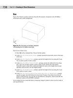
17. You want to change the button so that it looks as if a zero-width polyline is being changed
to a wider polyline, because that’s what the macro does. Click the red color. Choose the
Pencil tool (by default, it is already chosen). Click the Grid check box to help you work.
Click (or drag) the point of the Pencil tool in each box, using Figure 29-10 as a guide.
(Figure 29-10 shows the button in black and white.) When you’re done, click Save.
Tip
40_788864 ch29.qxp 5/22/06 7:38 PM Page 1000
1001
Chapter 29 ✦ Customizing Commands, Toolbars, and Tool Palettes
If you make a mistake, it’s easy to correct it. If you place a red pixel over an existing black
pixel, choose black and redraw the black pixel. If you place a red pixel in a wrong spot,
choose the Erase tool and click the pixel.
18. In the Create File dialog box, type pline_tenth in the File Name text box and click Save.
(Note that the file is saved in the Support\Icons folder by default.) Click Close.
Figure 29-10: You can create a new button in
the Button Editor.
19. To assign the icon to the button, in the Properties pane, click the Small Image item, and
then click the Ellipsis button to the right. In the Support\Icons folder where you saved
the icon file, choose
pline_tenth.bmp and click Open. (If you are using large icons,
use the Large Image item instead, or assign the icon to both.)
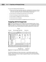
20. Click Apply. If necessary, move the dialog box so that you can see the new toolbar. If it
seems okay, click OK to close the Customize User Interface dialog box. (If not, continue
to make changes in the dialog box.) The toolbar should look like Figure 29-11.
If you don’t see the toolbar when you close the Customize User Interface dialog box, right-
click in any empty toolbar area (off all toolbars) and choose AS29-01 ➪ Special to display the
toolbar.
Figure 29-11: The custom toolbar contains four buttons.
21. Choose Polyline from the Draw toolbar and draw any series of polyline segments.
Choose the Pline_tenth button from the new toolbar. At the
Select polyline or
[Multiple]: prompt, pick the polyline. Its width changes to 0.1. (If it doesn’t work,
return to the Customize User Interface dialog box and check the macro.)
22. Save your drawing.
Note
Tip
40_788864 ch29.qxp 5/22/06 7:38 PM Page 1001
1002
Part VI ✦ Customizing AutoCAD
Here’s how the pedit macro that you used in the previous exercise works:
pedit \w .1 ;
1. Pedit issues the PEDIT command. The space after pedit is equivalent to pressing
Enter after you’ve typed the command on the command line. The PEDIT command then
displays the
Select polyline: prompt.
2. The backslash (
\) is a special character that pauses the macro for your input. When
you select the polyline, the macro continues, displaying the
Enter an option [Close/
Join/Width/Edit vertex/Fit/Spline/Decurve/Ltype gen/Undo]: prompt.
3. The
w then specifies the Width option. The space following it is like pressing Enter. The
PEDIT command then displays the
Specify new width for all segments: prompt.
4. The macro then specifies 0.1. The space after it is like pressing Enter again. The PEDIT
command then issues the
Enter an option [Close/Join/Width/Edit vertex/Fit/
Spline/Decurve/Ltype gen/Undo]: prompt.
5. The macro then uses a semicolon, which is used to specify pressing Enter at the end of
a menu macro. This ends the command.
Customizing Tool Palettes
Tool palettes give you quick access to blocks, hatches, and commands. I cover tool palettes
in Chapter 26. You can perform some customization directly on the tool palettes themselves.
Here I explain the procedure for customizing the tool palettes using the Customize dialog box.
To customize tool palettes, choose Tools ➪ Customize ➪ Tool Palettes to display the Customize
dialog box, shown in Figure 29-12. The current tool palettes are listed. Remember that each
tab on the Tool Palette window is considered a separate tool palette.
Undoing Toolbar Changes
To undo the changes that you made, you need to take two steps. To unload the partial cus-
tomization file, right-click it in the Customize User Interface dialog box and choose Unload.
Confirm the decision. This file is separate from the main customization file, and so it doesn’t
affect the main customization file directly.
To undo the changes that you made to the main customization file (
acad.cui or acadlt.cui),
you need to copy the original file over the new one. To find the location of this file, choose Tools ➪
Options and click the Files tab. Double-click the Customization Files item, and then double-click the
Main Customization File item.
Close AutoCAD. In Windows Explorer, locate the backup copy that you made in Step 1 of the pre-
vious exercise. Expand the location of the current main customization file. Press Ctrl and drag the
backup file to the current file of the same name.
When you open AutoCAD again, it will load the backup copy of the main customization file.
40_788864 ch29.qxp 5/22/06 7:38 PM Page 1002
1003
Chapter 29 ✦ Customizing Commands, Toolbars, and Tool Palettes
Figure 29-12: The Tool Palettes tab of the Customize
dialog box.
Use the Customize dialog box to customize tool palettes as follows:
✦ Change the order of the tool palette tabs: Select one of the tabs in the Tool Palettes
list and drag it up or down. You can also move the tabs directly on the Tool Palette by
right-clicking the tab name and choosing Move Up or Move Down.
✦ Create a new tool palette: Right-click and choose New Tool Palette. Enter a name and
press Enter. To create a new tool palette on the palette itself, right-click anywhere on
the palette and choose New Tool Palette.
✦ Rename a tool palette: Click the palette’s name to select it, and then click it again so that
you see a border around the name. Enter a new name and press Enter. To rename a tool
palette on the palette itself, right-click on the tab’s name and choose Rename Tool Palette.
✦ Delete a tool palette: Select the tool palette, right-click and choose Delete. In the Confirm
Tool Palette Deletion dialog box, which warns you that deletion is permanent unless
you first export the tool palette, click OK to delete the tool palette. You can also right-
click any tool palette and choose Delete Tool Palette.
✦ Import a tool palette or group: Right-click a palette or group and choose Import. In the
Import Palette dialog box, locate the XTP file and click Open.
✦ Export a tool palette group: Right-click a palette or group and choose Export. In the
Export Palette dialog box, choose the location for the file. You can change the name if
you want. The tool palette is saved as an XTP file. Click Save.
✦ Organize tool palettes into groups: In the Palette Groups area, right-click and choose
New Group. Enter a name for the group and press Enter. From the Tool Palettes list on
the left side of the dialog box, drag one or more tool palettes under the group name on
the right, as you see in Figure 29-12.
Note that the tool palettes come with a large number of dynamic blocks, and materials
(AutoCAD only).
40_788864 ch29.qxp 5/22/06 7:38 PM Page 1003
1004
Part VI ✦ Customizing AutoCAD
Summary
In this chapter, I covered the basics of customizing AutoCAD and AutoCAD LT. You started to
customize by:
✦ Creating command shortcuts (aliases) in the
acad.pgp or acadlt.pgp file
✦ Creating your own toolbars that can contain any command sequence that you need
✦ Customizing tool palettes, including importing, exporting, and creating groups
In the next chapter, you read about how to create macros with script files.
✦✦✦
40_788864 ch29.qxp 5/22/06 7:38 PM Page 1004
30
30
CHAPTER
Creating Macros
and Slide Shows
with Script Files
S
cript files are like macros that you create in your word processor
or spreadsheet. They automatically execute a series of commands.
You can use script files to automate plotting, set up a drawing, clean up
a drawing, create a slide show, or do any repetitive task. By running a
script file on a number of drawings, you can complete a time-consuming
task in a fraction of the time.
If you need to put together just a few commands that you might use
another time for other drawings, you may want to consider creating a
menu item or toolbar button instead. Chapter 29 explains how to cus-
tomize toolbars, and Chapter 33 explains how to customize menus.
Creating Macros with Script Files
A script file contains a list of commands and options. To create a
script file, you need to think out the commands that you want to exe-
cute, as well as their options and prompts. Then you create the text
for the script file. Script files have the following characteristics:
✦ They must use the
.scr filename extension.
✦ They are text-only (ASCII) files.
✦ They must use command-line syntax only (which can include
AutoLISP expressions).
Creating the script file
You can create the script file using a text editor, such as Notepad. For
early practice with script files, type each command on its own line. A
blank space is equivalent to pressing Enter. End each line by pressing
Enter (also called Return), without extra blank spaces. If you need
two returns, one after another, at the end of a line, use a blank line for
the second return. Every space is meaningful; getting those spaces
and blank lines right is probably the hardest part of creating a script
file. One technique is to start your script files in a word-processing
program that can display nonprinting characters (blank spaces and
✦✦✦✦
In This Chapter
Automating commands
with script files
Creating slide shows
Creating slide libraries
for menu customization
✦✦✦✦
41_788864 ch30.qxp 5/22/06 7:32 PM Page 1005
1006
Part VI ✦ Customizing AutoCAD
returns). You can either save the script file in text format or copy it into Notepad. Some tips
to help you create successful script files with the least aggravation are as follows:
✦ Before creating the script file, go through the steps once using only the command line.
Turn off the Dynamic Input feature for this purpose, because it doesn’t always include
all of the command-line content. (Click the DYN button on the status bar.)
✦ If the script includes commands that open a dialog box that asks for files, set the sys-
tem variable FILEDIA to zero (off) before experimenting with the commands that you’ll
use in the script file. This setting lets you practice the keystrokes without opening dia-
log boxes. You can also practice using the version of the command with the hyphen in
front of it (such as
-layer); however, in most cases, you don’t need the hyphen in the
actual script file.
Script files automatically run as if FILEDIA were off, even if it’s set to 1 (on). The FILEDIA sys-
tem variable determines whether dialog boxes appear for commands that let you open or
select files.
✦ For commands that require inputting text such as layer names or filenames, enclose
the names in quotation marks. Then, for the next use of Enter, press Enter and go to the
next line in the script instead of using a space. Otherwise, AutoCAD may misinterpret a
space as a space in the layer name or filename, rather than an Enter.
✦ Place comments in your script file to explain what you’re doing. A comment is any line
that starts with a semicolon.
✦ Keep Notepad open as you work. When you’ve completed a set of keystrokes that you
want, open the AutoCAD Text Window (press F2), select the command string that you
want, right-click, choose Copy, switch back to Notepad, and paste. Then cut out all of
the prompts, leaving only the keyboard entry. You’ll probably have to readjust the
spaces between the words.
✦ You can press End to check for blank spaces at the end of a line. Pressing Ctrl+End
moves the cursor to the end of the document; this is useful for checking for extra
spaces and lines at the end of a script.
Remember, you can open Notepad from within AutoCAD by typing Notepad at the command
line. At the
File to edit: prompt, press Enter to open a new file. (In AutoCAD LT, you need
to start Notepad from Windows.)
Another option is to write down what you type at the command line. As you write, use an
underscore to represent each space. It’s very hard to remember that you left three spaces
between two words unless you see three underscores. Of course, when you create the script
file, you must use spaces, not underscores.
As soon as you complete the script file, save it with any name that is meaningful to you, plus
an extension of
.scr.
Here’s an example of a script file that draws a series of circles:
circle 2,2 1.5
circle 6,2 1.5
circle 10,2 1.5
circle 14,2 1.5
This script file starts the CIRCLE command, specifies a center point, and specifies a radius,
four times. The results are shown in Figure 30-1.
Note
41_788864 ch30.qxp 5/22/06 7:32 PM Page 1006
1007
Chapter 30 ✦ Creating Macros and Slide Shows with Script Files
Figure 30-1: Running a script file created this drawing.
Taking Script Files to the Max
What if you want to execute that multi-cleanup script file on 200 drawings? Typing in all of those
filenames would take so long that you would wonder if you were saving any time.
However, you can save time. First, you need to find a text editor or word processor that can cre-
ate vertical blocks of text. This means that you can select columns of text rather than lines of text.
You can do this in Microsoft Word by holding down Alt and dragging down the text. (Use a fixed-
width font, such as Courier New, to make selecting columns of text easier.) Then, you need to
format the script file so that the entire set of commands is in one row, as in the figure shown
here. In Microsoft Word, you can use Page Setup to set the paper to landscape and make it as
wide as you need so that the text doesn’t wrap. (Of course, you type the script once, and then
copy the line and paste it as many times as you need.) You do this so that all of the filenames will
be in one column. Here you see the path but no filename at the end of each line. The filename
will be inserted before the quotation mark at the end of each line.
Now, open a DOS window. (From the Windows taskbar, choose Start ➪ Programs➪ Accessories ➪
Command Prompt.) Use the DOS
cd command to navigate to the folder where all of your drawings
are located. (They should all be in one folder.) Type dir *.dwg /b >dwglst.txt and press Enter. This
creates a listing of all of the files in that folder, and places it in a text file named
dwglst.txt. The
/b parameter creates a file that contains only the names of the drawings.
Open the file in a text editor or word processor that can create vertical blocks. Create a vertical
block over the drawing names and copy it to the Clipboard.
Open the script file in the same text editor or word processor, place the cursor at the top-left cor-
ner of the vertical block, and paste. You should get all of the drawing names inserted in the right
place, as shown here with two drawings. If you’re in a word processor, don’t forget to save the
file as a Text Only document.
Used in this way, the script files feature can be an extremely powerful tool for editing large num-
bers of drawings in one batch.
41_788864 ch30.qxp 5/22/06 7:32 PM Page 1007
1008
Part VI ✦ Customizing AutoCAD
Running a script file
You can run a script file from within a drawing. Use this technique when you want the script
to apply only to that drawing. However, you can also start a script within a drawing, then
close the drawing and continue on to open and run the same script in other drawings.
You can also run a script file when loading AutoCAD or AutoCAD LT. You would do this when
you want the script file to apply to more than one drawing. For example, you could use script
files in the following situations:
✦ You want to use a script file to set up every drawing that you open. Although the script
file applies to only one drawing at a time, you use it on a different drawing each time.
✦ You want to use a script file to clean up a list of drawings in one batch, such as thawing
all layers on all of the drawings in a folder.
Running a script file from within a drawing
If you want the script to apply only to the current drawing, then start the script from within
your drawing. To run a script from within a drawing, follow these steps:
1. Choose Tools➪ Run Script. This opens the Select Script File dialog box.
2. Choose the script file that you want.
3. Click Open. AutoCAD or AutoCAD LT runs the script file.
Running a script when loading AutoCAD or AutoCAD LT
To run a script when loading AutoCAD or AutoCAD LT, change the target expression that
Windows uses to open AutoCAD or AutoCAD LT. The easiest way to do this is to use the short-
cut to AutoCAD or AutoCAD LT on your desktop and modify the target there. Right-click the
AutoCAD or AutoCAD LT shortcut and choose Properties. Click the Shortcut tab, shown in
Figure 30-2.
Figure 30-2: The Shortcut tab of the AutoCAD
2007 Properties dialog box.
41_788864 ch30.qxp 5/22/06 7:32 PM Page 1008
1009
Chapter 30 ✦ Creating Macros and Slide Shows with Script Files
The Target text box displays the command expression that Windows uses to open AutoCAD
or AutoCAD LT. Don’t make any change to the current expression— just add to it. If you’re
using AutoCAD LT, substitute
aclt.exe for acad.exe and your AutoCAD LT program location
in the following examples. The format for starting a script file is:
drive:\path\acad.exe drive:\path\drawingname.dwg /b script_file
For example, if your current target reads C:\Program Files\AutoCAD 2007\acad.exe and
you want to open a drawing named
ba-349.dwg in c:\drawings and run a script file named
pre-plot.scr, your target should read:
“C:\Program Files\AutoCAD 2007\acad.exe” c:\drawings\ba-349.dwg
/b pre-plot
You don’t need to add the .scr extension after the script filename. Long file and folder names
that contain spaces must be enclosed in quotation marks, both in the target and in the actual
script file. You need to include the full path of the drawing. If the script file is not in the sup-
port file search path, include the entire path. For example:
“C:\Program Files\AutoCAD 2007\acad.exe” “c:\aec\drc\Dobbs Ferry
Apts.dwg” /b c:\aec\drc\cleanup
If you want to start a new drawing, you might want to specify a template. In the preceding for-
mat, replace the drawing filename with:
/t template_name
In Appendix A, I explain more about changing the target expression to open AutoCAD or
AutoCAD LT the way you want.
When you’ve finished typing your additions in the Target text box, click OK. Now, when you
start AutoCAD or AutoCAD LT, the drawing or template opens, and the script starts.
From within a script file, you can open (and close) other drawings. In this way, you can run a
script file on as many drawings as you want. Figure 30-3 shows a script file,
multi-cleanup.
scr, that you could use when loading AutoCAD or AutoCAD LT. The target is set to Apt 1A.dwg.
Figure 30-3: A script file that cleans up three drawings.
Unless you set the SDI (single document interface) system variable to 1, which disallows more
than one drawing to be open at a time, use the CLOSE command to close each drawing after
your script file has finished working on it. If you don’t, you may end up with 100 drawings open
at once, and probably a major computer crash as well!
Note
Cross-
Reference
41_788864 ch30.qxp 5/22/06 7:32 PM Page 1009
1010
Part VI ✦ Customizing AutoCAD
Here’s how multi-cleanup.scr works:
1. The CHPROP command selects all objects and sets their color to BYLAYER.
2. The LAYER command freezes the layer named
no-plot.
3. The script file saves the drawing.
4. The script file closes the drawing and opens the next drawing.
5. This process is repeated until the last drawing is edited and saved. The last drawing is
left open.
It’s helpful to leave the last drawing open so that when you return to see the results, you can
see that the last drawing has been properly edited. You then feel pretty sure that all of the
previous drawings were similarly edited.
Notice the quotation marks around the filenames in the script file. These are necessary
because the drawing filenames include spaces.
In the following exercise, you practice creating and using a script file similar to the multi-
cleanup script file used in the previous example, but for only one drawing.
The drawing used in the following exercise on creating and using a script file, ab30-a.dwg,
is in the Drawings folder on the CD-ROM.
STEPS: Creating and Using a Script File
1. Open ab30-a.dwg from the CD-ROM.
2. Save the file as
ab30-01.dwg in your AutoCAD Bible folder.
3. In Windows, choose Start ➪ Run. Type notepad and click OK.
4. Type the following, replacing the underscores with spaces. Note that there should be
two spaces between
all and c. Press Enter after the qsave line.
chprop_all__c_bylayer
-layer_f_no-plot
qsave
5. Save the file as cleanup.scr in your AutoCAD Bible folder. Close Notepad. The script
file changes the color property of all objects to ByLayer and freezes the no-plot layer.
Notice that the drawing has some text that has been set to a blue color (maybe to make
it more readable). The title block is on the no-plot layer.
6. Choose Tools➪ Run Script.
7. In the Select Script File dialog box, find
cleanup.scr in your AutoCAD Bible folder and
click Open. The script runs, changing the text’s color to ByLayer (green) and freezing
the no-plot layer. It also saves the drawing.
If the script file doesn’t work, press F2 to open the Text Window and see where the file
got hung up. This will help you see where to correct the script file. Reopen it and make
the correction. Save the file, close it, and try again.
8. Save your drawing.
On the
CD-ROM
Tip
41_788864 ch30.qxp 5/22/06 7:32 PM Page 1010
1011
Chapter 30 ✦ Creating Macros and Slide Shows with Script Files
Creating Slide Shows
You can create an image from the display on your screen and save it as a slide. You can use
several of these images to create a slide show. You can then use script files to direct the tim-
ing and order of the slide show. You first save a view of a drawing as a slide, create a slide
library from the slides, and then show the slides one after another automatically.
You can save any drawing as an image file and import it into a presentation program. You
can add text and special effects to create a professional slide show. For more information,
see Chapter 27.
Creating slides
Creating a slide is like capturing a screen shot of your drawing. AutoCAD or AutoCAD LT
makes a simplified vector file from the current viewport in model space, or from all viewports
in paper space layouts. You can create a slide of a wireframe or hidden display. However, you
cannot make a slide of a shaded or rendered display.
To create a slide, follow these steps:
1. Display the view of the drawing that you want to save as a slide.
2. Type mslide ↵.
3. In the Create Slide File dialog box, choose a location and name for the slide. Its file
extension will automatically be
.sld.
4. Choose Save.
Viewing slides
After you have created your slides, you will want to look at them! To view a slide, follow these
steps:
1. Type vslide ↵.
2. In the Select Slide File dialog box, choose the slide that you want to view.
3. Choose Open to display the slide.
Do a Redraw to return to your drawing. You cannot draw in or edit a slide.
The drawing used in the following exercise on creating and viewing slides, ab30-b.dwg, is
in the Drawings folder on the CD-ROM.
STEPS: Creating and Viewing Slides
1. Open ab30-b.dwg from the CD-ROM.
2. Save the file as
ab30-02.dwg in your AutoCAD Bible folder.
3. Type hide ↵ to hide the drawing.
4. Type mslide ↵. In the Create Slide File dialog box, click the Save In drop-down menu
and select your
AutoCAD Bible folder, if it isn’t already selected. In the File Name text
box, change the name from its default of
ab30-02.sld to ab30-02a.sld. Click Save.
On the
CD-ROM
Tip
41_788864 ch30.qxp 5/22/06 7:32 PM Page 1011
1012
Part VI ✦ Customizing AutoCAD
5. Choose View➪ 3D Views ➪ Viewpoint Presets. Change the value in the From XY Plane
text box to 60, and then click OK.
6. Issue the MSLIDE command again. This time, save the slide as
ab30-02b.sld.
7. Choose View➪ 3D Views ➪ Viewpoint Presets again. Change the value in the From XY
Plane text box to 90 and click OK.
8. Issue the MSLIDE command again and save the slide as
ab30-02c.sld.
9. Click Zoom Previous on the Standard toolbar (or choose View➪ Zoom ➪ Previous) until
you see the message
No previous view saved.
10. Type vslide ↵. In the Select Slide File dialog box, choose the first slide,
ab30-02a.sld.
Click Open. AutoCAD displays the slide.
11. Repeat the VSLIDE command and display
ab30-2b.sld. Do the same with
ab30-02c.sld.
12. Enter redraw all ↵ on the command line.
13. Save your drawing.
Using scripts to create slide shows
You can create a script file that displays slides one after another, resulting in a slide show.
You can use two special script file commands for this purpose:
✦ DELAY nnnn pauses the script for the number of milliseconds that you specify.
For example, DELAY 3000 pauses the script for 3 seconds.
✦ RSCRIPT repeats the script from the beginning. Use this command to create a con-
tinuously running script. To stop the script (whether repeating or not), press Esc or
backspace, or drop down any menu.
✦ RESUME restarts a script file after you’ve stopped it.
The VSLIDE command, which displays a slide, can also be used to preload the next slide into
memory. You use this command to preload a slide while viewers are looking at the previous
slide. This reduces the waiting time between slides. To use this feature, put an asterisk (
*)
before the filename in the VSLIDE command. The next VSLIDE command detects that a slide
has been preloaded and displays it without asking for the slide name. Here’s how it works:
1 vslide ab30-02a
2 vslide *ab30-02b
3 delay 3000
4 vslide
5 vslide *ab30-02c
6 delay 3000
7 vslide
8 rscript
This script file does the following:
Line 1 displays
ab30-02a.sld.
Line 2 preloads
ab30-02b.sld.
Line 3 waits 3 seconds, displaying
ab30-02a.sld.
Line 4 displays
ab30-02b.sld.
41_788864 ch30.qxp 5/22/06 7:32 PM Page 1012
1013
Chapter 30 ✦ Creating Macros and Slide Shows with Script Files
Line 5 preloads ab30-02c.sld.
Line 6 waits 3 seconds, displaying
ab30-02b.sld.
Line 7 displays
ab30-02c.sld.
Line 8 repeats the script from the beginning.
The Dynamic Input feature sometimes interferes with a slide show. If so, turn off Dynamic
Input (click the DYN button on the status bar) before running the slide show.
STEPS: Creating a Slide Show
1. Open Notepad and type the following script:
vslide ab30-02a
vslide *ab30-02b
delay 3000
vslide
vslide *ab30-02c
delay 3000
vslide
delay 3000
rscript
2. Remember to press Enter at the end of the last line. Save the file as ab30-02.scr in
your
AutoCAD Bible folder. Close Notepad.
3. To ensure that AutoCAD can find the slide files, place your
AutoCAD Bible folder in the
support file search path. To do this, choose Tools ➪ Options and click the Files tab.
Click Support File Search Path and then click Add. Click Browse and find your
AutoCAD
Bible folder. Click OK twice.
4. In any drawing, choose Tools➪ Run Script. Locate
ab30-02.scr in your AutoCAD
Bible folder and click Open. The slide show runs. Notice that the last slide still takes a
while to display.
5. Let the slide show run through twice. The last slide displays a little more quickly the
second time. Press Esc to stop the slide show.
6. Don’t save your drawing.
When running a slide show, you might want to maximize the screen area by reducing menu
and command-line space. You can use the CLEANSCREEN command (press Ctrl+0) to toggle
the toolbars and palette windows on and off. You can also hide (and redisplay) the com-
mand-line window by pressing Ctrl+9.
Creating Slide Libraries
You can organize your slides into slide libraries. Slide libraries have a .slb file extension.
One reason for creating slide libraries is to create image tiles when you’re customizing your
menu. If you’re using AutoCAD, then you can see an example of an image tile menu by choos-
ing Draw ➪ Surfaces ➪ 3D Surfaces. These image tiles are created with slides organized into
libraries.
Tip
Note
41_788864 ch30.qxp 5/22/06 7:32 PM Page 1013
1014
Part VI ✦ Customizing AutoCAD
To view slides in a library, use the following format:
library(slidename)
For example, you can place the three slides that you used in the preceding exercise in a slide
library called
3dmodel.slb. You can then use the following command in the script file to
preload the second slide (the second line of the script file):
vslide *3dmodel(ab30-02b)
To create a slide library, you need to use the DOS prompt. You use the SLIDELIB utility, which
you can find in your
AutoCAD 2007 or AutoCAD LT 2007 folder.
To get to the DOS prompt, choose Start ➪ Programs ➪ Accessories ➪ Command Prompt.
Follow these steps to create a slide library:
1. Create a text file (you can use Notepad) that contains the names of the slide files.
Include the paths of the slide files if they’re not in the support file search path. Place
each slide filename on a new line. Save the file as
ab30sld.lst.
SLIDELIB can read a listing that was created using DOS’s dir command with the /b param-
eter, which creates a simple listing of just the filenames. Therefore, you can place all of the
slide files in a folder and redirect the dir listing to a file. For example, you can create a list
named ab30sld.lst by typing the following at the DOS prompt:
dir *.sld /b >ab30sld.lst
This creates the list in the same folder as the slide files.
2. Assuming that you’re still in the same folder where you created the slide file list and you
want to create a library called
ab30sld.slb in the same folder, type the following at the
DOS prompt (substituting the actual path to your AutoCAD or AutoCAD LT program):
“c:\Program Files\ AutoCAD 2007\slidelib” ab30sld < ab30sld.lst
SLIDELIB cannot accept filenames with spaces, but it can handle long filenames, provided that
you use a character, such as an underscore, where you might normally have a blank space.
Summary
This chapter explained how to create script files to automate repetitive commands. You read
about the following:
✦ Creating script files that contain commands, options, and values in command-line format
✦ Running script files from within a drawing or when loading AutoCAD or AutoCAD LT
✦ Creating slides from the display in your viewport and creating a script file that displays
several slides, one after another, thus resulting in a slide show
✦ Organizing your slides into slide libraries
In the next chapter, you read about how to create your own linetypes and hatch patterns.
✦✦✦
Note
Tip
41_788864 ch30.qxp 5/22/06 7:32 PM Page 1014
31
31
CHAPTER
Creating Your Own
Linetypes and
Hatch Patterns
A
utoCAD and AutoCAD LT come with a large number of linetypes
and hatch patterns. However, when these do not serve your par-
ticular needs, you can create your own linetypes and hatch patterns.
You can then use them in your drawings in the same way that you use
the linetypes and hatch patterns that come with the software.
Linetypes are useful whenever you don’t want a continuous linetype.
They apply not only to lines, but also to polylines, arcs, ellipses, wire-
frames, and solids — in fact, to most objects. You use hatch patterns
to fill in closed (or almost closed) areas. Hatch patterns often repre-
sent textures or materials.
Creating Linetypes
There are two types of linetypes: simple and complex. Simple line-
types consist of only dashes and dots. Complex linetypes usually
have dashes and/or dots, but also contain text and/or shapes.
The default linetype file is
acad.lin for AutoCAD and acadlt.lin
for AutoCAD LT. You can add your own linetype definitions to this file
or create your own linetype files. Linetype files are text files and must
have a
.lin file extension. Of course, be sure to make a backup copy
of
acad.lin or acadlt.lin before you edit it. You commonly use
Notepad to edit a linetype file.
Creating simple linetypes
In the syntax for creating simple linetypes, each linetype is defined
using two lines of text. The first line contains the linetype name and
an optional description, formatted as follows:
*linetype name[, description]
✦✦✦✦
In This Chapter
Creating linetypes
Creating hatch patterns
✦✦✦✦
42_788864 ch31.qxp 5/22/06 7:37 PM Page 1015
1016
Part VI ✦ Customizing AutoCAD
Here are some points to remember:
✦ Always start the definition with an asterisk.
✦ The description is limited to 47 characters.
✦ If you include a description, precede it with a comma.
The second line of the linetype syntax is its definition. With simple linetypes, you’re limited to
dashes, dots, and spaces, which are measured in units and specified as follows:
✦ A dash is indicated by a positive number.
✦ A dot is indicated by a 0.
✦ A space is indicated by a negative number.
✦ Each item is separated by a comma, there are no spaces, and the maximum line length
is 80 characters.
✦ Each line must start with the letter A.
The following definition creates a line with two dashes of 0.25 units, followed by two dots, all
separated by spaces of 0.1 units.
*seeingdouble, Future hedge line
A,.25,–.1,.25,–.1,0,–.1,0,–.1
The result is shown in Figure 31-1.
Figure 31-1: The seeingdouble linetype.
If you feel quite confident, you can even create linetypes on the fly, using the command-line
form of the LINETYPE command. Type -linetype ↵ and use the Create option. Follow the
prompts and type the linetype definition on the command line. If you make a mistake, you
must open the linetype file in a text editor to make your corrections.
If your linetype definition will include both dashes and dots, you’ll get the best results when
you start the linetype definition with a dash. Starting the definition with a dash is a matter of
aesthetics, perhaps, but such a line connects better to other lines.
STEPS: Creating a Simple Linetype
1. Create a drawing using the acad.dwt or acadlt.dwt template.
2. Save your drawing as
ab31-01.dwg in your AutoCAD Bible folder.
Tip
42_788864 ch31.qxp 5/22/06 7:37 PM Page 1016
1017
Chapter 31 ✦ Creating Your Own Linetypes and Hatch Patterns
3. In Windows, choose Start ➪ Run. Type notepad and click OK to open Notepad.
4. Type the following:
*3dotsandadash, temporary fencing
A,.5,–.25,0,–.1,0,–.1,0,–.25
5. Press Enter after the last line. Save the file as ab31-01.lin in your AutoCAD Bible
folder and close Notepad.
6. In your drawing, choose Layer Properties Manager on the Layers toolbar, and then
click the New Layer icon. Name the new layer
tfence. Set its color to red.
7. Click Continuous in the Linetype column to open the Select Linetype dialog box.
Click Load.
8. In the Load or Reload Linetypes dialog box, click File. In the Select Linetype File dialog
box, find
ab31-01.lin in your AutoCAD Bible folder, choose it, and click Open.
9. Back in the Load or Reload Linetypes dialog box, choose
3dotsandadash and
click OK.
10. Again, in the Select Linetype dialog box, choose
3dotsandadash and then click OK.
The layer
tfence now shows the correct linetype. Click Current and then click OK.
11. Start the LINE command and turn on ORTHO. Draw any line to see the linetype. Save
your drawing. The linetype should look like Figure 31-2.
Figure 31-2: The
3dotsandadash linetype.
Creating complex linetypes
A complex linetype includes either shapes or text in the linetype definition. Complex linetype
definitions are similar to those for simple linetypes, except that they add a definition for a
shape or text. Figure 31-3 shows an example of each type.
Figure 31-3: Complex linetypes include shapes or text.
42_788864 ch31.qxp 5/22/06 7:37 PM Page 1017
1018
Part VI ✦ Customizing AutoCAD
Shapes are covered in the next chapter. At this point, you only need to know that shapes are
contained in files with the file extension
.shx.
The first line of the linetype definition is the same as for simple linetypes. The second line of
the definition can contain all of the same features as those for a simple linetype. However,
you add the special shape or text definition in square brackets:
✦ Syntax for shapes:
[shapename,shxfilename,details]
✦ Syntax for text: [“text string”,textstyle,details]
details refers to an optional series of rotation, scale, and offset specifications that you can
add to the definition. Table 31-1 describes these specifications.
The following complex linetype definition uses a shape and has no details:
*TEMPFENCE, FENCE SHAPE AND DASH
A,.5,–.25,[FENCE,”C:\AUTOCAD BIBLE\FENCE.SHX”],–.5
The specification for the shape is simply part of the rest of the definition that includes a dash
and spaces before and after the shape. The shape is enclosed in both commas and square
brackets. The first part of the shape definition is the name of the shape (which is defined in
the shape’s definition file), and the second part is the name of the shape file. In this case, the
shape file is not in the support file search path, so the entire path needs to be specified. Don’t
forget to use quotation marks around the shape filename if the folder name or filename con-
tains embedded spaces.
Note that the space after the shape (created with the –.5 code) is larger than the space
before it (created with the –.25 code). You need to allow for the space that the shape takes
up. This is largely a matter of trial and error, but if you know the shape definition well, you
can make a good estimate. If you need to go back and change the linetype definition, don’t
forget to reload the linetype (using the Load option).
The following complex linetype definition uses text and has no details:
*TFENCE, DASH & TEXT
A,.5,–.25,[“TEMP FENCE”,FENCE],–1.5
Again, the specification for the text is placed within a linetype definition that includes a dash
and spaces. The first part of the text definition is the text string, which is always in quotation
marks. The second part of the definition is the text style. As with the previous linetype defini-
tion containing a shape, the space after the text is larger than the space before in order to
leave enough room for the text.
You must define the text style in the drawing before you load the linetype.
Table 31-1 lists the details that you can add to both the shape and text parts of complex line-
type definitions.
Tip
42_788864 ch31.qxp 5/22/06 7:37 PM Page 1018
1019
Chapter 31 ✦ Creating Your Own Linetypes and Hatch Patterns
Table 31-1: Optional Details for Shapes and
Text in Complex Linetype Definitions
Detail Syntax Description
Relative R=## Rotates the shape or text relative to the angle of the line that you draw.
rotation This number is in degrees unless you put a g (for grads) or r (for radians)
after it.
Absolute A=## Rotates the shape or text based on the World Coordinate System,
rotation regardless of the angle of the line. Because the default is a relative
rotation of 0, you can use absolute rotation to keep the text facing upright,
regardless of the direction of the line. This number is in degrees unless you
put a g (for grads) or r (for radians) after it.*
Scale S=## Scales the text or shape. This scale is multiplied by any scale that is
contained in a shape definition or height in a text style. If you use a text
style with a height of 0, this scale number defines the text’s height.
X offset X=## A positive number moves the shape or text toward the endpoint of the
line. A negative number moves the shape or text towards the start
point of the line. You can use an X offset to place a shape or text along a
continuous linetype. You can also use an X offset to adjust the spacing of
a shape or text between dashes, instead of changing the spaces before
or after the dashes.
Y offset Y=## Moves the shape or text perpendicular to the direction of the line. A
positive number moves the shape or text up if the line is drawn from left
to right. Use a Y offset to center text and shapes along a linetype.
* Although using an absolute rotation of 0 might sound like a good idea for complex linetypes with text, if you
use the linetype at varying angles or on curves, you may find that the text shifts to an undesirable location due
to the text’s justification point.
Here is a definition that includes a shape with a scale and a Y offset:
*TEMPFENCE, FENCE SHAPE AND DASH
A,.5,–.25,[FENCE,”C:\AUTOCAD BIBLE\FENCE.SHX”,S=.025,Y= 07],–.5
This shape definition scales the shape to 0.025 of its original size. This results in the linetype
shown in Figure 31-4. Of course, in order to scale the shape, you need to know its original size.
You can use the SHAPE command to insert a shape and get an idea of what it looks like. In this
case, the shape’s original definition is much too large for a linetype and needs to be scaled down.
Figure 31-4: The TEMFENCE linetype.
The shape definition also moves the shape in the minus Y direction by 0.07 units. This cen-
ters the shape nicely within the linetype.
42_788864 ch31.qxp 5/22/06 7:37 PM Page 1019
1020
Part VI ✦ Customizing AutoCAD
When you create drawings using shapes or custom fonts, as in the case of complex linetypes,
you need to include the shape files or font files when you distribute the drawings to others.
By including more involved shapes in a complex linetype and not much else, you can create a
linetype that is mostly a series of shapes displayed one after the other. You can create some
interesting effects in this way.
You can find several complex linetypes at the end of the
acad.lin or acadlt.lin linetype
definition file. Look at their definitions and try them out to get ideas for your own complex
linetypes. The Express Tools installation (in AutoCAD only) has a command, MKLTYPE
(choose Express➪ Tools ➪ Make Linetype) that automatically creates linetypes, even
complex ones.
To find the location of acad.lin or acadlt.lin, choose Tools➪ Options and click the Files
tab. Double-click the first item, Support File Search Path, to display the location of the support
files.
The drawing used in the following exercise on creating a complex linetype, ab31-a.dwg, is
in the Drawings folder on the CD-ROM.
STEPS: Creating a Complex Linetype
1. Open ab31-a.dwg from the CD-ROM.
2. Save the file as
ab31-02.dwg in your AutoCAD Bible folder. This drawing is a simple
plan for a trailer park.
3. Choose Format ➪ Text Style. Click New and type TVCABLE for the Style Name. Click OK.
In the Font Name drop-down list, choose Arial. Click Apply and then click Close.
4. In Windows, choose Start ➪ Run. Type notepad and click OK. Notepad opens. Type the
following:
*TV, Buried television cable
A,.5, 5,[“TV”,TVCABLE,S=.3,X= 1,Y= 15], 75
5. Choose File ➪ Save and save it in your AutoCAD Bible folder as ab31-02.lin.
6. Choose Layer Properties Manager from the Layers toolbar. Choose
Buried_cable and
click its Continuous linetype in the Linetype column. In the Select Linetype dialog box,
choose Load. Click File. Find
ab31-02.lin in your AutoCAD Bible folder, choose it,
and click Open.
7. In the Load or Reload Linetypes dialog box, choose
TV and click OK. Do the same in the
Select Linetypes dialog box. Click Current. Click OK.
8. Click Linetype Control from the Properties toolbar and choose Other. In the Linetype
Manager, click Show Details to display the Details section. Change the Global Scale
Factor to 192. Click OK.
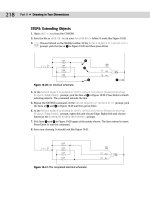
9. Draw some lines or polylines. Zoom in to see the linetype more clearly. Figure 31-5
shows the resulting linetype.
10. Save your drawing.
On the
CD-ROM
Note
Caution
42_788864 ch31.qxp 5/22/06 7:37 PM Page 1020
1021
Chapter 31 ✦ Creating Your Own Linetypes and Hatch Patterns
Figure 31-5: The TV linetype.
Creating Hatch Patterns
Hatch patterns are sets of line patterns that are used to fill an enclosed area. Although the
part of the hatch pattern definition that defines each line is similar to a linetype definition,
you also need to specify the angle and spacing of the lines. You cannot include text or shapes
in hatch patterns.
Hatch patterns are stored in files with a file extension of
.pat. The acad.pat or acadlt.pat
file includes a large number of hatch patterns. You can add to or edit this file, or create your
own
.pat file. As always, don’t forget to make a copy of acad.pat or acadlt.pat before you
edit it. When creating your own
.pat file, remember the following:
✦ If you aren’t adding patterns to
acad.pat or acadlt.pat, you can put only one hatch
pattern in a custom
.pat file. The filename and pattern name must be the same.
✦ You can insert comments in your
.pat file after a semicolon.
✦ You must press Enter after the end of the last line of the hatch definition.
To find the location of acad.pat or acadlt.pat, choose Tools ➪ Options and click the
Files tab. Double-click the Support File Search Path item, to display the location of the support
files.
The syntax for hatch patterns is as follows:
*pattern-name[, description]
angle, x-origin,y-origin, delta-x,delta-y [, dash1, dash2, ]
Here are some general points for hatch-pattern definitions:
✦ The pattern name cannot have spaces.
✦ The description is optional.
✦ Add the dash specifications only for noncontinuous lines.
✦ You can have more than one definition line (the second line in the syntax I just
showed), creating sets of hatch definitions that combine to create the hatch pattern.
Note
42_788864 ch31.qxp 5/22/06 7:37 PM Page 1021
1022
Part VI ✦ Customizing AutoCAD
✦ Each definition line can be no more than 80 characters.
✦ You can include a maximum of six dash specifications (which include spaces and dots).
✦ You can add spaces in the definition lines for readability.
Table 31-2 describes the features of a hatch-pattern definition.
Table 31-2: Hatch-Pattern Definitions
Specification Explanation
Angle Defines the angle of the lines in the hatch pattern. If you also specify an angle in
the Boundary Hatch dialog box (when you are placing the hatch), the two angles
are added. For example, if a hatch pattern defines lines at 105 degrees and you
specify a hatch angle of 30 degrees, you end up with lines running at 135 degrees.
X-origin Specifies the X coordinate of the base point of the hatch pattern. Your hatch
probably won’t go through 0,0; however, this point lines up sets of lines in hatch
patterns, as well as aligning hatch patterns in different areas. Because all hatch
patterns are calculated from the base point, they’re always aligned, no matter
where they actually appear in the drawing.
Y-origin Specifies the Y coordinate of the base point of the hatch pattern.
Delta-x Specifies the offset of successive lines. This applies only to dashed lines and is
measured along the direction of the lines. Specifying a delta-x staggers each
successive line by the amount that you specify so that the dashes don’t line up.
Delta-y Specifies the distance between lines, measured perpendicular to the direction of
the lines. This applies to both continuous and dashed lines.
Dash Defines a noncontinuous line using the same system as linetype definitions:
positive for a dash, negative for a space, and 0 for a dot.
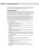
The hatch pattern shown in Figure 31-6 is the simplest form of hatch pattern.
Figure 31-6: The ftrailer hatch pattern with
continuous lines.
Although you could specify this simple hatch pattern in the Hatch and Gradient dialog box
(the Hatch dialog box if you are using AutoCAD LT), by specifying a user-defined hatch with
an angle and spacing, the example that follows shows the syntax clearly. The lines are at an
angle of 105 degrees; the hatch pattern starts at 0,0; and the spacing between the lines is
0.5 units. The lines are continuous.
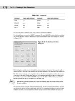
*ftrailer, proposed future trailers
105, 0,0, 0,0.5
42_788864 ch31.qxp 5/22/06 7:37 PM Page 1022