DISTRIBUTED AND PARALLEL SYSTEMSCLUSTER AND GRID COMPUTING 2005 phần 2 potx
Bạn đang xem bản rút gọn của tài liệu. Xem và tải ngay bản đầy đủ của tài liệu tại đây (899.12 KB, 23 trang )
glogin - Interactive Connectivity for the Grid
11
2. This solution has already been shown at the CrossGrid-Conference in Poznan in summer 2003, but
at that time, secure communication between the client and the remote program had not been implemented.
References
[Basu03] Sujoy Basu; Vanish Talwar; Bikash Agarwalla; Raj Kumar: Interactive Grid Archi-
tecture for Application Service Providers, Technical Report, available on the internet from
/>July 2003
[Chas02] Philips, Chase; Von Welch; Wilkinson, Simon: GSI-Enabled OpenSSH
available on the internet from />January 2002
[Cros01] The EU-CrossGrid Project,
[Cros04] Various Authors: CrossGrid Deliverable D3.5: Report on the Result of the WP3 2nd
and 3rd Prototype pp 52-57, available on the internet from
/>Proto2Status.pdf
February 2004
[FoKe99] Foster, Ian; Kesselmann, Carl: The Grid, Blueprint for a New Computing Infrastruc-
ture, Morgan Kaufmann Publishers, 1999
[GTK] The Globus Toolkit, />[KuMi02] M. Kupczyk,
N. Meyer, B. Palak,
P.Wolniewicz: Roam-
ing Access and Migrating Desktop, Crossgrid Workshop Cracow, 2002
[Kran03] Kranzlmüller, Dieter; Heinzlreiter, Paul; Rosmanith, Herbert; Volkert, Jens: Grid-
Enabled Visualisation with GVK, Proceedings First European Across Grids Conference,
Santiago de Compostela, Spain, pp. 139-146, February 2003
[Linn00] Linn, J.: Generic Security Service Application Program Interface, RFC 2743, Internet
Engineering Task Force, January 2000
[OSSH] The OpenSSH Project,
[Perk90] Perkins; Drew D.: Point-to-Point Protocol for the transmission of multi-protocol data-
grams over Point-to-Point links, RFC 1171, Internet Engineering Task Force, July 1990
[Rekh96] Rekhter, Yakov; Moskowitz, Robert G.; Karrenberg, Daniel; de Groot, Geert Jan;
Lear, Eliot: Address Allocation for Private Internets, RFC 1918, Internet Engineering Task
Force, February 1996
[Rich98] T. Richardson, Q. Stafford-Fraser, K. Wood and A. Hopper: Virtual Network Com-
puting, IEEE Internet Computing, 2(1):33-38, Jan/Feb 1998
[Stev93] W. Richard Stevens Advanced Programming in the UNIX Environment, Addison-
Wesley Publishing Company, 1993
[Ylon96] Ylönen, Tatu. SSH Secure Login Connections over the Internet, Sixth USENIX Secu-
rity Symposium, Pp. 37 - 42 of the Proceedings, SSH Communications Security Ltd. 1996
/>This page intentionally left blank
PARALLEL PROGRAM EXECUTION
SUPPORT IN THE JGRID SYSTEM*
Szabolcs Pota
1
, Gergely Sipos
2
, Zoltan Juhasz
1,3
and Peter Kacsuk
2
1
Department of Information Systems, University of Veszprem, Hungary
2
Laboratory
of Parallel and Distributed Systems, MTA-SZTAKI, Budapest, Hungary
3
Department
of Computer Science, University of Exeter, United Kingdom
, , ,
Abstract
Keywords:
Service-oriented grid systems will need to support a wide variety of sequential
and parallel applications relying on interactive or batch execution in a dynamic
environment. In this paper we describe the execution support that the JGrid
system, a Jini-based grid infrastructure, provides for parallel programs.
service-oriented grid, Java, Jini, parallel execution, JGrid
1.
Introduction
Future grid systems, in which users access application and system services
via well-defined interfaces, will need to support a more diverse set of execution
modes than those found in traditional batch execution systems. As the use of
the grid spreads to various application domains, some services will rely on im-
mediate and interactive program execution, some will need to reserve resources
for a period of time, while some others will need a varying set of processors.
In addition to the various ways of executing programs, service-oriented grids
will need to adequately address several non-computational issues such as pro-
gramming language support, legacy system integration, service-oriented vs.
traditional execution, security, etc.
In this paper, we show how the JGrid [1] system – a Java/Jini [2] based
service-oriented grid system – meets these requirements and provides support
for various program execution modes. In Section 2 of the paper, we discuss
the most important requirements and constraints for grid systems. Section 3 is
the core of the paper; it provides an overview of the Batch execution service
*
This work has been supported by the Hungarian IKTA programme under grant no. 089/2002.
14
DISTRIBUTED AND PARALLEL SYSTEMS
that facilitates batch-oriented program execution, and describes the Compute
Service that can execute Java tasks. In Section 4 we summarise our results,
then close the paper with conclusions and discussion on future work.
2.
Execution Support for the Grid
Service-orientation provides a higher level of abstraction than resource- ori-
ented grid models; consequently, the range of applications and uses of service-
oriented grids are wider than that of computational grids. During the design
of the JGrid system, our aim was to create a dynamic, Java and Jini based
service-oriented grid environment that is flexible enough to cater for the vari-
ous requirements of future grid applications.
Even if one restricts the treatment to computational grids only, there is a set
of conflicting requirements to be aware of. Users would like to use various
programming languages that suit their needs and personal preferences while
enjoying platform independence and reliable execution. Interactive as well
as batch execution modes should be available for sequential and parallel pro-
grams. In addition to the execution mode, a set of inter-process communication
models need to be supported (shared memory, message passing, client-server).
Also, there are large differences in users’ and service providers’ attitude to
grid development; some are willing to develop new programs and services,
others want to use their existing, non-grid systems and applications with no or
little modification. Therefore, integration support for legacy systems and user
programs is inevitable.
3.
Parallel execution support in JGrid
In this section we describe how the JGrid system provides parallel execu-
tion support and at the same time meets the aforementioned requirements con-
centrating on (i) language, (ii) interprocess communication, (iii) programming
model and (iv) execution mode.
During the design of the JGrid system, our aim was to provide as much
flexibility in the system as possible and not to prescribe the use of a particular
programming language, execution mode, and the like. To achieve this aim,
we have decided to create two different types of computational services. The
Batch Execution and Compute services complement each other in providing
the users of JGrid with a range of choices in programming languages, execution
modes, interprocess communication modes.
As we describe in the remaining part of this section in detail, the Batch
Service is a Jini front end service that integrates available job execution en-
vironments into the JGrid system. This service allows one to discover legacy
batch execution environments and use them to run sequential or parallel legacy
user programs written in any programming language.
Parallel Program Execution Support in the JGrid System
15
Batch execution is not a solution to all problems however. Interactive execu-
tion, co-allocation, interaction with the grid are areas where batch systems have
shortcomings. The Compute Service thus is special runtime system developed
for executing Java tasks with maximum support for grid execution, including
parallel program execution, co-allocation, cooperation with grid schedulers.
Table 1 illustrates the properties of the two services.
The Batch Execution Service
The Batch Execution Service provides a JGrid service interface to traditional
job execution environments, such as LSF, Condor, Sun Grid Engine. This
interface allows us to integrate legacy batch systems into the service-oriented
grid and users to execute legacy programs in a uniform, runtime-independent
manner.
Due to the modular design of the wrapper service, various batch systems
can be integrated. The advantage of this approach is that neither providers nor
clients have to develop new software from scratch, they can use well-tested
legacy resource managers and user programs. The use of this wrapper service
also has the advantage that new grid functionality (e.g. resource reservation,
monitoring, connection to other grid services), normally not available in the
native runtime environments, can be added to the system.
In the rest of Section 3.1, the structure and operation of one particular im-
plementation of the Batch Execution Service, an interface to the Condor [3]
environment is described.
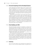
Internal Structure. As shown in Figure 1, the overall batch service con-
sists of the native job runtime system and the front end JGrid wrapper service.
The batch runtime includes the Condor job manager and N cluster nodes. In
addition, each node also runs a local Mercury monitor [4] that receives exe-
cution information from instrumented user programs. The local monitors are
connected to a master monitor service that in turn combines local monitoring
16
DISTRIBUTED AND PARALLEL SYSTEMS
Figure 1.
Structure and operation of the Batch Execution Service.
information and exports it to the client on request. Figure 1 also shows a JGrid
information service entity and a client, indicating the other required compo-
nents for proper operation.
The resulting infrastructure allows a client to dynamically discover the avail-
able Condor [3] clusters in the network, submit jobs into these resource pools,
remotely manage the execution of the submitted jobs, as well as monitor the
running applications on-line.
Service operation. The responsibilities of the components of the service
are as follows. The JGrid service wrapper performs registration within the
JGrid environment, exports the proxy object that is used by a client to access
the service and forwards requests to the Condor job manager. Once a job
is received, the Condor job manager starts its normal tasks of locating idle
resources from within the pool, managing these resources and the execution of
the job. If application monitoring is required, the Mercury monitoring system
is used to perform job monitoring. The detailed flow of execution is as follows:
1
2
Upon start-up, the Batch Execution Service discovers the JGrid informa-
tion system and registers a proxy along with important service attributes
describing e.g. the performance, number of processors, supported mes-
sage passing environments, etc.
The client can discover the service by sending an appropriate service
template containing the Batch service interface and required attribute
values to the information system. The Batch Executor’s resource prop-
Parallel Program Execution Support in the JGrid System
17
3
4
5
6
erties are described by Jini attributes that can be matched against the
service template.
The result of a successful lookup operation results in the client receiving
the proxy-attribute pair of the service.
The client submits the job by calling appropriate methods on the service
proxy. It specifies as method arguments the directory of the job in the
local file system, a URL through which this directory can be accessed,
and every necessary piece of information required to execute the job
(command line parameters, input files, name of the executable, etc.).
The proxy archives the job into a Java archive (JAR) file (5a), then sends
the URL of this file to the front end service (5b).
The front end service downloads the JAR file through the client HTTP
server (6a), then extracts it into the file system of a submitter node of the
Condor pool (6b).
As a result of the submit request, the client receives a proxy object rep-
resenting the submitted job. This proxy is in effect a handle to the job,
it can be used to suspend or cancel the job referenced by it. The proxy
also carries the job ID the Mercury monitoring subsystem uses for job
identification.
The client obtains the monitor ID then passes it - together with the MS
URL it obtained from the information system earlier - to the Mercury
client.
The Mercury client subscribes for receiving the trace information of the
job.
After the successful subscription, the remote job can be physically started
with a method call on the job proxy.
The proxy instructs the remote front end service to start the job, which
then submits it to the Condor subsystem via a secure native call. De-
pending on the required message passing mode, the parallel program
will execute under the PVM or MPI universe. Sequential jobs can run
under the Vanilla, Condor or Java universe.
The local monitors start receiving trace events from the running pro-
cesses.
The local monitor forwards the monitoring data to the master monitor
service
7
8
9
10
11
12
13
18
DISTRIBUTED AND PARALLEL SYSTEMS
14
The master monitor service sends the global monitoring data to the in-
terested client.
Once the job execution is finished, the client can download the result files
via the job proxy using other method calls either automatically or when re-
quired. The files then will be extracted to the location in the local filesystem as
specified by the client.
It is important to note that the Java front end hides all internal implementa-
tion details, thus clients can use a uniform service interface to execute, manage
and monitor jobs in various environments. In addition, the wrapper service can
provide further grid-related functionalities not available in traditional batch ex-
ecution systems.
The Compute Service
Our aim with the Compute Service is to develop a dynamic Grid execution
runtime system that enables one to create and execute dynamic grid applica-
tions. This requires the ability to execute sequential and parallel interactive and
batch applications, support reliable execution using checkpointing and migra-
tion, as well as enable the execution of evolving and malleable [5] programs in
a wide area grid environment.
Malleable applications are naturally suited to Grid execution as they can
adapt to a dynamically changing grid resource pool. The execution of these
applications, however, requires strong interaction between the application and
the grid; thus, suitable grid middleware and application programming models
are required.
Task Execution. Java is a natural choice for this type of execution due to its
platform independence, mobile code support and security, hence the Compute
Service, effectively, is a remote JVM exported out as a Jini service. Tasks sent
for execution to the service are executed within threads that are controlled by
an internal thread pool. Tasks are executed in isolation, thus one task cannot
interfere with another task from a different client or application.
Clients have several choices for executing tasks on the compute service. The
simplest form is remote evaluation, in which the client sends the executable
object to the service in a synchronous or asynchronous execute() method
call. If the task is sequential, it will execute in one thread of the pool. If it uses
several threads, on single CPU machines it will run concurrently, on shared
memory parallel computers it will run in parallel.
A more complex form of execution is remote process creation, in which case
the object sent by the client will be spawned as a remote object and a dynamic
proxy created via reflection, implementing the
TaskControl
and other client-
specified interfaces, is returned to the client. This mechanism allows clients
Parallel Program Execution Support in the JGrid System
19
e.g. to upload the code to the Compute Service only once and call various
methods on this object successively. The TaskControl proxy will have a
major role in parallel execution as shown later in this section.
A single instance of the Compute Service cannot handle a distributed mem-
ory parallel computer and export it into the grid. To solve this problem we
created a ClusterManager service that implements the same interface as the
Compute Service, hence appears to clients as another Compute Service in-
stance, but upon receiving tasks, it forwards them to particular nodes of the
cluster. It is also possible to create a hierarchy of managers e.g. for connecting
and controlling a set of clusters of an institution.
The major building blocks of the Compute Service are the task manager,
the executing thread pool and the scheduler. The service was designed in a
service-oriented manner, thus interchangeable scheduling modules implement-
ing different policies can be configured to be used by the service.
Executing Parallel Applications. There are several approaches to execut-
ing parallel programs using Compute Services. If a client discovers a multi-
processor Compute Service, it can run a multi-threaded application in parallel.
Depending on whether the client looks up a number of single-processor Com-
pute Services (several JVMs) or one multi-processor service (single JVM), it
will need to use different communication mechanisms. Our system at the time
of writing can support communication based on (i) MPI-like message pass-
ing primitives and (ii) high-level remote method calls. A third approach using
JavaSpaces (a Linda-like tuple space implementation) is currently being inte-
grated into the system.
Programmers familiar with MPI can use Java MPI method calls for commu-
nication. They are similar to mpiJava [6] and provided by the Compute Service
as system calls. The Compute Service provides the implementation via system
classes. Once the subtasks are allocated, processes are connected by logical
channels. The Compute Service provides transparent mapping of task rank
numbers to physical addresses and logical channels to physical connections to
route messages. The design allows one to create a wide-area parallel system.
For some applications, MPI message passing is too low-level. Hence, we
also designed a high level object-oriented communication mechanism that al-
lows application programmers to develop tasks that communicate via remote
method calls. As mentioned earlier, as the result of remote process creation, the
client receives a task control proxy. This proxy is a reference to the spawned
task/process and can be passed to other tasks. Consequently, a set of remote
tasks can be configured to store references to each other in an arbitrary way.
Tasks then can call remote methods on other tasks to implement the communi-
cation method of their choice. This design results in a truly distributed object
programming model.
20
DISTRIBUTED AND PARALLEL SYSTEMS
4.
Results
Both the Batch Execution Service and the Compute Service have been im-
plemented and tests on an international testbed have been performed. The
trial runs demonstrated (i) the ease with which our services can be discovered
dynamically with JGrid, (ii) the simplicity of job submission to native batch
environments via the Batch Execution Service, and the (iii) ability of the Com-
pute Service to run tasks of wide-area parallel programs that use either MPI or
remote method call based communication.
Further tests and evaluations are being conducted continuously to determine
the reliability of our implementations and to determine the performance and
overheads of the system, respectively.
5.
Conclusions and Future Work
This paper described our approach to support computational application in
dynamic, wide-area grid systems. The JGrid system is a dynamic, service-
oriented grid infrastructure. The Batch Execution Service and the Compute
Service are two core computational services in JGrid; the former provides
access to legacy batch execution environments to run sequential and parallel
programs without language restrictions, while the latter represents a special
runtime environment that allows the execution of Java tasks using various in-
terprocess communication mechanisms if necessary.
The system has demonstrated that with these facilities application program-
mers can create highly adaptable, dynamic, service-oriented applications. We
continue our work with incorporating high-level grid scheduling, service bro-
kers, migration and fault tolerance into the system.
References
[1]
[2]
[3]
[4]
[5]
[6]
The JGrid project: />Sun Microsystems, Jini Technology Core Platform Specification, />jini/specs.
M. J. Litzkow, M. Livny and M. W. Mutka, “Condor: A Hunter of Idle Workstations” 8th
International Conference on Distributed Computing Systems (ICDCS ’88), pp. 104-111,
IEEE Computer Society Press, June 1988.
Z. Balaton, G. Gombás, “Resource and Job Monitoring in the Grid”, Proc. of the Euro-Par
2003 International Conference, Klagenfurt, 2003.
D. G. Feitelson and L. Rudolph, “Parallel Job Scheduling: Issues and Approaches” Lecture
Notes in Computer Science, Vol. 949, p. 1-??, 1995.
M. Baker, B. Carpenter, G. Fox and Sung Hoon Koo, “mpiJava: An Object-Oriented Java
Interface to MPI”, Lecture Notes in Computer Science, Vol. 1586, p. 748-??, 1999.
VL-E: APPROACHES TO DESIGN A GRID-BASED
VIRTUAL
LABORATORY
Vladimir
Korkhov, Adam Belloum and L.O. Hertzberger
FNWI,
University of Amsterdam,
Kruislaan
403, 1098 SJ, Amsterdam, The Netherlands
Abstract
Keywords:
This paper addresses the issues of building Virtual Laboratory environments and
presents architecture of VL-E - a Grid-enabled virtual laboratory being devel-
oped at University of Amsterdam. The Virtual Laboratory concepts are usu-
ally described as having the objective to bridge the gap between the application
layer and lower layers that compose the infrastructure needed to support these
applications. In the Grid environment the core layer of middleware is usually
provided by toolkits like Globus ([Foster and Kesselman, 1998]) that enable
low-level functionality and encourage building higher level toolkits that would
offer new facilities, such as a robust access to different management facilities,
adequate fault tolerance in distributed systems, reliable super-scheduling tech-
niques, workflow support, web portal technology, advanced information man-
agement techniques and virtual reality visualization. Here we present a struc-
tural overview of VL-E and discuss some related issues brought up by nature of
Grid environment.
Grid, virtual laboratory, process flow, data flow, resource management
Introduction
The concepts of virtual laboratories have been introduced to support e-
Science, they address the tools and instruments that are designed to aid scien-
tists in performing experiments by providing high-level interface to Grid envi-
ronment. Virtual laboratories can spread over multiple organizations enabling
usage of resources across different organization domains. Potential e-Science
applications manipulate large data sets in distributed environment; this data is
to be processed regardless its physical place. It is thus of extreme importance
for the virtual laboratories to be able to process and manage the produced data,
to store it in a systematic fashion, and to enable a fast access to it. The vir-
22
DISTRIBUTED AND PARALLEL SYSTEMS
tual laboratory concepts encapsulate the simplistic remote access to external
devices as well as the management of most of the activities composing the
e-Science application and the collaboration among geographically distributed
scientists.
In essence the aim of the virtual laboratories is to support the e-Science
developers and users in their research, which implies that virtual laboratories
should integrate software designed and implemented independently and coor-
dinate any interaction needed between these components. Virtual laboratories
architecture thus has to take care of many different aspects, including a struc-
tural view, a behavioral view, and a resource usage view.
In this paper we present architecture and some major components of VL-E
environment - a virtual laboratory being developed at University of Amster-
dam.
1.
The Virtual Laboratory Architecture
The proposed architecture for VL-E environment is composed of two types
of components: permanent and transient. The life cycle of the transient com-
ponents follows the life cycle of common scientific experiment. The transient
components are created when a scientist or a group of scientists start an exper-
iment; they are terminated when the experiment is finished.
The core component of VL-E concept is a virtual experiment composed of
a number of processing modules which communicate with each other. From
the VL-E users point of view these modules are processing elements, users
can select them from a library and connect them via pairs of input and output
ports to define a data flow graph, referred to as a topology. From a resource
management point of view the topology can be regarded as a meta-application.
The modules can be considered as sub-tasks of that meta-application which
has to be mapped to Grid environment in a most efficient way. One of the aims
of our research work is the development of effective resource management
and scheduling schemes for Grid environment and VL-E toolkit. The model
of the VL scientific experiment we are considering in the work is extensively
explained in [Belloum et al., 2003].
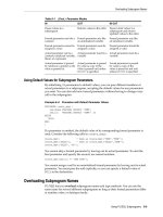
The components of the VL-E architecture are presented on figure 1. These
components are:
Session Factory: when contacted by a VL client, it creates an instance
of the Session Manager (SM) which controls all the activities within a
session.
Intersession Collaboration Manager: controls and coordinates the inter-
action of VL end-users cross sessions.
VL-E: Approaches to design a Grid-based Virtual Laboratory
23
Figure 1. VL-E Architecture
Module deployment: when a resource has been selected to execute an
end-user task (module), this component takes care of deploying the mod-
ule on this host and ensures that all the needed libraries are available.
Module cache: this component is in charge of optimizing the deploy-
ment of the VL module.
Module repository: this repository stores all the modules that can be
used to compose a virtual experiment.
VIMCO: is the information management platform of VL-E, it handles
and stores all the information about virtual experiments.
Session Manager: controls all the activities within the session
RTSM (Run-Time System Manager): performs the distribution of tasks
on Grid-enabled resources, starts distributed experiment and monitors
its execution.
RTSM Factory: creates an instance of Run-Time System Manager (RTSM)
for each experiment
24
DISTRIBUTED AND PARALLEL SYSTEMS
Resource Manager: performs resource discovery, location and selection
according to module requirements; maps tasks to resources to optimize
experiment performance utilizing a number of algorithms and schedul-
ing techniques.
Study, PFT and Topology Managers: components that implement the
concept of study introduced in section 2.
Assistant: supports the composition of an experiment by providing tem-
plates and information about previously conducted experiments.
2.
The concept of study in VL-E
One of the fundamental challenges in e-Science is the extraction of useful
information from large data sets. This triggers the need for cooperation of
multi-disciplinary teams located at geographically dispersed sites.
To achieve these goals, experiments are embedded in the context of a study.
A study is about the meaning and the processing of data. It includes descrip-
tions of data elements (meta-data) and process steps for handling the data. A
study is defined by a formalized series of steps, also known as process flow,
intended to solve a particular problem in a particular application domain. The
process steps may generate raw data from instruments, may contain data pro-
cessing, may retrieve and store either raw or processed data and may contain
visualization steps.
A Process Flow Template (PFT) is used to represent such a formalized work-
flow (Fig. 2). A study is activated by instantiating such a PFT. This instantia-
tion is called a process flow instantiation (PFI). A user is guided through this
PFI using context-sensitive interaction. The process steps in the PFT represent
the actual data flow in an experiment. This usually entails the data flow stem-
ming from an instrument through the analysis software to data storage facili-
ties. Consequently, an experiment is represented by a data flow graph (DFG).
This DFG usually contains experiment specific software entities as well as
generic software entities. We will call these self-contained software entities as
modules.
3.
Resource management in VL-E
One of the focuses of our research is the development of a resource man-
agement system for the VL-E environment. In this context, applications are
presented by a set of connected by data flow independent modules that per-
form calculations and data processing, access data storage or control remote
devices. Each module is provided with a “module description file” that in par-
ticular contains information about module resource requirements (called also
quality of service requirements - QoS). Our intention is to build a resource
VL-E: Approaches to design a Grid-based Virtual Laboratory
25
Figure 2. Process Flow Template (PFT)
management system that performs scheduling decisions based on this infor-
mation about modules requirements, dynamic resource information from Grid
information services (e.g. MDS, [Czajkowski et al., 2001]) and forecasts of
resource load (e.g. NWS, [Wolski et al., 1999]).
In the current design of VL-E architecture the Resource Manager (RM) is
connected to Run-Time System Manager Factory (RTSMF) which receives a
request to run an application (composed of a set of connected modules) from
the Front-End and sends the data about the submitted application with mod-
ule requirements (QoS) to RM, which performs resource discovery, location
and selection according to module requirements. RM composes a number of
candidate schedules that are estimated using specified cost model and resource
state information and predictions, optimal schedule is selected, resources used
in the schedule reserved, and the schedule is transmitted back to RTSMF. Then
RTSMF translates the schedule to Run-Time System for execution. During the
execution RM continues monitoring the resources in case rescheduling will be
needed.
The resource manager operates using application information, available re-
source information, cost and application models (Fig. 3). Application infor-
mation includes requirements, which define quality of service requested by
modules. These requirements contain values such as the amount of memory
needed, the approximate number of processing cycles (i.e. processor load),
26
DISTRIBUTED AND PARALLEL SYSTEMS
Figure 3. Resource Manager
the storage and the communication load between modules. We use RSL-like
language to specify these requirements (RSL is a resource specification Lan-
guage used in a the Globus toolkit to specify the job to be submitted to the Grid
Resource Allocation Manager, [Czajkowski et al., 1998]). Resource informa-
tion is obtained from the Grid information service (MDS) which also provides
forecasts of resource state from Network Weather Service (NWS). This helps
to estimate resource load in specified time frame in the future and model appli-
cation performance. The cost and application models are used by the resource
manager to evaluate the set of candidate schedules for the application. We have
conducted a number of experiments using different types of meta-scheduling
algorithms (several heuristic algorithms and simulated annealing technique),
the results and analysis are presented in [Korkhov et al., 2004].
4.
Related Work
During the last five years, both research and industrial communities have
invested a considerable amount of effort in developing new infrastructures that
support e-Science. Several research projects worldwide have started with the
aim to develop new methods, techniques, and tools to solve the increasing
list of challenging problems introduced by E-applications, such as the Virtual
Laboratories being developed at Monash University, Australia ([Buyya et al.,
2001]), Johns Hopkins University, USA ( />html), or at the University of Bochum in Germany ([Rohrig and Jochheim,
1999]). One important common feature in all these Virtual Laboratories pro-
jects is the fact that they base their research work on the Grid technology.
Furthermore, a number of these projects try to tackle problems related to a
specific type of E-application. At Johns Hopkins University researchers are
aiming at building a virtual environment for education over the WWW. Their
counterparts in Germany are working on a collaborative environment to allow
performing experiments in geographically distributed groups. The researchers
at Monash University are working on development of an environment where
large-scale experimentation in the area of molecular biology can be performed.
VL-E: Approaches to design a Grid-based Virtual Laboratory
27
Figure 4. MRI scanner experiment
These are just a few examples of research projects targeting issues related to e-
Science. Similar research projects are under development to support computa-
tional and data intensive applications such as the iVDGL (International Virtual
Data Grid Laboratory, DataTAG
(Research and Technological development for TransAtlantic Grid) ([D.Bosio
et al., 2003]), EU-DataGrid (PetaBytes, across widely distributed scientific
communities), PPDG (Particle Physics Data Grid, and
many others.
The VL-E approach differs from the other Virtual laboratory initiatives since
it took the challenge to address generic aspects of the expected virtual labora-
tory infrastructure. The aim of the VL-E project is not to provide a solution
for a specific E-application; instead, VL-E aims at supporting various classes
of applications.
5.
Conclusions
In this paper we introduced the architecture of VL-E environment which
supports a range of e-Science applications (material analysis experiment MAC-
28
DISTRIBUTED AND PARALLEL SYSTEMS
SLab, medical experiment with MRI scanner and some others). The proposed
VL-E architecture hides the low level details of Grid environment from scien-
tists allowing them to focus only on their domain of expertise. The services
offered by the VL-E middleware shield users from the complexity of binding
different infrastructures together. An example of running VL-E experiment is
presented on figure 4. Here the topology editor window is shown along with
X output of remote applications used to retrieve and analyse data from MRI
scanner.
In this paper we described the core concept of a study that lays in the ba-
sis of our virtual experimenting framework, addressed the issues of resource
management in Grid environment. Our research on resource management is
outlined in this paper, for more details please refer to [Korkhov et al., 2004].
This work has been partially funded by the Dutch BSIK project 03019:Vir-
tual Laboratory for e-science (VL-e).
References
[Belloum et al., 2003] Belloum, A., Groep, D., Hertzberger, L., Korkhov, V., de Laat, C. T.,
and Vasunin, D. (2003). VLAM-G: A Grid-based Virtual Laboratory. Future Generation
Computer Systems, 19(2):209–217.
[Buyya et al., 2001] Buyya, R., Branson, K., Giddy, J., and Abramson, D. (2001). The virtual
laboratory: Enabling molecular modeling for drug design on the world wide grid. Technical
report, Monash University.
[Czajkowski et al., 2001] Czajkowski, K., Fitzgerald, S., Foster, I., and Kesselman, C. (2001).
Grid Information Services for Distributed Resource Sharing. In The Tenth IEEE Interna-
tional Symposium on High-Performance Distributed Computing (HPDC-10). IEEE Press.
[Czajkowski et al., 1998] Czajkowski, K., Foster, I., Karonis, N., Kesselman, C., Martin, S.,
Smith, W., and Tuecke, S. (1998). A Resource Management Architecture for Metacomput-
ing Systems. In Proceedings of IPPS/SPDP ’98 Workshop on Job Scheduling Strategies for
Parallel Processing, pages 62–82.
[D.Bosio et al., 2003] D.Bosio, J.Casey, A.Frohner, and et al, L. (2003). Next generation eu
datagrid data management. In CHEP 2003, La Jolla - CA, USA.
[Foster and Kesselman, 1998] Foster, I. and Kesselman, C. (1998). The Globus Project: A
Status Report. In IPPS/SPDP ’98 Heterogeneous Computing Workshop, pages 4–18.
[Korkhov et al., 2004] Korkhov, V., Belloum, A., and Hertzberger, L. (2004). Evaluating Meta-
scheduling Algorithms in VLAM-G Environment. In to be published at the Tenth Annual
Conference of the Advanced School for Computing and Imaging (ASCI).
[Rohrig and Jochheim, 1999] Rohrig, C. and Jochheim, A. (1999). The virtual lab for con-
trolling real experiments via internet. In IEEE International Symosium on Computer-Aided
Control System Design, CACSD ’99, Hawaii.
[Wolski et al., 1999] Wolski, R., Spring, N., and Hayes, J. (1999). The Network Weather Ser-
vice: Distributed Resource Performance Forecasting Service for Metacomputing. Journal
of Future Generation Computing Systems, Volume 15, Numbers 5-6, pp. 757-768, October,
1999., (5-6):757–768.
SCHEDULING AND RESOURCE BROKERING
WITHIN THE GRID VISUALIZATION KERNEL*
Paul Heinzlreiter, Jens Volkert
GUP Linz
Johannes Kepler University Linz
Altenbergerstr. 69
A-4040 Linz
Austria/Europe
Abstract
Keywords:
The role of grid computing as a tool for computational science which has evolved
over the past years leads to additional requirements for grid middleware. One
of these requirements is visualization support which is provided by the Grid
Visualization Kernel (GVK). To enable proper usage of grid resources for visu-
alization purposes sophisticated scheduling and resource brokering mechanisms
are required. These mechanisms enable the automatic construction of a visu-
alization pipeline taking into account the requirements specified by the user as
well as resource availability.
Scheduling, resource brokering, grid computing, visualization
1.
Introduction
During the last years grid computing has evolved into a standard technique
for distributed high-performance and high-throughput computing by harness-
ing the resources of multiple organizations for running computational intensive
applications [9]. This is enabled by grid middleware toolkits such as Globus
[8], which has became the de facto standard grid middleware solution.
Compared to the rapid evolution of available middleware solutions which
currently provides a solid foundation of basic services, more application spe-
cific support by means of middleware extensions still offers a wide field for
improvements.
One of the key issues within the scientific computing domain is visualiza-
tion, which provides the scientist with the appropriate tool for result validation.
*The Grid Visualization Kernel (GVK) is partially supported by the Crossgrid Project of the European
Commission under contract number IST-2001-32243.
30
DISTRIBUTED AND PARALLEL SYSTEMS
Since typical grid computing applications operate on large datasets, the visu-
alization task itself also can benefit from the computational power available on
the grid. With this in mind, the Grid Visualization Kernel (GVK) [13], which
is composed of a set of specific visualization modules running on different grid
nodes, has been developed. GVK aims at providing the best visualization per-
formance possible given the type of the requested service and the status of the
available grid resources. This is enabled by splitting the requested visualiza-
tion pipeline into various subtasks, each of which is accomplished by a specific
visualization module.
Within this paper the main focus is put on the GVK visualization plan-
ner (VP) which identifies the required visualization subtasks and acts as a
application-specific resource broker by mapping the tasks onto the available
grid resources.
The remaining sections are structured as follows: In Section 2 an overview
over related work in field of distributed application scheduling is given. In Sec-
tion 3 an overview of the functionality of the VP is given, while the subsequent
sections elaborate the steps of the visualization planning process. Finally an
outlook on future work concludes the paper.
2.
Related Work
Various approaches have already been studied in the field of scheduling for
distributed applications. A good survey of the problems arising is given in
[1]. This paper focuses on the scheduling problem for distributed applications
communicating over heterogenous networks. The described approach focuses
on providing a specific scheduler for each application, thus taking into account
the application specific requirements.
In contrast to this method [6] describes a scheduling approach which is de-
coupled from the application to be executed. This is achieved by using a per-
formance model of the job to be scheduled.
The scheduling within Nimrod/G [3] focuses on running parameter studies
on the grid. It aims at providing economy based resource trading and offers
different scheduling strategies like time minimization, cost minimization, and
no minimization, which means that the task is scheduled for execution within
the given cost and time constraints.
In [14] the scheduling approach used within the EU Crossgrid project is
presented. The Crossgrid scheduling system consists of a scheduling agent, a
resource searcher, and an application launcher. The matchmaking between jobs
and resources is done by the resource searcher. It provides the scheduling agent
with different possible sets of resources, which selects the most appropriate
one.
GVK Scheduling and Resource Brokering
31
The scheduling approach chosen for the Condor-G system [10] uses a grid
manager process, which is started locally and handles the communication with
the remote resource. It also delivers status information on the remote job to the
local Condor-G scheduler. An additional task of the grid manager is detection
of remote resource failures.
Compared to these methods the scheduling within GVK is focused onto the
visualization domain and aims specifically at creating a visualization pipeline
possibly spreading multiple grid hosts.
3.
The GVK Visualization Planner
The visualization process as performed by GVK can be understood as a
series of transformations which lead from the input data to the final image.
The task of the VP is to identify a series of data transformations which have
to be applied to the data to generate the desired output. Its input is given by
the visualization request, which describes the visualization as requested by the
user of GVK. The output of the VP is a execution schedule for a set of grid
modules, which form an appropriate visualization pipeline for the requested
visualization task. The required modules are subsequently invoked using the
Globus GRAM [4] service. To enable this the VP delivers its results in the
form of RSL scripts [11].
During the visualization planning process the following informations have
to be determined:
Structure of the pipeline
Required modules
Interconnections between the modules
Visualization algorithms to be used
Execution locations for the modules
The task of the VP can be splitted into the following steps:
Task decomposition
Resource information gathering
Rendering algorithm selection
Resource mapping
Several factors are taken into account at different stages within the planning
process: The type of the requested visualization, the available software mod-
ules and the structure of the input data are evaluated during the first stage of
the planning process, the visualization task decomposition. The available grid
1
2
3
4
32
DISTRIBUTED AND PARALLEL SYSTEMS
resources are determined during stage two and are relevant for the rendering
algorithm selection and the resource mapping.
In order to cope with this complex scheduling and resource brokering prob-
lems, a top-down analysis of the problem is performed. Within the following
sections the different phases of the visualization planning process are elabo-
rated following their execution order.
4.
Visualization Task Decomposition
Within the first step of the visualization planning process the transformation
of the task described by the visualization request into an ordered set of modules
has to be performed.
The main factor which is determining this phase of the planning process is
the set of available software modules. At first it is required to check if all re-
quired software modules for the pipeline are available. The VP has access to
a list of available software modules, which is provided to the VP upon invo-
cation and identifies the modules, which can be started on various grid nodes
to be included into the visualization pipeline. It identifies which visualization
modules are already available in binary form on the available execution hosts.
If that is not the case the executable can be staged to the execution host using
the Globus GASS service [2]. The input and output formats of the modules as
well as the parallelism approach applied for the algorithm are taken as criteria
for evaluating their usability.
The functionality related part of the decision is done based on the data for-
mats which have been defined for the modules input and output interfaces. At
first the output format of a module has to match the input format of the sub-
sequent one. Additionally the input format of the first module and the output
format of the last have to be selected according to the specification in the visu-
alization request.
After a set of software modules has been identified for each stage of the
visualization pipeline, which satisfies the functionality related constraints, the
visualization planning process enters the next stage.
5.
Resource Information Gathering
Getting information about the available grid nodes is crucial for the VP.
The main source of resource-related information within a Globus-based grid
environment is the metadirectory service (MDS) [5,7]. It delivers information
on the static and dynamic aspects of resource availability on the grid.
To enable the selection of appropriate hosts access to aggregate informa-
tion about all accessible grid hosts is required. This is realized by accessing
a Grid Index Information Services (GIIS) server, which represents the aggre-
gate information source. The GVK VP retrieves the available grid hosts as
GVK Scheduling and Resource Brokering
33
well as information on processing power, available memory and file system
usage from the MDS system. For processors the number and speeds are re-
trieved, considering memory the total and free amount can be checked, and for
filesystems the free space and the location is reported. Other informations like
network and CPU loads are measured directly using GVK functionality, which
enables fast reaction if the network or system load changes significantly. The
GVK CPU load sensor has been realized by calling the unix
top
command and
is incorporated into the GVK resource information module which also delivers
the relevant parts of the MDS output to the VP. Information about the available
network bandwidth is collected by sending test data over the network connec-
tions in question. If a specific connection has already been identified as a re-
quired datapath payload data can already be transmitted during the bandwidth
measurements. The network monitoring then serves as a tool for selecting the
appropriate transmission mode such as compressed data transmission [12].
Within this stage of the visualization planning process all available grid
hosts are evaluated taking into account their static and dynamic properties.
6.
Algorithm Selection and Resource Mapping
During these stages of the visualization planning process the previously se-
lected software modules have to be mapped onto the available resources. The
output of stage one identifies a series of required data transformations repre-
senting the pipeline. For each data transformation a list of available modules
is provided, which offer the appropriate input and output interface. Based on
the resource information gathered in step two, the appropriate implementation
together with the fitting resource has to be found. The main problem of this
selection process is given by the mutual influence of resource and algorithm
selection.
In general, one can distinguish sequential algorithms (SQA), shared mem-
ory parallel algorithms (SMA), and distributed memory parallel algorithms
(DMA). The other criterion identified is the type of hardware. The VP makes a
distinction between a single processor system (SPS), a shared memory system
(SMS), and a distributed memory system (DMS).
For selecting an appropriate combination of algorithm and hardware the
possible combinations are evaluated considering their performance. The fol-
lowing table illustrates the performance gains or losses to be expected if the
according hardware-algorithm combination is used. For this comparison it was
assumed that each processor offers the same amount of computational power.
A plus sign denotes a performance gain, a minus a loss. The appearance of
a double plus or minus indicates a significant gain or loss. For a plus minus
combination no major performance impact compared to the single processor
and sequential algorithm pair is expected.