Adobe Illustrator CS4 bible phần 4 docx
Bạn đang xem bản rút gọn của tài liệu. Xem và tải ngay bản đầy đủ của tài liệu tại đây (3.21 MB, 76 trang )
200
Illustrator Basics
Part I
FIGURE 6.18
A path being reshaped using the Reshape tool
Cleaning up a path
Clean Up removes three unwanted elements from Illustrator documents: stray points, unpainted
objects, and empty text paths. Clean Up works on the entire document, regardless of what is
selected. You apply this command by choosing Object ➪ Path ➪ Clean Up. The Clean Up dialog
box is shown in Figure 6.19.
NOTE
NOTE
Clean Up doesn’t work on locked or hidden paths, paths turned into guides, or
paths on locked or hidden layers.
These are the Delete options in the Clean Up dialog box:
Stray Points: Selects and deletes any little points flying around. These points can cause
all sorts of trouble, as a point can have paint attributes but can’t print. This option actu-
ally deletes the points.
NOTE
NOTE
Select All Stray Points under the Select menu selects the points, but you have to
press Backspace or Delete to delete them.
09_345191-ch06.indd 20009_345191-ch06.indd 200 10/24/08 11:19:49 AM10/24/08 11:19:49 AM
201
Learning How to Select and Edit
6
Unpainted Objects: Eliminates any paths that are filled and stroked with None and that
aren’t masks (masks always have fills and strokes of None)
Empty Text Paths: Finds any text paths with no characters and then deletes them
FIGURE 6.19
Use the Clean Up dialog box to specify what elements you want to clean up.
NOTE
NOTE
Empty Text Paths isn’t the same as the old Revert Text Paths from previous
Illustrator versions, which changed empty text paths back into standard paths.
CROSS-REF
CROSS-REF
For more on text paths, see Chapter 9.
If you aren’t sure whether your document contains these three items, run Clean Up. If none of
these items are found, a message box, as shown in Figure 6.20, appears and tells you so.
FIGURE 6.20
This message tells you that there was nothing to clean up in your document.
09_345191-ch06.indd 20109_345191-ch06.indd 201 10/24/08 11:19:50 AM10/24/08 11:19:50 AM
202
Illustrator Basics
Part I
Offsetting a path
Offset Path, which you access by choosing Object ➪ Path ➪ Offset Path, draws a new path around
the outside or inside of an existing path. The distance from the existing path is the distance that
you specify in the Offset Path dialog box, which is shown in Figure 6.21. In a sense, you’re creat-
ing a stroke, outlining it, and uniting it with the original — all in one action. You can specify the
distance the path is to be offset by typing a value in the Offset box.
FIGURE 6.21
Use the Offset Path dialog box to specify how to create the new offset path.
A positive number in the Offset Path dialog box creates the new path outside the existing path, and
a negative number creates the new path inside the existing path. When the path is closed, figuring
out where Illustrator will create the new path is easy. When working with an open path — such as
a vertical line — the outside is the left side of the path and the inside is the right side of the path.
The Joins option allows you to select from different types of joins (which I discuss later in this
chapter) at the corners of the new path. The choices are Miter, Round, and Bevel, and the result is
the same effect that you get if you choose those options as the stroke style for a stroke.
The Miter limit affects the miter size only when you select the Miter option from the Joins drop-
down list (popup menu). However, the option is available when you select Round and Bevel joins.
Just ignore the Miter limit when you’re using Round or Bevel joins. (You can’t use a value that’s
less than 1.)
Often, when you’re offsetting a path, the new, resulting path overlaps itself. This creates small,
undesirable bumps in a path. If the bumps are within a closed-path area, select the new path and
then choose Unite from the Pathfinder panel. If the bumps are outside the closed-path area, choose
Divide from the Pathfinder panel and then select and delete each of the bumps.
TIP
TIP
If you’re thinking of using the Scale tool rather than Offset Path, you should know
that the Scale tool does something totally different from Offset Path. Offset Path
offsets lines around the original path equally. The Scale tool enlarges or reduces the path but
doesn’t add lines. Unless you’re using a perfect square or circle, stick to Offset Path. That way,
you get an even placement of the new path accurately around or inside the selected path.
09_345191-ch06.indd 20209_345191-ch06.indd 202 10/24/08 11:19:52 AM10/24/08 11:19:52 AM
203
Learning How to Select and Edit
6
Outlining a path
Outline Path creates a path around an existing path’s stroke. The width of the new path is directly
related to the width of the stroke.
I use Outline Path for two reasons. The first and most obvious reason is to fill a stroke with a gra-
dient. The second reason is that when you transform an outlined stroke, the effect is often different
from the effect that results from transforming a stroked path. Scaling an outlined stroke changes
the width of the stroke in the direction of the scale. The same is true when using the Free Distort
effect (Effect ➪ Distort & Transform ➪ Free Distort), which also changes the width of the stroke in
the direction of the scale. This sometimes results in a nonuniform-appearing stroke, which can’t be
achieved with a standard stroke. Figure 6.22 shows the difference between transforming/distorting
a stroked path and an outlined stroke. Both copies were scaled vertically to more clearly demon-
strate the different behaviors. With the stroked path, the transformation results in the stroke
expanding far beyond the fill, while with the outlined stroke, the two remain in sync.
Consider these options for outlining a path:
The End and Join attributes of the stroke’s style determine how the ends and joins of the
resulting stroke look.
Outline Path creates problems for tight corners. It causes overlaps that are similar to
those generated by Offset Path.
CAUTION
CAUTION
Using a Dash pattern on the stroke and using Outline Path changes the stroke back
to a solid line and then outlines it.
Looking under the Effect menu, you find a Path effect with the following options: Offset Path,
Outline Object, and Outline Stroke. These are the same as what is found by choosing
Object ➪ Path. However, under Effect, you can always go back and edit the options. Choosing the
Path functions from under the Object menu has a more permanent result.
CROSS-REF
CROSS-REF
For more on the Effect menu, see Chapter 15.
Aligning and distributing points
Aligning and equally distributing points is very similar to aligning and distributing objects, except
that you use the Direct Selection tool to select the points you want to align or distribute. After the
points are selected, clicking the appropriate icon in the Control panel aligns or distributes the
points, as shown in Figure 6.23. You can also align points by using the Average commands.
CROSS-REF
CROSS-REF
For more on the Align and Distribute buttons, see Chapter 8.
CAUTION
CAUTION
If you want to align all the points on a path horizontally or vertically, use the
Average function (Object
➪ Path ➪ Average).
09_345191-ch06.indd 20309_345191-ch06.indd 203 10/24/08 11:19:53 AM10/24/08 11:19:53 AM
204
Illustrator Basics
Part I
FIGURE 6.22
Both of these paths have been stretched vertically using the Scale tool. The original stroked path is on the
left. The path on the right was outlined via Outline Path prior to being scaled.
To average points vertically, choose the Vertical option in the Average dialog box, as shown in
Figure 6.24. To average points both vertically and horizontally, choose Both. The Both option
places all selected points on top of each other.
09_345191-ch06.indd 20409_345191-ch06.indd 204 10/24/08 11:19:55 AM10/24/08 11:19:55 AM
205
Learning How to Select and Edit
6
FIGURE 6.23
The path on top is the original one. The path below is what happens when all the points in the path are
horizontally aligned (control handles create the bumpiness of the path).
FIGURE 6.24
The Average dialog box lets you select Horizontal, Vertical, or Both.
When averaging points using the Average dialog box, Illustrator uses the mean method to deter-
mine the center. No, Illustrator isn’t nasty to the points that it averages; rather, Illustrator adds
together the coordinates of the points and then divides by the number of points. This provides the
mean location of the center of the points.
09_345191-ch06.indd 20509_345191-ch06.indd 205 10/24/08 11:19:56 AM10/24/08 11:19:56 AM
206
Illustrator Basics
Part I
Joining
Joining is a tricky area to define. Illustrator’s Join feature does two entirely different things. It joins
two endpoints at different locations with a line segment, and it also combines two anchor points
into one when they’re placed on top of each other.
To join two endpoints with a line segment, select just two endpoints in different locations (not on
top of each other) with the Direct Selection tool and then choose Object ➪ Path ➪ Join or press
Ctrl+J (Ô+J). Illustrator forms a line segment between the two points, resulting in a closed path, as
shown in Figure 6.25.
FIGURE 6.25
Join two endpoints with a line segment using the Object
➪ Path ➪ Join command.
To combine two endpoints into a single anchor point, select the two points that are directly over one
another and then choose Object ➪ Path ➪ Join or press Ctrl+J (Ô+J). Not only can you join two sepa-
rate paths, but you can also join together the endpoints on the same open path (overlapping end-
points) to create a closed path in the same way that two endpoints from different paths are joined.
To ensure that endpoints are overlapping, drag one endpoint to the other with a selection tool.
When the two points are close enough, the arrowhead cursor (normally black) becomes hollow
(or white). Release the mouse button when the arrowhead is hollow, and Illustrator places the two
points on top of each other.
Another way to ensure that the endpoints are overlapping is to select them and then choose
Object ➪ Path ➪ Average or press Alt+Ctrl+J (Option+Ô+J). Next, select the Both option in the
Average dialog box.
CAUTION
CAUTION
When creating an anchor point out of two overlapping endpoints, ensure that the
two points are precisely overlapping. If they’re even the smallest distance apart,
a line segment is drawn between the two points instead of transforming the two endpoints into
a single anchor point.
09_345191-ch06.indd 20609_345191-ch06.indd 206 10/24/08 11:19:56 AM10/24/08 11:19:56 AM
207
Learning How to Select and Edit
6
Joining has these limitations:
Joins can’t take place when one path is part of a different group than the other path. If the
two paths are in the same base group (that is, not in any other groups before being
grouped to the other path, even grouped by themselves), the endpoints can be joined.
If one path is grouped to another object and the other object has not been previously
grouped to the path, the endpoints won’t join.
The endpoints on text paths can’t be joined.
The endpoints of guides can’t be joined.
If all the points in an open path are selected (as if the path is selected with the Selection tool), then
choosing Object ➪ Path ➪ Join or pressing Ctrl+J (Ô+J) automatically joins the endpoints. If the
two endpoints are located on top of each other, the Join dialog box opens asking whether the new
anchor point should be a smooth point or a corner point.
Joining is also useful for determining the location of endpoints when the endpoints are overlap-
ping. Select the entire path, choose Object ➪ Path ➪ Join or press Ctrl+J (Ô+J), and then click the
Smooth radio button. These steps usually alter one of the two segments on either side of the new
anchor point. Undo the join, and you know the location of the overlapping endpoints.
TIP
TIP
If you’re having trouble joining two open paths, ensure that they’re not grouped.
You can’t join grouped paths.
Converting Anchor Points
The Convert Anchor Point tool converts anchor points only by adjusting control handles. The
Convert Anchor Point tool works differently with each type of anchor point.
CROSS-REF
CROSS-REF
For detailed definitions of the four types of anchor points and how they’re drawn
with the Pen tool, see Chapter 4.
You can use the Convert Anchor Point tool either on extended control handles or on anchor
points. When there are two control handles on an anchor point, clicking either control handle with
the Convert Anchor Point tool does two things:
It breaks the linked control handles so that when the angle of one is changed, the other is
also not changed. As a result, the two handles can be dragged to different angles.
It makes them independent so that the control handle’s length from the anchor point and
the angle can be altered individually.
09_345191-ch06.indd 20709_345191-ch06.indd 207 10/24/08 11:19:57 AM10/24/08 11:19:57 AM
208
Illustrator Basics
Part I
Converting Smooth Points
Smooth points can be changed into the other three types of anchor points by using the Direct
Selection and the Convert Anchor Point tools:
To convert smooth points into straight corner points, click once with the Convert Anchor
Point tool on the anchor point.
To convert smooth points into combination corner points, use the Direct Selection tool or
the Convert Anchor Point tool to drag one control handle into the anchor point.
To convert smooth points into curved corner points, use the Convert Anchor Point tool
to drag one of the control handles. After being dragged with the Convert Anchor Point
tool, the two control handles become independent of each other (the movement of one
won’t affect the other).
The following steps show you how you can use the Direct Selection and Convert Anchor Point
tools to change shapes — in this case, from a circle to a rhombus or diamond shape:
1. Draw a circle with the Ellipse tool. Remember to keep Shift pressed so you end up
with a perfect circle.
2. Click the Convert Anchor Point tool.
3. Click each of the anchor points and then release. This converts the smooth anchor
points to corner anchor points. The rhombus (diamond shape) should look like the illus-
tration in Figure 6.26.
FIGURE 6.26
Convert the circle (left) to a diamond (right) by clicking each anchor point with the
Convert Anchor Point tool.
09_345191-ch06.indd 20809_345191-ch06.indd 208 10/24/08 11:19:57 AM10/24/08 11:19:57 AM
209
Learning How to Select and Edit
6
Converting straight corner points
You can change straight corner points into one of the other three types of anchor points by using
the Convert Anchor Point and Direct Selection tools:
To convert straight corner points into smooth points, use the Convert Anchor Point tool
to click and drag on the anchor point. As you drag, linked control handles appear on
both sides of the anchor point.
To convert straight corner points into combination corner points, use the Convert
Anchor Point tool to click and drag on the anchor point. As you drag, linked control han-
dles appear on both sides of the anchor point. Select one of the control handles with the
Convert Anchor Point tool or the Direct Selection tool and drag it toward the anchor
point until it disappears.
To convert straight corner points into curved corner points, use the Convert Anchor
Point tool to click and drag on the anchor point. As you drag, linked control handles
appear on both sides of the anchor point. Then, use the Convert Anchor Point tool to
drag one of the control handles. After being dragged with the Convert Anchor Point tool,
the two control handles become independent of each other.
Converting combination corner points
You can change combination corner points into one of the other three types of anchor points by
using the Convert Direction Point and Direct Selection tools:
To convert combination corner points into smooth points, use the Convert Anchor Point
tool to click and drag on the anchor point. As you drag, linked control handles appear on
both sides of the anchor point.
To convert combination corner points into straight corner points, use the Convert
Anchor Point tool to click once on the anchor point. The control handle disappears.
To convert combination corner points into curved corner points, use the Convert Anchor
Point tool to click and drag the anchor point. As you drag, linked control handles appear
on both sides of the anchor point. Then, use the Convert Anchor Point tool to drag one
of the control handles. After being dragged with the Convert Anchor Point tool, the two
control handles become independent of each other.
The following steps are another example of how you can change shapes using the Direct Selection
and Convert Anchor Point tools — this time, changing a circle into a heart:
1. Draw a circle with the Ellipse tool. Remember to keep Shift pressed so that you end up
with a perfect circle.
2. Click the lowest point on the circle with the Direct Selection tool.
3. Click the right control handle of that anchor point and then drag it up using your
eye to judge the heart shape.
09_345191-ch06.indd 20909_345191-ch06.indd 209 10/24/08 11:19:57 AM10/24/08 11:19:57 AM
210
Illustrator Basics
Part I
4. With the Convert Anchor Point tool, click the left control handle of that point and
then drag it up.
5. Click the anchor point at the top of the circle and then drag it down a little using
the Direct Selection tool.
6. With the Direct Selection tool, click the left control handle of the topmost point and
then drag it up.
7. Click the right control handle with the Convert Anchor Point tool and then drag it up.
8. Adjust the anchor points and control handles until the circle looks like a heart, as
shown in Figure 6.27.
FIGURE 6.27
Convert a circle into a heart using the Direct Selection and Convert Anchor Point tools.
Converting curved corner points
You can change curved corner points into one of the other three types of anchor points by using
both the Convert Anchor Point tool and the Direct Selection tool:
To convert curved corner points into smooth points, use the Convert Anchor Point tool
to click and drag on the anchor point. You can then use the Direct Selection tool to adjust
the angle of both control handles at once.
To convert curved corner points into straight corner points, use the Convert Anchor
Point tool to click once on the anchor point. The control handles disappear.
To convert curved corner points into combination corner points, use the Direct Selection
tool to drag one control handle into the anchor point.
09_345191-ch06.indd 21009_345191-ch06.indd 210 10/24/08 11:19:57 AM10/24/08 11:19:57 AM
211
Learning How to Select and Edit
6
Using Illustrator’s Pathfinder Functions
The most powerful path functions in Illustrator are in the Pathfinder panel. They do tasks that
would take hours to do using Illustrator’s traditional tools and methods. The only drawback to the
Pathfinder panel is that there are so many options that it’s pretty hard to figure out which one to
use for which job. Figure 6.28 shows the Pathfinder panel.
The Pathfinder options take over most of the mundane tasks of path editing that could otherwise
take hours. Everything that the Pathfinder options do can be done manually with other Illustrator
tools, but the Pathfinder options do them much more quickly. Common activities, such as joining
two paths together correctly and breaking a path into two pieces, are done in a snap.
The Pathfinder options change the way that two or more paths interact. The cute little symbols on
the Pathfinder options are supposed to clue you in to what each option can do, but the pictures are
small, and most don’t accurately depict exactly how each option works.
If you have the Show Tool Tips box selected — it’s selected by default, but if it’s deselected, choose
Edit ➪ Preferences ➪ General (Illustrator ➪ Preferences ➪ General on the Mac) and then click the
Show Tool Tips check box — the name of each of the Pathfinder options appears when you hold
your cursor over its option symbol. However, these names can be a little confusing. The names
were undoubtedly chosen to signify what each of the Pathfinder options can do, but most of them
can’t be defined easily with just one word.
FIGURE 6.28
The Pathfinder panel allows you to quickly edit paths.
Add to shape area
Divide
Trim
Merge
Crop
Outline
Minus Back
Subtract from shape area
Intersect shape areas
Exclude overlapping shape areas
09_345191-ch06.indd 21109_345191-ch06.indd 211 10/24/08 11:19:58 AM10/24/08 11:19:58 AM
212
Illustrator Basics
Part I
Setting the Pathfinder options
To access the Pathfinder options, choose Pathfinder Options from the popup menu of the
Pathfinder panel (accessed via the triangle in the upper right of the panel). This displays the
Pathfinder Options dialog box, as shown in Figure 6.29, which allows you to customize the way
that the Pathfinders work.
FIGURE 6.29
The Pathfinder Options dialog box allows you to configure the Pathfinders.
These are options in the Pathfinder Options dialog box:
Precision: The value in the Precision text field tells Illustrator how precisely Pathfinders
should operate. The more precisely they operate, the better and more accurate the
results are but the longer the processing time is. This speed differential is most apparent
when you apply Pathfinders — especially Trap (found in the Pathfinder panel’s popup
menu) — to very complex objects. The default value is 0.028 points, which seems to be
accurate enough for most work.
Remove Redundant Points: This option eliminates overlapping points that are side by
side on the same path. I can’t think of why you would want overlapping points, so keep-
ing this option selected is a good idea.
Divide and Outline Will Remove Unpainted Artwork: If you choose this option, Illustrator
automatically deletes unpainted artwork. This relieves you from having to remove all those
paths that Divide always seems to produce that are filled and stroked with None.
Usually, the defaults in the Pathfinder Options dialog box are the best options for most situations,
except for Remove Redundant Points, which is off by default. If you change the options, be aware
that the Pathfinder Options dialog box resets to the defaults when you quit Illustrator.
Adding to a shape
The Add to shape area mode unites the selected objects if they’re overlapping. A new path outlines
all the previously selected objects. There are no paths where the original paths intersected. The
new object takes the paint style attributes of the topmost object. If any objects are within other
09_345191-ch06.indd 21209_345191-ch06.indd 212 10/24/08 11:19:58 AM10/24/08 11:19:58 AM
213
Learning How to Select and Edit
6
objects, those objects are assimilated. If there are holes in the object, the holes become reversed out
of a compound path.
You’ll find that Add to shape area is one Pathfinder option that you’ll use often. Play with combin-
ing various paths for a while so you know what to expect, and you develop a sense of when using
Add to shape area is a better option than doing the same tasks manually.
Add to shape area combines two or more paths into one path, as described in these steps:
1. Select the objects to which you want apply the Add to shape area mode. In the
example in Figure 6.30, the artwork is a rectangle with two ellipses resembling a can
shape. Pathfinders work only with paths. You have to convert types into outlined paths,
and you can’t use Encapsulated PostScript (EPS) images.
2. Choose Add to shape area from the Pathfinder panel. Any overlapping artwork is
united into one path. The color of the united path is always the color of the path that was
the topmost selected path before you used Add to shape area.
When you use Add to shape area, paths that don’t overlap but are outside of other paths become
part of a group. Illustrator draws paths between endpoints of open paths before it unites those
paths with other paths. Compound paths remain compound paths.
FIGURE 6.30
Two of the three objects on the left (the rectangle and one ellipse) were selected and then
Add to shape area was clicked on the Pathfinder panel to create the cylinder on the right.
09_345191-ch06.indd 21309_345191-ch06.indd 213 10/24/08 11:19:59 AM10/24/08 11:19:59 AM
214
Illustrator Basics
Part I
Subtracting from a shape
The Subtract from shape area mode does the opposite of Add to shape area. The topmost objects
are subtracted from the bottom object. Figure 6.31 shows an object before (left) and after (right)
using Subtract from shape area. The object retains the style (fill and stroke attributes) of the bot-
tommost object.
FIGURE 6.31
The objects on the left before using Subtract from shape area and on the right after using Subtract from
shape area
Intersecting and excluding shapes
The Intersect shape areas and Exclude overlapping shape areas modes are opposites. Using
Intersect results in the opposite of what you get from using Exclude and vice versa.
The Intersect shape areas mode creates only the intersection of the selected paths. Any part of a
selected path that doesn’t intersect is deleted. If two paths are intersecting and selected, only the
area that’s common to both paths remains. If three or more paths are selected, all must intersect in
a common area for the function to produce results. If the paths selected don’t intersect at all, they
all get deleted. If one selected path is contained within all the other selected paths, the result is that
contained path. The resulting path has the paint style attributes of the topmost path.
09_345191-ch06.indd 21409_345191-ch06.indd 214 10/24/08 11:20:01 AM10/24/08 11:20:01 AM
215
Learning How to Select and Edit
6
After you select two or more paths and then click the Intersect button on the Pathfinder panel,
only the overlapping portions of the paths remain. If you select three paths, the only area that
remains is the area where all three selected paths overlap each other.
The Exclude overlapping shape areas mode is pretty much the opposite of Intersect. Choosing
Exclude deletes the intersecting areas, grouping together the outside pieces. If you’re having trou-
ble making a compound path, use Exclude; any path within another path reverses, creating a com-
pound path automatically.
If you use Exclude, only the areas that don’t overlap remain. The color of the intersected or
excluded path is always the color of the path that was the topmost selected path before you used
Intersect or Exclude.
TIP
TIP
If you press and hold Alt (Option) when clicking any of the Pathfinder shape
modes, the objects automatically expand.
Using the Expand button
The Expand button in the Pathfinder panel is used to ungroup the original objects to which you
applied a Pathfinder function. To use this button, first select a set of paths that had a Pathfinder
function applied to them and then click the Expand button. The resulting paths form a new group.
Dividing paths
The Divide button in the Pathfinder panel checks to see where the selected paths overlap and then
creates new paths at all intersections where the paths crossed, creating new paths if necessary.
Fills and strokes are kept. In the process, the Divide command also groups the pieces of the fill
together. Divide also keeps the original colors in the new paths; the illustration appears to look the
same even if it previously had strokes. To keep the strokes, copy the paths before using Divide and
then choose Edit ➪ Paste In Back, which places a copy of the paths directly behind the original
paths.
Simply put, Divide divides overlaying paths into individual closed paths, as described in the fol-
lowing steps and shown in Figure 6.32:
1. Create the artwork that you want to divide into sections.
2. Create a path or paths where you want to divide the object.
3. Select all paths, both artwork and dividing paths, and then choose the Divide
option in the Pathfinder panel. The resulting paths are grouped, so either ungroup
them or use the Direct Selection tool to move them apart.
09_345191-ch06.indd 21509_345191-ch06.indd 215 10/24/08 11:20:02 AM10/24/08 11:20:02 AM
216
Illustrator Basics
Part I
FIGURE 6.32
Breaking a heart by using the Pathfinder Divide option
Trimming paths
The Trim button removes sections of paths that are overlapped by other paths. Frontmost paths
are the only ones that remain. This Pathfinder is very useful for cleaning up complex overlapping
illustrations, although it can take a bit of time to complete. Figure 6.33 shows overlapping outlined
type before (top) and after (bottom) applying Trim. You can best see the overlapping objects
removed in Outline mode.
CROSS-REF
CROSS-REF
For more on Preview and Outline modes, see Chapter 2.
FIGURE 6.33
The original artwork (left) and after trimming (right). In order to show this clearly, I removed the fill on the
left object. However, the Trim option only works with filled objects.
09_345191-ch06.indd 21609_345191-ch06.indd 216 10/24/08 11:20:02 AM10/24/08 11:20:02 AM
217
Learning How to Select and Edit
6
TIP
TIP
By trimming your blends, you can remove overlapping paths. This allows you to use
Soft Mix and Hard Mix (found under Effect
➪ Pathfinder) with a blend. You can trim
blends to use them for shadowing or to apply highlights to objects.
Merging paths
The Merge button combines overlapping paths that have an identical fill applied to them. Even if
the fill is different by as little as 1%, Merge creates two separate paths. This Pathfinder is much
more efficient than Add to shape area for making areas of the same color into one object.
The following steps describe how to use Merge:
1. Create the artwork for which you want to use Merge.
2. Select the artwork you want to merge.
3. Choose the Merge option in the Pathfinder panel. Illustrator removes all overlapped
paths, leaving only the paths that have nothing in front of them. All adjacent areas that
contain identical colors are united.
Cropping paths
The Crop button works in much the same way as masks work, except that anything outside the
cropped area is deleted, not just masked. Figure 6.34 shows the original objects on the left and the
cropped (and grouped) object on the right. The topmost object acts as the mask on the object(s)
underneath.
Follow these steps to use the Crop command:
1. Bring the object that you want to use as a cropper (in this case, the black outline of
the meeple) to the front.
2. Select all the paths you want to crop as well as the cropper itself.
3. Choose the Crop option in the Pathfinder panel. Illustrator deletes everything outside
the cropper. The objects that were cropped are grouped together in the shape of the crop.
Unlike masks, there’s no outside shape after a crop is made. The cropper used to crop the image is
deleted when Crop is chosen. If there was a stroke on the cropping path, it disappears, as shown in
Figure 6.34.
09_345191-ch06.indd 21709_345191-ch06.indd 217 10/24/08 11:20:04 AM10/24/08 11:20:04 AM
218
Illustrator Basics
Part I
FIGURE 6.34
The artwork (left) before and after (right) cropping
CROSS-REF
CROSS-REF
For more on masks, see Chapter 12.
Outlining paths
The Outline button creates small sections of paths wherever paths cross and color the strokes by
using the fill of the path they were part of and giving the strokes a weight of 1 point. Outline is
useful for spot color trapping because it automatically creates the sections needed that have to be
chosen for overprinting, although the colors are often incorrect. (Trapping is a process whereby
colors are printed slightly beyond the edge of an object so that there won’t be white gaps between
adjacent colored areas when the document is printed on a commercial printing press.)
Outline creates smaller path pieces than Divide does; but instead of making each section a closed
path, each path maintains its individuality, becoming separate from adjoining paths. The result of
outlining is several small stroke pieces. Instead of maintaining the fill color of each piece, each
piece is filled with None and stroked with a fill color.
Using Minus Back
Each of the Pathfinders works on the principle that one path, either the frontmost or backmost
path selected, has all the other overlapping paths subtracted from it.
09_345191-ch06.indd 21809_345191-ch06.indd 218 10/24/08 11:20:05 AM10/24/08 11:20:05 AM
219
Learning How to Select and Edit
6
The Minus Back button subtracts all the selected paths behind the frontmost selected path from
the frontmost selected path. With two objects, it’s also quite simple. The object in the back is
deleted, and the area where the object in back was placed is also deleted. Understanding Minus
Back gets a little more confusing when you have more objects, but it does the same thing, all at
once, to all the selected paths. If the area to be subtracted is totally within the path it will subtract
from, then a compound path results.
When you apply Minus Back, the color of the remaining path is the color of the frontmost path
before you applied it.
Trapping
The Trap function in the Pathfinder panel is found under the popup menu. Trap takes some of the
drudgery away from trapping. Traps solve alignment problems when color separations are pro-
duced. The most common problem that occurs from misalignment is the appearance of white
space between different colors.
The only limitation for Trap is that it doesn’t work well on extremely complex illustrations because
of time and memory constraints. The other concern with Trap is that it leaves your illustrations
pseudo-uneditable because it creates extra paths around your original trap and makes it really diffi-
cult to edit. It doesn’t affect the existing paths, but if you do much editing, you have to delete the
trap paths and retrap.
CROSS-REF
CROSS-REF
For more on trapping, see Chapter 18.
TIP
TIP
Prior to trapping, I create a layer called Traps. Immediately after trapping, I move all
the trap objects to the Traps layer. This keeps the traps together in case I need to
redo, adjust, or delete them.
Trap automatically creates a trap between abutting shapes of different colors. You set the amount
(width) of trap in a dialog box that opens after choosing Trap.
To create a trap using the Trap option in the Pathfinder panel, follow these steps:
1. Create and select the artwork that you want to trap. If the artwork is overly complex,
you may want to select only a small portion of the artwork before you continue.
2. Choose the Trap option in the Pathfinder panel.
3. In the Trap dialog box, type the width of the trap in the Thickness text field (the
default is 0.25 points). Type the amount that you want the height of the trap to differ
from the width, which allows for different paper-stretching errors. For example, typing
the maximum, 400%, widens the horizontal thickness of the stroke to four times the
amount set in the Thickness text field and leaves the vertical thickness the same.
4. Type a Tint reduction value that specifies how much the lighter of the two colors
should be tinted on that area.
09_345191-ch06.indd 21909_345191-ch06.indd 219 10/24/08 11:20:06 AM10/24/08 11:20:06 AM
220
Illustrator Basics
Part I
5. Click the Traps with Process Color check box to convert spot colors to process
equivalents only in the resulting trap path that’s generated from Trap.
6. Click the Reverse Traps check box to convert any traps along the object that are
filled with 100% Black — but no other colors — to be less black and more of the
lighter abutting color.
7. Click OK.
All traps generated by Trap result in filled paths, not strokes, and are automatically set to overprint
in the Attributes panel.
Summary
Selecting the precise objects that you want to edit in an Illustrator document can be a little confus-
ing until you learn the proper techniques. In this chapter, you learned how to select and edit.
Specifically, this chapter covered the following topics:
The first step in path editing is choosing the right tool.
You can save selections and edit the names.
Using Add Anchor Points doesn’t change the shape.
Using Delete Anchor Points changes the shape.
Use the Roughen effect to add anchor points evenly.
Use Clean Up to remove any hidden, unwanted, or stray anchor points.
Reshape paths with the Reshape tool.
Change the object’s anchor points with the Convert Anchor Point tool.
Use the Pathfinder panel’s shape modes to add, subtract, intersect, and exclude shape
areas.
Use the Pathfinder panel’s Pathfinder options to divide, trim, merge, crop, outline, or
Minus Back.
Under the Pathfinder panel’s popup menu is a trap function.
09_345191-ch06.indd 22009_345191-ch06.indd 220 10/24/08 11:20:07 AM10/24/08 11:20:07 AM
221
T
his chapter covers color, gradients, and mesh. Gradients allow you to
apply several different colors in a specific pattern across the surface
of your image. You learn how to use and edit the preset gradients as
well as how to create your own gradients.
Mesh changes your art into a grid of meshed lines, creating a 3-D color look.
You use the Mesh tool to add realistic shadows to your object through a deli-
cate balance of color shifts.
You find color options in the Swatches panel, the Color Guide panel, the
Color panel, or the color picker. You can also apply color to fills and strokes.
Working with the Swatches Panel
You can access the Swatches panel by choosing Window ➪ Swatches. When
you initially install Illustrator, the Swatches panel is housed with the Color
panel, and you can switch between the panels by clicking their respective tabs.
By default, the Swatches panel contains and displays several commonly used
colors, patterns, and gradients. You change what displays by clicking the
buttons along the bottom of the panel. The following list describes the but-
tons from left to right:
Swatch Libraries menu: This button displays all the swatch librar-
ies that are installed for quick access. Choosing one brings up
another swatch panel with that set of colors in it.
Show Swatch Kinds menu: This button provides access to All
swatches, Color swatches, Gradient swatches, Pattern swatches, or
Color groups.
IN THIS CHAPTER
Using the Color, Swatches, and
Stroke panels
Defining paint styles
Using the Paint Bucket and
Eyedropper tools
Working with transparency
Understanding and creating
radial and linear gradients
Using the Gradient tool and
Gradient panel
Changing gradients to blends
or mesh
Using the Mesh tool
Understanding Color,
Gradients, and Mesh
10_345191-ch07.indd 22110_345191-ch07.indd 221 10/24/08 11:26:11 AM10/24/08 11:26:11 AM
222
Illustrator Basics
Part I
Swatch Options: This button provides quick access to the Swatch Options dialog box for
the currently selected button.
New Color Group: Clicking this button creates a new color group.
New Swatch: Clicking this button, which looks like a little piece of paper with a bent
corner, creates a new swatch. You can also create a new swatch by dragging any single
object into the Swatches panel.
Delete Swatch: When you select a swatch and click the trash icon, Illustrator deletes it.
You can also view the swatches in either small or large thumbnail squares or view all the swatches
in a list, with names if they have them. You can change the view mode by selecting the appropriate
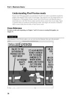
option from the Swatches popup menu. Figure 7.1 shows the default view of the Swatches panel.
FIGURE 7.1
The Swatches panel allows you to select and apply various swatch patterns.
Swatch Libraries menu
Show Swatch Kinds menu
Swatch Options New Color Group
New Swatch
Delete Swatch
Using the color swatches
You can create a new swatch based on the current paint style, which appears in the Paint Style sec-
tion of the Tools panel, by clicking the New Swatch button along the bottom of the Swatches
panel. If you press Alt (Option) when creating a new swatch, the New Swatch dialog box, as
shown in Figure 7.2, opens. This dialog box allows you to initially name the swatch and set its
color mode to either process color (CMYK) or spot color. Process colors are printed using a combi-
nation of the four standard printing inks — cyan, magenta, yellow, and black. Spot colors are
printed using a special premixed ink that’s exactly the color you want to print.
Under the Color Mode in the New Swatch dialog box, you can set Grayscale, RGB, HSB, CMYK, Lab,
or Web Safe RGB. Most default process color swatches are set up with RGB. You can also create
10_345191-ch07.indd 22210_345191-ch07.indd 222 10/24/08 11:26:12 AM10/24/08 11:26:12 AM
223
Understanding Color, Gradients, and Mesh
7
a new swatch by choosing New Swatch from the Swatches panel’s popup menu, which you access by
clicking the triangle on the upper-right corner of the panel.
FIGURE 7.2
The New Swatch dialog box lets you name the new swatch.
Double-clicking a swatch displays the Swatch Options for that swatch. The Swatch Options dialog
box is exactly like the New Swatch dialog box, except that it includes a Preview check box. The
Swatch Options dialog box has the following options:
Swatch Name: Lets you change the name of the swatch, which you can view only in List
view mode
Color Type: Allows you to set the color type of the swatch to either process or spot
Global: Specifies that the changes should be applied throughout the document
Color Mode: Lets you change the mode to Grayscale, RGB, HSB, CMYK, Lab, or Web
Safe RGB
CROSS-REF
CROSS-REF
For more on Web-safe colors, see Chapter 19.
In addition, you can select one or more swatches to edit, duplicate, or remove from the Swatches
panel. Click a swatch to select it; a frame appears on the selected swatch.
You can select more than one swatch by pressing Ctrl (Ô) and clicking additional swatches. If you
press Shift and click additional swatches, a contiguous (connected) set of swatches is selected from
where you initially clicked to where you Shift+clicked. You can deselect individual swatches by
10_345191-ch07.indd 22310_345191-ch07.indd 223 10/24/08 11:26:13 AM10/24/08 11:26:13 AM
224
Illustrator Basics
Part I
pressing Ctrl (Ô) and then clicking selected swatches. You deselect all the swatches by clicking an
empty area of the Swatches panel. By selecting multiple swatches, you can duplicate and delete
several swatches at once.
If you want to sort the swatches manually, you can do so by selecting any number of swatches and
then dragging them to a new location within the Swatches panel.
Using the Swatches popup menu
The Swatches popup menu, shown in Figure 7.3, also has other functions, some of which were
already mentioned:
New Swatch: This option works the same as the New Swatch button at the bottom of the
Swatches panel. A new swatch is created from whatever you select.
New Color Group: This option creates a new color group at the bottom of the swatches
panel (color groups are indicated by a folder on the left side of them).
Duplicate Swatch: This option duplicates the selected swatches. You can also drag a
selected swatch to the New Swatch button (the little piece of paper) to duplicate the swatch.
If you press Alt (Option) while duplicating a swatch, the New Swatch dialog box opens.
Merge Swatches: This option merges two or more selected swatches by using the first
selected swatch’s name and color. You must have two or more swatches selected to
enable this option. It produces a new swatch that’s a mixture of the selected swatches.
Delete Swatch: To delete a swatch, select this option. You can also select the swatch and
then click the trash icon. A warning dialog box appears asking whether you want to
delete the swatch selection. Click Yes to delete the swatch.
Ungroup Color Group: This option ungroups the selected color group.
Select All Unused: This option selects the swatches in the Swatches panel that you aren’t
using in the current document. You can then delete those swatches if desired.
Add Used Colors: This option adds a swatch for each color in your document. You don’t
need to select artwork in order for this to work; selecting this option simply adds a num-
ber of swatches equal to the different colors in your document.
TIP
TIP
Use Add Used Colors in conjunction with New Color Group to quickly create a set
of colors that are used in your document. For this to work, you need to select the
swatches that were just created prior to choosing the New Color Group option.
Sort by Name: This option organizes the swatches (regardless of which viewing mode
the swatch panel is in) alphabetically.
Sort by Kind: This option sorts the swatches to appear, starting with color, then gradi-
ents, and then patterns.
Show Find Field: This option opens a Find field so you can type a specific swatch name
to search for in the Swatches panel.
10_345191-ch07.indd 22410_345191-ch07.indd 224 10/24/08 11:26:16 AM10/24/08 11:26:16 AM