Mastering Autodesk 3ds Max Design 2011 phần 3 pdf
Bạn đang xem bản rút gọn của tài liệu. Xem và tải ngay bản đầy đủ của tài liệu tại đây (4.17 MB, 97 trang )
IntroduCInG the other sPlIne tYPes
|
169
Spline Name
and Function Creation Method
Creation
Options* Parameters*
Ellipse—Draws
ellipses
Click first tangent edge and
drag for other edge [Edge]. Or
click center and drag for edge
[Center].
Edge/Center Length, Width.
Donut—Draws a
donut shape: two
concentric circles
Click first point on circum-
ference and drag for second
point on circumference; click
for second radius [Edge].
Or click center and drag for
first radius; click for second
radius [Center].
Edge/Center Radius 1, Radius 2.
Star—Draws star
shape
Click center and drag for first
radius; click again for second
radius.
Radius 1, Radius 2,
[number of] Points [of star],
Distortion [twist], Fillet
Radius 1, Fillet Radius 2.
Helix—Draws a 3D
helix (spiral)
Click first circumference
point, drag second circum-
ference point, click height,
click second radius [Edge].
Or click center, drag first
radius, click height, and click
second radius [Center].
Edge/Center Radius 1, Radius 2,
Height, Turns, Bias,
CW [clockwise]/CCW
[counterclockwise].
*Items separated by a slash (/) denote radio button options. Italics denote button group names.
You may want to experiment by creating some different splines in a separate file. Remember
that you can extrude most of them into the third dimension by using the Extrude or Bevel modi-
fiers and the Loft compound object, which extrudes a shape along a spline path (you’ll learn
about lofting in Chapter 7, “Organizing and Editing Objects”).
Common parameters among all of the shape primitives are found in the Rendering and
Interpolation rollouts. In the Rendering rollout, you can force 3ds Max to render a two-dimen-
sional spline as if it were a three-dimensional object complete with surfaces. The Interpolation
rollout contains controls for adjusting the number of steps, or straight segments, between each
vertex. The more steps a shape has, the smoother the curves are, but this results in a more com-
plex object when the shape is lofted or extruded.
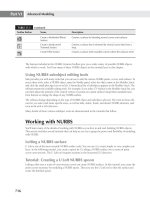
In addition to the Splines group of objects that are created from the Shapes tool, there are
also NURBS curves and a small library of newer shapes called Extended Splines consisting
of common structural steel cross sections. The NURBS Curves and Extended Splines options
are accessed from the drop-down list above the Object Type rollout when the Shapes button is
active. Table 3.3 discusses the Extended Spline types and options.
Table 3.2: Creation Methods for Splines (CONTINUED)
170
|
CHAPTER 3 CreatInG shaPes wIth sPlInes
Table 3.3: Creation Methods for Extended Splines
Spline Name
and Function Creation Method
Creation
Options* Parameters*
WRectangle—Draws
offset rectangular
splines with or with-
out corner radii
Click first corner and drag for
other corner; then click for
inner offset [Edge]. Or click
center and drag for corner,
and then click for inner offset
[Center]
Edge/Center Length, Width, Thickness,
Sync Corner Fillets, Corner
Radius 1, Corner Radius 2.
Angle—Draws an “L”
shape
Click first corner and drag for
other corner; then click for
inner offset [Edge]. Or click
center and drag for corner,
and then click for inner offset
[Center]
Edge/Center Length, Width, Thickness,
Sync Corner Fillets, Corner
Radius 1, Corner Radius 2,
Edge Radii.
Wide Flange—Draws
an “I” shape
Click first corner and drag for
other corner; then click for
inner offset [Edge]. Or click
center and drag for corner;
then click for inner offset
[Center]
Edge/Center Length, Width, Thickness,
Corner Radius.
Channel—Draws a
“C” shape
Click first corner and drag for
other corner; then click for
inner offset [Edge]. Or click
center and drag for corner,
and then click for inner offset
[Center]
Edge/Center Length, Width, Thickness,
Sync Corner Fillets, Corner
Radius 1, Corner Radius 2.
Tee—Draws a “T”
shape
Click first corner and drag for
other corner; then click for
inner offset [Edge]. Or click
center and drag for corner;
then click for inner offset
[Center]
Edge/Center Length, Width, Thickness,
Corner Radius.
*Items separated by a slash (/) denote radio button options.
Editing Splines
You’ve seen how you can edit the rectangle and line through the Modify tab of the Command
panel. In most cases, you need to select the Edit Spline modifier from the Modifier List drop-
down to gain access to the sub-object levels of a spline where parametric controls are usually
shown.
edItInG sPlInes
|
171
The exception to this is the Line spline, which will display its sub-object level options as soon
as you select the Modify tab.
Once you’ve selected Edit Spline, you can make changes to the vertices, segments, or splines
by entering the corresponding sub-object level of the Edit Spline modifier. You can even attach
or detach components of a spline to create new forms, as you’ll see in the next chapter.
Another way to access a spline’s sub-object level is to convert it into an editable spline. This is
accomplished by right-clicking the object name in the modifier stack and selecting Convert To:
Editable Spline from the context menu.
You can also right-click the object in the viewport and choose Convert to Convert to
Editable Spline from the quad menu.
This exposes the sub-object level of the selected spline in a way similar to the Edit Spline
modifier, but it does so by permanently converting the spline to an editable spline. The spline
then loses its parametric functions.
After modifying a spline’s sub-objects using the Edit Spline modifier, especially if vertices
are added or removed, editing the spline at its top level may yield unpredictable results. For this
reason, converting a parametric shape into an editable spline is often preferred over using the
Edit Spline modifier. If you want to experiment with the spline’s sub-objects but are not sure if
the end result will be adequate, use the Edit Spline modifier first. If the desired shape is created,
convert the object into an editable spline. If not, simply delete the modifier to return the shape to
its unaltered configuration.
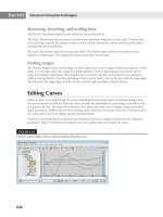
In this chapter, you have learned how to draw splines with the traditional tools in 3ds Max
Design 2011. The Graphite Modeling Tools provide some alternate ways to sketch splines that
can be used for many purposes. For example, you can use the Polydraw panel to sketch splines
on grids or on the topology of other Edit Poly objects that can automatically create polygons
when you create quadrilaterals with the splines you draw.
172
|
CHAPTER 3 CreatInG shaPes wIth sPlInes
Collapsing to an Editable Spline Reduces Memory Usage
Collapsing a spline with modifiers to an editable spline helps reduce the memory usage for your
scene. 3ds Max must use additional memory from your system in order to maintain the parameters
of objects as well as the modifiers in the stack. If you convert a spline to an editable spline, 3ds Max
no longer needs to draw on that additional memory for the spline. As your scene becomes larger,
these memory issues become more important. On the other hand, using the Edit Spline modifier
consumes more memory than converting a primitive spline shape to an editable spline, but you
have the best of both worlds—parametric and explicit control.
Placing and Beveling Text
3ds Max treats text as a parametric spline with parameters that control many features found in
word processing software. Text can be justified, bold, and italicized; the space between letters
can be adjusted (kerned); the space between lines can be adjusted (leaded); and the 3ds Max
text object can use any Windows fonts. 3ds Max is far from a robust text editor, but you will find
most of the tools necessary to add text-based geometry to your scenes, including cutting and
pasting text from TXT files into the Text tool’s Text field.
You’ve noticed that, when you create objects, they are created on and oriented to either
the home grid or a user grid. 3ds Max also has the ability to create grids on the fly using the
surfaces of scene geometry as the basis for the grid’s location and orientation. This feature is
accessed by checking the AutoGrid check box in the Object Type rollout. AutoGrid is available
whenever you create any type of geometry or shape primitive and remains active until the box
is unchecked.
The following exercises explain the use of Text, AutoGrid, and the Bevel modifier:
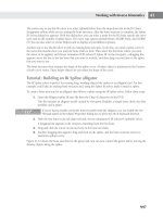
1. Choose File Open and open the Signage.max file from the book’s companion web
page. The file consists of a rectangular sign with a curved border, as shown in Figure 3.85.
The sign has been rotated off the home grid.
2. Click Create Shapes Splines in the Command panel.
Figure 3.85
The rectangular
sign from the
Signage.max file
PlaCInG and beVelInG text
|
173
3. Click the Text button in the Object Type rollout and then select the AutoGrid check box.
4. Drag your cursor over the sign in the viewport and notice that the axis tripod orients its
axes to whichever face the cursor is over at any given time, as shown in Figure 3.86.
5. With the cursor over the central part of the sign, click the mouse to place the default
“MAX Text” text in the scene and on top of the sign. The text is created, but it is too large
for the sign (see Figure 3.87). Uncheck AutoGrid.
The Start New Shape Option
You may have noticed the Start New Shape option near the top of the Splines Object Type rollout.
When this option is unchecked, each shape created becomes a spline sub-object of a greater spline
object, rather than individual, parametric spline objects. This option is checked by default.
6. In the Parameters rollout, select a font from the drop-down list and then adjust the Size
value to change the text to a more appropriate size. Select the text in the Text field and
replace it with the words that you want to appear on your sign.
Figure 3.86
With the AutoGrid
feature active, the
axis tripod orients
itself to the face
over which the
cursor is placed.
Figure 3.87
Placing new text
on the board with
AutoGrid turned on
174
|
CHAPTER 3 CreatInG shaPes wIth sPlInes
Different fonts can yield different results when modifiers are applied to them. This is
usually the result of using a font with tight corners or thin areas, and then beveling the
text in such a manner that it is forced to cross over itself. In other cases the fonts are
designed poorly and don’t work well when extruded or beveled. This exercise uses the
Book Antiqua Bold font with a Size parameter set to 2´3˝.
Cycling Through the Font Options
With the font highlighted in the Parameters rollout, use the up and down arrow keys to cycle through
the fonts and observe how each looks in the viewports. If you use the arrows in the numeric keypad,
make sure Num Lock is not turned on.
The text assumes the characteristics that you assigned, but its location on the sign is too low.
To move it properly, you must use the Local Reference Coordinate System, which uses the X-, Y-,
and Z-orientation of the selected object rather than using the World Coordinate System.
1. Click the Select and Move button on the Main Toolbar.
2. To the right of the transform tools, expand the Reference Coordinate System drop-down
list and select Local as shown in Figure 3.88.
3. Select the text and notice that the Move Transform gizmo is oriented to the text. Place the
cursor over the XY-plane handle and move the text into place, as shown in Figure 3.89.
Most real-world objects that you will find outside of a machine shop do not have perpendicu-
lar faces that join at sharp angles. They usually have a curved (filleted) or straight (chamfered)
transition between the surfaces. Although it may not be obvious visually, this transition in your
scene will appear more realistic to the viewers by creating a condition that they are used to
seeing. With proper lighting, the transition surfaces can generate a specular highlight, subtly
Figure 3.88
Choose the Local
coordinate system
Figure 3.89
Moving the text
into place
PlaCInG and beVelInG text
|
175
calling attention to the condition. The Extrude modifier does not provide for a fillet or chamfer,
but these features can be found in the Bevel modifier’s option, as explained in the following
steps. Although this example uses text, the Bevel modifier can be used with any spline.
The Bevel modifier’s Bevel Values group has controls for setting the height and outline
amount at three different locations perpendicular to the spline’s current location. The Outline
value is an offset size that the shape assumes, at the specified Height value, relative to its origi-
nal size.
Add the Bevel modifier to your text using the following steps:
1. Select the text, click the Modify tab, and then choose Bevel from the Modifier List
drop-down.
2. In the Bevel Values rollout, set the Level 1 Height parameter to 3˝ and leave Outline set
to 0.0˝. This will generate an initial straight segment for the letters.
3. Check the Level 2 check box. Set the Level 2 Height to 0.25˝ and the Outline to -0.25˝.
4. Zoom into the letters to see the chamfered effect of the Bevel modifier, as shown in
Figure 3.90.
5. In the Parameters rollout, select Curved Sides in the Surface group, set Segments to 4, and
select the Smooth Across Levels check box. These settings will generally soften the transi-
tion between levels and, when a small Outline value is present, can create a ridge around
the perimeter of the splines, as shown in Figure 3.91.
Figure 3.90
The chamfered
effect of the Bevel
modifier
Figure 3.91
Smoothing
the transition
between surfaces
176
|
CHAPTER 3 CreatInG shaPes wIth sPlInes
The Bottom Line
Draw shapes with splines Two-dimensional splines can be used as the building blocks for
more complex, three-dimensional objects. You can draw splines from scratch using the Line
tool or start with a parametric shape and then collapse it to an editable spline.
Master It Create a rainbow-shaped set of splines—in other words, a series of concen-
tric arcs.
Outline and extrude splines Outlining splines provides a way to create a new spline sub-
object that parallels the original. This is faster and more accurate than creating the second
spline manually and then attaching it to the original. Extruding splines is the most common
method for creating 3D objects from 2D splines.
Master It A column surround is a shell that covers a structural column to give it a more
appealing appearance. Create a 16´-tall, 2˝-thick, semicircular column surround with a 16´
outside radius.
Modify closed splines with Boolean tools Nearly any shape can be formed using the
standard Editable Spline two or more simple shapes and combine them for a more complex
shape.
Master It Using the spline Boolean tools, create the cross-sectional shape of a fluted
column, similar to the shape shown here.
Chapter 4
Editing Meshes and Creating
Complex Objects
In the three previous chapters, you spent some time becoming familiar with 3ds Max. In this
chapter, you’ll continue exploring 3ds Max’s features while exercising your newfound skills.
You’ll start by learning how to add openings to the walls you created in Chapter 3, “Creating
Shapes with Splines.” Then you’ll learn how you can import scanned images that you can use to
trace. In the process of tracing a floor plan, you’ll further explore methods for creating and edit-
ing forms using splines. You’ll also be introduced to ways you can edit the extruded shapes that
you have created, as well as edit any other mesh object. In this chapter, you’ll learn to:
Create openings with ProBoolean operations
•u
Designate a modeling template image•u
Create and modify objects using box modeling•u
Attach objects to a mesh•u
Create clones with Array and Snapshot•u
Creating Openings in a Wall with Boolean Operations
In Chapter 3, you created a set of walls that completely enclosed a space. Now you need to add
wall openings between the enclosed spaces of your model. To do this, you’ll use Boolean opera-
tions to remove portions of a wall.
A Brief History of Booleans
Boolean operations are named after George Boole, who developed a mathematical branch of sym-
bolic logic. Boolean logic includes AND, OR, and NOT operators, which correspond to geometric
union, intersection, and subtraction.
Boolean operations are methods you can use to join two objects, subtract the shape of one
object from another, or obtain a shape that is the intersection of two objects. Figure 4.1 illustrates
the effect of Boolean operations on some sample shapes.
178
|
CHAPTER 4 edItInG Meshes and CreatInG CoMPlex objeCts
3ds Max allows you to use two existing objects to form one new object using Boolean opera-
tions. The original objects are referred to as the operands of the Boolean operations, and they are
not deleted when the operation is performed; they become sub-objects of the resultant Boolean
object. In the following exercise, you’ll use a simple box to define the opening in your walls. The
existing wall is one operand, and the box that forms the opening is the other operand.
3ds Max now has the ProBoolean and ProCutter compound objects. The ProBoolean com-
pound object has the classic three Boolean operations and adds Merge, Attach, and Insert. You
can also use the Imprint and Cookie Cutter options to further enhance your operations. The
ProBoolean tools keep the history of operations; you can modify the operators or change the
ordering of operators anytime you want. You can even change an operation’s type (for example,
change a subtracted operand to a union operand). The ProBoolean operations create better
geometry than the original Boolean tools in 3ds Max. They provide you enormous flexibility in
creating objects for your visualizations.
Hiding Shapes That Get in the Way
Start by setting up your wall model and creating an object you’ll use to subtract from the walls.
1. Open the My_Walls.max model you created in the previous chapter, or open MyWalls04
.max that you downloaded from www.sybex.com/go/mastering3dsmaxdesign2011.
2. If your 3ds Max window shows only a single viewport, click the Maximize Viewport
Toggle to view the four viewports.
You’ll need to hide the ceiling of your model in order to more easily work on the model.
Here’s a quick way to temporarily hide objects if they’re in your way.
Figure 4.1
Examples of Bool-
ean operations
Box
Box subtract star
Star
Box intersect star
Box union star
Outline of
box and star
shown for
clarity
CreatInG oPenInGs In a wall wIth boolean oPeratIons
|
179
3. Right-click in the viewport, choose Select from the quad menu, and then click to select
the ceiling.
4. Click in the Name input box in the Name and Color rollout in the Command panel and
change the name to Ceiling, as shown in Figure 4.2. This will help you find the ceiling later.
5. Right-click in the viewport and choose Hide Selection from the quad menu (see
Figure 4.3). The ceiling disappears.
6. The ceiling hasn’t really gone anywhere—you’ve just hidden it. Just so you know where
to look when you do need to turn it back on, right-click again and choose Unhide by
Name from the quad menu, as shown in Figure 4.4.
The Unhide Objects dialog box appears, as shown in Figure 4.5.
7. You can see that Ceiling is listed in the dialog box. To turn it back on, you would click the
name in the list and then click Unhide. You want to keep it off for now, so click Cancel.
The display functions shown in this section are also available from the Display tab of the
Command panel and by selecting Tools Display Floater.
Figure 4.2
Rename an object in
the Command panel.
Figure 4.3
Using the quad
menu, hide the
selected object.
Figure 4.4
Unhide the
selected object.
Figure 4.5
The Unhide Objects
dialog box
180
|
CHAPTER 4 edItInG Meshes and CreatInG CoMPlex objeCts
Creating the Shape of the Opening
Now you’re ready to get to work on the walls. Your first step is to create the shape of the open-
ing. You can think of this shape as the negative space of the opening or as the shape that is to be
removed from the wall.
1. Click in the Top viewport to make it active.
2. Click the Zoom Extents tool so that you can see the entire plan in the viewport.
3. Click the Geometry tool in the Create tab of the Command panel and make sure Standard
Primitives is selected in the drop-down list.
4. Click the Box button in the Object Type rollout. Then, in the Top viewport, click and
drag a rectangle that is roughly 3´ × 3´ square to the location shown in Figure 4.6. You
don’t need to draw the box precisely, because you’ll enter the exact dimensions in the
Parameters rollout.
5. Make the height of the box roughly 7´.
6. Go to the Parameters rollout of the Create tab and set the Length and Width values to 3´
and Height to 6´8˝.
You now have a box that will be used to create an opening. The next steps are to place the
box in the locations for the openings.
7. Click the Select and Move tool in the Main Toolbar and move the box to the location
on the left, as shown in Figure 4.7. Remember that you need to place the cursor on the
selected object. Then, when you see the Move cursor, click and drag the object into
position.
8. Shift+click and drag the box to make a copy of the box in the location to the right, as
shown in Figure 4.7.
9. In the Clone Options dialog box, click Copy and then click OK.
Figure 4.6
Placing the box
in the plan
CreatInG oPenInGs In a wall wIth boolean oPeratIons
|
181
Subtracting the Opening from the Wall
Now that you have the object ready, you can use the ProBoolean tool to subtract it from the wall.
First, you’ll select the object from which you want to subtract the opening—this is referred to as
Operand 0. Afterward, you’ll select the object to subtract, called Operand 1.
1. Click the Select Object tool and click the first wall you created, as shown in Figure 4.8.
2. Click the drop-down list under the row of tools near the top of the Command panel, and
then select Compound Objects as shown in Figure 4.9.
3. Click the ProBoolean button in the Object Type rollout. The ProBoolean options appear in
the Command panel.
Figure 4.7
Positioning the
boxes in the door-
way locations
Move the box here. Make a copy here.
Figure 4.8
Selecting the wall
for the Boolean
operation
Operand 1; select
this object second.
Operand 0; select
this object first.
Figure 4.9
Starting the cre-
ation process for
compound objects
182
|
CHAPTER 4 edItInG Meshes and CreatInG CoMPlex objeCts
4. Scroll down the Command panel to the Parameters rollout and make sure that the
Subtraction radio button is selected (Figure 4.10).
5. Click the Start Picking button in the Pick Boolean rollout.
6. Click the box that intersects the wall, as shown in Figure 4.8.
If you look in the Perspective viewport, you’ll see that an opening appears in the wall where
you located the box, as shown in Figure 4.11.
ProBooleans Are More Powerful Than Booleans
You may have noticed the Boolean option under the Object Type rollout. This is the older Boolean
tool developed with 3ds Max. This tool is at least 15 years old; it was part of the first release of 3ds
Max in 1995. ProBoolean was a more powerful plug-in available for 3ds Max that has been incor-
porated into the program.
Now repeat the operation for the other wall:
1. Click the Select Object button to exit the ProBoolean tool and then click the second wall,
as shown in Figure 4.12.
This becomes the first operand for the next Boolean operation.
2. Click the ProBoolean button in the Object Type rollout of the Command panel.
3. Click the Start Picking button, and then select the box, as shown in Figure 4.12. The sec-
ond opening appears, as shown in Figure 4.13. You may need to Orbit your viewport a
little to get a better view of the new opening.
Figure 4.10
Choose the Boolean
operation to be
performed.
Figure 4.11
The opening in
the wall
CreatInG oPenInGs In a wall wIth boolean oPeratIons
|
183
In this example, you created a simple rectangular opening in the wall. The shape of the open-
ing can be anything you want it to be. You just need to create the geometry, using primitives or
extruded splines. In addition, the object that you’re subtracting from doesn’t need to be thin like
the wall in this example. It can be any geometry you want, and the subtracted shape will leave
its impression. Figure 4.14 shows some examples of other Boolean subtractions to give you an
idea of other possibilities.
Figure 4.12
Selecting the wall
and box for the
second opening
Select the box second.Select the wall object first.
Figure 4.13
The Perspective
viewport showing
the second opening
Figure 4.14
Some samples of Bool-
ean subtractions
184
|
CHAPTER 4 edItInG Meshes and CreatInG CoMPlex objeCts
Creating Multiple Openings in a Single Wall
You can perform multiple ProBoolean operations on any 3D object, such as creating several
openings in one wall. To do this, you only need to continue selecting objects while the Start
Picking button is selected. All of the objects selected become operands of the Boolean operation.
If you’ve deselected a ProBoolean object, simply reselect it, click the Modify tab, click the
Start Picking button, and then continue picking operands. If you have a number of objects to
subtract from another, after you have clicked the Start Picking button, you can press the H key
on the keyboard to bring up the Select from Scene dialog box and select all of the objects for
your operation. All of the objects will appear in the Operands display; they can still be reor-
dered and modified as if you had selected them individually.
If you collapse a ProBoolean object to an Editable Mesh or Editable Poly you lose the oper-
ands history. This means you cannot edit the openings by going back and changing the size of
the boxes. You can, however, edit openings in the object at sub-object levels.
Making Changes to the Opening
Suppose that you decide to increase the size of one of the openings. You can go back and
modify the box used as the Boolean operand so that it’s wider. This, in turn, will increase
the opening size.
1. Click the Select Object tool in the Main Toolbar and click the first wall, as shown in
Figure 4.15.
2. Click the Modify tab in the Command panel. Scroll down to the Display section of
the Parameters rollout and click the Operands radio button. The box reappears in the
viewports.
3. Scroll down to the bottom of the Parameters rollout, and then click the 1: Subtr – Box001
item in the selection field. See Figure 4.16.
Figure 4.15
Moving the oper-
and to change the
location of the wall
opening
Resize operand and move to this location.
Select this wall.
Figure 4.16
Selecting the sub-
traction operation
CreatInG oPenInGs In a wall wIth boolean oPeratIons
|
185
4. Notice that Box is now listed in the modifier stack at the top of the Command panel. Click
the Box item. See Figure 4.17.
The Command panel options change to show the parameters for the box.
5. In the Parameters rollout, change the Width value to 6´. Notice how the box changes in the
viewports as you edit the Width parameter.
6. Go back to the top of the modifier stack and select ProBoolean.
7. Scroll down to the Parameters rollout and click the Result radio button, shown in
Figure 4.18.
Now you can see the result of your edit in the Perspective viewport. The opening is now
6´ wide instead of 3´ wide.
Besides altering the shape of the box, you can also reposition it to change the location of the
opening in the wall. Here’s how it’s done:
1. Click the Operands radio button in the Parameters rollout again to view the box.
2. Scroll up the Command panel to the modifier stack and click the plus (+) sign next to the
ProBoolean option, and then click the Operands entry. It highlights to indicate that it is
selected. See Figure 4.19.
3. Click the Select and Move tool in the Main Toolbar. Then click and drag the box to the
left, in the -X direction, so that it passes through the corner of the wall, as shown earlier
in Figure 4.15.
4. Click Operands again in the modifier stack, or click the top ProBoolean entry to exit the
sub-object level (the yellow color disappears).
Figure 4.17
Selecting the Box
in the stack
Figure 4.18
Display the result.
Figure 4.19
Selecting the Oper-
ands sub-object
186
|
CHAPTER 4 edItInG Meshes and CreatInG CoMPlex objeCts
5. Scroll down the Parameters rollout and click the Result radio button. The new wall open-
ing configuration appears in the Perspective viewport, as shown in Figure 4.20.
6. Save the Mywalls04.max file incrementally by choosing File Save As and clicking the
plus (+) button in the Save File As dialog box. The file will be named My_Walls01.max if
you continued from the previous chapter or Mywalls05.max if you used the file provided.
The tricky part of moving the opening in this exercise is making sure that the sub-object
level is active and that the proper operand is selected at the bottom of the Parameters rollout.
These exercises demonstrate that you can alter the shape of the opening by modifying the
parameters of the object you used to create the opening. The trick here is to know how to get to
the box operand in order to edit its parameters. It’s a good idea to first make the subtracted oper-
and visible. It’s not absolutely necessary, but it helps to see the operand as you make changes.
Use the modifier stack to gain access to the operand. Once there, you can access the operand’s
parameters and make changes to its geometry or change its location. To change the location of
either of the operands within a compound object, go to the Operands sub-object level and select
the operand. The operands are considered sub-objects of the ProBoolean compound object. Like
almost everything else in 3ds Max, this can be animated. You can use ProBoolean animations to
make quick animations of objects appearing or disappearing.
Tracing a Sketch
You cannot always predict when or where you’ll have a brilliant design idea. Frequently, ideas
arise when you’re sitting at a table during a brainstorming session or perhaps even while you
are out eating lunch. The basic tools of pencil and paper offer the spontaneity needed to express
your ideas freely.
Once you’ve created an inspired sketch, 3ds Max offers a way to quickly transfer your inspi-
ration into a 3D model. Among its view options, 3ds Max supplies a tool that displays a bitmap
image in the viewports for a variety of purposes, including the tracing of scanned design
sketches.
In this section, you’ll continue your exploration of splines by importing a sketch and tracing
it. You’ll use a sketch that roughly approximates the floor plan of Notre Dame du Haut, more
commonly known as the Chapel at Ronchamp, which was designed by Le Corbusier in 1950.
Figure 4.20
The result of moving
the box operand
traCInG a sKetCh
|
187
Figure 4.21 shows a photograph of one view of the famous building. If you use Google to search
for images of the Ronchamp Chapel you’ll find hundreds of photos that give views of all sides of
this masterpiece of modern architecture.
By modeling this building, you will have the opportunity to examine how you might use
splines to create shapes other than simple straight walls like those you created in the previous
chapter. You’ll also be introduced to other methods for modeling forms by combining splines
and primitives.
Ensuring Your Bitmaps Appear Correctly
Depending on your installation, bitmaps used as template images may appear pixelated and be
unusable. To ensure they look their best, before you start the next exercise, save your file and then
choose Customize Preferences Viewports Configure Driver. In the Appearance Preferences
Group, under Download Texture Size, select the highest resolution size listed and check the Match
Bitmap Size as Closely as Possible option. Next, click OK, exit and restart 3ds Max, and then con-
tinue with the next exercise.
Using a Bitmap Image
Using a bitmap image as a modeling template is fairly simple, but you need to watch out for a
few settings. In the following exercise, you’ll import an image that is a sketch of the Ronchamp
Chapel floor plan. The sketch shows a grid that is spaced at approximately 4.5 meters, as shown
in Figure 4.22.
Figure 4.21
Notre Dame du
Haut in Ronchamp
188
|
CHAPTER 4 edItInG Meshes and CreatInG CoMPlex objeCts
You will apply this image onto a plane object, so first set up 3ds Max so that you can see only
the maximized Top viewport.
Accessing the Background Image
To access the background image, you’ll need a file from this book’s website (www.sybex.com/go/
mastering3dsmaxdesign2011), so make sure you’ve installed the sample files before you start.
1. Choose File Reset, and click Yes at the reset query message.
2. Click the Create tab of the Command panel, and click the Plane button.
3. Press Alt+W to display four viewports, and then activate the Top viewport. Press Alt+W
again to display the Top viewport as a single view. Now draw a plane that is about 20´ × 20´,
and deselect the Real-World Map Size check box at the bottom of the rollout, as shown in
Figure 4.23.
Figure 4.22
The bitmap image
of the Notre Dame
du Haut floor plan
Figure 4.23
Creating the
image plane
traCInG a sKetCh
|
189
4. With the Plane001 object selected, right-click the Select and Move icon on the Main
Toolbar to open the Move Transform Type-In box.
5. Enter 0 for both the X and Y locations, and press Enter to center the plane on the world
origin, as shown in Figure 4.24.
Now you’re ready to set up your scanned floor plan.
6. Click the Material Editor icon on the Main Toolbar to open the Material Editor, shown
in Figure 4.25. Note there are now two different Material Editors in 3ds Max; here we’re
using the Compact Material Editor. The icon on the Main Toolbar is a flyout now, so make
sure you’ve chosen the correct one. The icon should look like the one in the margin here.
The Material Editor uses the renderer to display the sample spheres. If the sample spheres
display as black holes, you’ll need to change the renderer to the mental ray renderer.
Choose Rendering Render Setup, close the Common Parameters rollout, and open
the Assign Renderer rollout. Locate the Production Renderer field, and click the Choose
Renderer button, marked with three dots. Choose the mental ray renderer and click OK.
The Material Editor should now display the sample spheres correctly.
Figure 4.24
Centering the
plane on the
world origin
Figure 4.25
The Material Editor
190
|
CHAPTER 4 edItInG Meshes and CreatInG CoMPlex objeCts
You will be using the Material Editor here to set up your sketch to use as a modeling
template. The Material Editor will be covered in more detail in Chapter 9, “Enhancing
Models with Materials.”
7. Pick the second sphere in the upper-left corner of the material samples. The thick, white
border around the sample will indicate that it is selected.
8. Click in the Material Name box and rename 02 – Default to RonchampPlan so that you
will know where you will use the material. Click the button to the right of the material
name currently labeled Arch & Design to change the material type. In the Material/Map
Browser’s Materials rollout, click Architectural in the Standard materials and then click
OK. This should change the material type to Architectural for the new material you are
making. Note that changing the material type changes the available parameters and roll-
outs for the new material.
9. In the Physical Qualities rollout, click the button currently labeled None to the right of
the Diffuse Map item. This will again bring up the Material/Map Browser.
10. To open the Select Bitmap Image File dialog, open Standard in the Maps rollout, and
double-click the Bitmap entry at the top of the listing of available maps.
11. Navigate to where you downloaded the ronchampscan.gif file, select the file, and click
the Open button.
12. In the Coordinates rollout, which is now visible in the Material Editor, deselect the Use
Real-World Scale option. This causes the Width and Height fields to change to U and V.
13. Change the Tiling value for both U and V mapping coordinates to 1, and deselect the
Tiling option for both. Click the Go To Parent button to go to the top level of the material
you just created. Leave the Material Editor open.
14. Select the Plane001 object you created at the beginning of these exercises, and in the
Name and Color field, rename the Plane to RonchampPlanTemplate so that you will be
able to identify the object in the scene in the future.
15. With the RonchampPlanTemplate object selected, click the Assign Material to Selection
button.
16. Click the Show Standard Map in Viewport button. The scanned image appears on the
plane object in the Perspective viewport, as shown in Figure 4.26.
Figure 4.26
The Ronchamp
image plane in
the Perspective
viewport
traCInG a sKetCh
|
191
How Resetting 3ds Max Differs from Starting a New File
The difference between choosing File Reset and choosing File New is subtle, but there is an
important distinction. When you reset the scene, you are starting completely over and everything
defaults to the way it was when you first launched 3ds Max. When you create a new scene, it merely
erases all the objects, leaving your scene seemingly empty; however, the new scene still has all the
materials, units, and other settings as they were set before you chose File New.
Scaling the Image Plane to the Model’s Size
The image appears stretched across the 20´ × 20´ plane that you created at the beginning of the
exercise. You’ll want to size the image plane so that it’s to scale—that is, so that the distances
represented by the image are the same as those in the 3ds Max model. You can approximate the
correct scale, although you won’t be able to get it exactly the same. Here’s how it’s done:
Start by setting up the units with which you’ll be working.
1. Choose Customize Units Setup. The Units Setup dialog box displays (see Figure 4.27).
2. Click the Metric radio button and make sure Meters is displayed in the Metric drop-
down list. Then click OK.
You’ll use meters in this example because this is a European building project. Now let’s
scale the image plane to the proper size.
3. Type G to toggle off the grid display.
If you look at the scanned image carefully, you’ll see a grid whose spacing is about
4.5 meters.
You see 10 reference grid spaces in the horizontal direction. By inspecting the image in an
application such as Photoshop, you can determine that the grid lines are about 63 pixels apart
and that the image is 640
× 470 pixels. You can use these numbers and the grid spacing interval
estimate of 4.5 meters to determine that the entire image is 45.85 meters × 33.57 meters.
Figure 4.27
The Units Setup
dialog box
192
|
CHAPTER 4 edItInG Meshes and CreatInG CoMPlex objeCts
Now you will adjust the size of the image plane to accommodate the measurements of the
sketch.
1. Select the RonchampPlanTemplate object and then click the Modify tab of the Command
panel (see Figure 4.28).
The Length and Width values are now shown in meters.
2. Set the Length value to 33.57 and the Width value to 45.85, based on the image scaling
calculations. Change the image plane’s Length and Width Segments to 4, as shown in
Figure 4.29.
3. Press the G key to turn on the grid.
4. Click the Zoom Extents All button.
5. Press Alt+W to display four viewports if you’re still in a single viewport.
6. Save your scene as MyRonchamp01.max
You will see your modeling template displayed in the Top and Perspective viewports, as
shown in Figure 4.30.
Figure 4.28
The Parameters
rollout for the Ron-
champPlanTem-
plate object
Figure 4.29
Sizing the Image
Plane object
Figure 4.30
The ronchamp-
scan.gif image
applied to your
plane object in the
Top viewport
traCInG a sKetCh
|
193
The RonchampPlanTemplate image plane that you have created may not be exactly the same
size as the real chapel, but based on the estimate of the grid size of the hand-drawn sketch, it is
probably as close as you can make it. If you had accurate dimensions from the actual structure
that related to parts of the sketch, and if you knew the sketch was very accurate, you could get a
much closer approximation of the size of the structure.
When creating 3D objects for visualization, it is crucial that you build all your objects at their
real-world size. Doing so will help you significantly as you build a collection of objects and
buildings that you can merge together to create more visually interesting scenes. If your objects
are not built to real-world size, the objects will not relate to each other, and you will have to
manually scale and guess at the sizes of objects to make them fit together correctly.
There are other reasons for building your objects at their real-world size. The mental ray
materials that you will learn about in Chapter 9 are designed to work in real-world units. If you
use those materials on objects that are not real-world size, the results can be unpredictable. The
photometric lights are also intended to be used in models that are real-world size, and you will
get the best results if your models are built to the correct real-world size.
Avoid Distortion by Using BitMap Fit
There is another way to make sure that the image you apply the plane doesn’t get distorted. Applying
a UVW Map modifier to the plane and choosing Bitmap Fit will lock the proportions of the UVW
coordinates to the original bitmap, avoiding distortion.
Now that you have set the image plane to a size that makes some sense scale-wise, you are
ready to get on with the real work of building the model.
Tracing the Image
To trace the bitmap, you’ll use the Line tool that you were introduced to in the previous chapter.
You won’t trace all of the walls at first.
Start by tracing the small, U-shaped wall on the exterior of the chapel:
1. Continue with the previous exercise or open Ronchamp01.max. If you use the provided
file, you may need to retarget the ronchampscan.gif image in the Material Editor.
2. In the Top viewport, use the Zoom Region tool to zoom into the U-shaped wall area so
that your view looks similar to Figure 4.31. Don’t select too small an area.
Figure 4.31
Tracing the wall
Continue creating points in
a counterclockwise fashion.