Mastering Autodesk 3ds Max Design 2011 phần 6 potx
Bạn đang xem bản rút gọn của tài liệu. Xem và tải ngay bản đầy đủ của tài liệu tại đây (3.96 MB, 97 trang )
460
|
CHAPTER 9 enhanCInG Models wIth MaterIals
Selecting Two-Sided Materials
The 2-Sided option is sometimes needed to correct improper normal orientation in models that
have been imported from other 3D programs, particularly CAD programs. This option isn’t usually
as critical for models built entirely within 3ds Max because the surfaces are usually facing in the
correct direction and single-sided materials generally are sufficient.
6. Click the None button next to the Diffuse Map label, and in the Material/Map Browser
open the Maps group and then the Standard group. Then double-click Bitmap.
7. In the Select Bitmap Image File browser that opens, navigate to the C:\Program Files\
Autodesk\3ds Max Design 2011\maps\ArchMat folder. Your actual folder path may vary.
8. Double-click the Woods&Plastics.FinishCarpentry.Urethane.jpg file to add it to the
Diffuse Map channel of the current material and return to the Material Editor.
9. This time, rather than selecting the destination and clicking the Assign Material to
Selection button, simply click in the material slot and drag it to the floor as shown
in Figure 9.23. A tooltip appears, identifying the object to which the material will be
assigned.
10. Render the scene with the floor material added. It’s difficult to see any change because the
tile pattern isn’t evident.
Try changing the lighting in the scene to see how it affects the materials. Remember that
a surface’s rendered appearance is the result of the combination of its geometry, lighting, and
materials.
Adding Material Mapping Coordinates
If you just want to manipulate the color, transparency, and shininess of an object, you can usu-
ally create or use a material that doesn’t use bitmaps to simulate a texture. Once you start to add
a texture using bitmaps, you’ll need to specify how that texture is applied to the object. You’ll
want to tell 3ds Max the size of the texture in relation to the object, as well as its orientation on
Figure 9.23
Assigning a mate-
rial by dragging it
into the scene
edItInG MaterIals
|
461
the object. For example, you wouldn’t want the brick pattern to appear with its courses running
vertically, as in the example shown in Figure 9.24, nor would you want the brick pattern to be
quite so large.
To control how materials are applied to objects, you’ll want to know how to use the UVW
Map modifier. This modifier lets you precisely control the way a material is placed on an object.
In the next exercise, you’ll add the modifier to the condo floor to establish the orientation and
size of the Floor_Condo_Wood material in relation to the object.
What Does UVW Mean?
The UVW in the name UVW map refers to the coordinates of a material map. They indicate the direc-
tion of a map in a way similar to the XYZ Cartesian coordinates with which you’re already familiar.
The letters UVW differentiate map coordinates from the standard XYZ-coordinate designation and
were chosen simply because they precede XYZ in the alphabet.
UVW map coordinates need to be differentiated from XYZ-coordinates because, although they indi-
cate direction similar to XYZ-coordinates, they are in relation to the length and width of the image
map regardless of the object’s orientation in space. UVW-coordinates also don’t treat measured
distances in the same way. In a Cartesian coordinate system, distances are measured at specific
intervals of feet, meters, or whatever measurement system you’re using. UVW map coordinates,
on the other hand, are measured as a percentage of width and height of a surface. Instead of feet or
meters, UVW maps use real values from 0 to 1. The value used represents a percentage of the overall
width of the surface being mapped, with 1 being equal to 100 percent of the surface width.
Because the coordinate values in a UVW map are based on a percentage, a U value of 0.5 can repre-
sent a measured distance that’s different from a V value of 0.5. For example, imagine a rectangular
surface with a UVW-coordinate system whose origin is the lower-left corner of the rectangle. The
upper-right corner of the rectangle would then be the coordinate 1,1, even though the length and
width of the rectangle are not equal to each other. This may seem a bit odd at first, but if you consider
that material maps are used to match an image to a surface, you begin to see the rationale behind
the UVW map system. The relationship between a map and a surface is more important than their
actual dimensions. You can think in terms of “What percentage of the surface does the map cover?”
rather than “How many square inches does the map cover?”
Figure 9.24
A brick wall with
the brick courses
running vertically
and at a large scale
462
|
CHAPTER 9 enhanCInG Models wIth MaterIals
A UI Discrepancy
Oddly, the modifier in the Modifier List drop-down is named UVW Map although UVW Mapping
appears in the modifier stack.
1. Right-click the Top viewport; then use the Zoom Extents tool to zoom out so that your
view looks similar to Figure 9.25.
2. Click the Select by Name tool and use the Select from Scene dialog box to select the
Floor407 object.
3. Click the Modify tab of the Command panel, expand the Modifier List drop-down, and
then assign the UVW Map modifier to the Floor407 object.
4. In the Parameters rollout, make sure Planar is selected as the mapping type and then
deselect the Use Real-World Map size option at the bottom of the Mapping group.
Turning this option off allows you to manually control the number of times the map
repeats itself.
5. In the Alignment section, click the Fit button to adjust the gizmo size to match the size of
the floor.
Let’s take a moment to study the UVW Map gizmo. It has one green edge and a small line
sticking out on one side. You will have to expand the UVW Mapping modifier and select
the gizmo to see the colors. Figure 9.26 gives you a clear picture of what the gizmo looks
like. If the map is oriented incorrectly, use the Select and Rotate tool to rotate it properly.
The colored edge and the small line help you orient the UVW Mapping gizmo on an
object by showing you which way is up and which directions are left and right: the short
line extending from the frame indicates the top of the image and the green edge denotes
the right side. You’ll get a more detailed look at the UVW Mapping gizmo after the cur-
rent exercise. You can increase the amount of tiling two ways: decrease the size of the
gizmo or increase the Tile values in the Parameters rollout. Let’s continue by adjusting
the Tile values to reduce the size of the material on the Floor407 object.
Figure 9.25
The condo in the
Top viewport
edItInG MaterIals
|
463
If you were to render the scene now, the woods&plastics.finishcarpentry.urethane
.jpg image would be stretched across the floor a single time and appear pixelated. You’ll
want to scale the Floor_Condo_Wood material to a size that’s more in line with the size
of the floor object by instructing 3ds Max to repeat, or tile, the material several times.
Continuing from the previous steps, you will use the UVW Map modifier to improve the
appearance of the floor’s texture map.
6. In the Mapping section, enter 20 in both the U Tile and V Tile input fields. This causes
any material assigned to the floor object to repeat itself 20 times within the boundary of
the UVW Mapping gizmo.
7. Render the scene. The linear pattern of the image map becomes apparent, as shown in
Figure 9.27.
There is one final step that you are going to do to make the floor material pop just a little
more. The Architectural materials’ Intensity parameter controls the brightness of the
material. In the Intensity channel you’ll use the same map that you used in the Diffuse
color channel.
Figure 9.26
The UVW Mapping
gizmo assigned to
the Floor407 object
Figure 9.27
Changing the U
and V Tile settings
causes the diffuse
color map to repeat
over the surface of
the object.
464
|
CHAPTER 9 enhanCInG Models wIth MaterIals
Removing Bitmaps from Materials
There are several methods for removing a map from a material. While the map’s parameters are
visible (the Coordinates and Bitmap Parameters rollouts), you can click the Reset Map/Mtl to Default
Settings button in the Material Editor toolbar and then click Yes in the warning dialog that opens.
Finally, you can click and drag any button labeled None in the Maps rollout and drop it over a button
containing a map name to clear the map slot.
8. Click the Diffuse Map button and drag the map to the Intensity button in the Special
Effects rollout, as shown in Figure 9.28.
9. In the Instance (Copy) Map dialog box that appears, choose Instance, and then click OK.
Using the instance option, changes made to one map are immediately made to the other.
10. Render the scene once more, and you’ll see that the wood strips are more defined.
Exposing All Available Sample Slots
If your Material Editor displays only 6 or 15 samples, don’t worry. You can access the remaining
slots by using the vertical and horizontal scroll bars around the slots, or you can expose all of the
slots at one time. To expose all of the slots, click the Options button on the Material Editor’s vertical
toolbar to open the Material Editor Options dialog box.
Figure 9.28
Dragging a map
from one channel
to another
understandInG MaPPInG CoordInates
|
465
In the Slots area at the bottom of the dialog box, select the 6 × 4 radio button. Click OK to accept the
changes; the Material Editor updates to show all 24 sample slots. There is no practical limit to the
number of materials in a scene—the number of materials is limited only in the Material Editor.
Understanding Mapping Coordinates
The UVW Map modifier you added in the previous exercise told 3ds Max the size, location, and
orientation of the material on the object to which it is assigned. At render time, the image is usu-
ally applied to the object in a repeated, or tiled, fashion. You can also set a material to apply the
bitmap just once. In this section, you’ll take a closer look at the UVW Map modifier.
What Happens When You Add the Mapping Coordinates
The UVW Mapping gizmo you saw in the previous exercise is a visual representation of the
mapping coordinates. Its shape and color are aids in helping you see the bitmap’s orientation
more clearly. As mentioned earlier, the small line at the top of the icon represents the top of the
bitmap, while the green shows the right side. These indicators can tell you at a glance whether
the bitmap image of the material you are using is upside down or backward in relation to the
object to which the coordinates are being applied, as shown in Figure 9.29.
Figure 9.29
The UVW Mapping
gizmo in relation to
a material bitmap
Point
Green edge
The UVW Mapping gizmo
466
|
CHAPTER 9 enhanCInG Models wIth MaterIals
The orientation of the bitmap in the preceding exercise is really not that important, but it can
be important for texture maps that do have a specific orientation, such as a brick pattern, or for a
single image, such as a wine label or a road sign. The UVW Mapping gizmo shows the approxi-
mate size of the bitmap in relation to the object to which it is being applied. When the model is
rendered, multiple copies of the image are applied over the entire surface of the object, like tiles
on a kitchen counter.
Figure 9.30 shows another way that the gizmo affects the appearance of a material. You see a
brick wall with the gizmo rotated. The bricks are angled and aligned with the UVW Mapping
gizmo.
Adjusting the UvW Mapping Gizmo
You have a number of options for controlling the size, shape, and orientation of the UVW
Mapping gizmo. These will be crucial to your ability to place materials accurately on an object
or an individual face. Here are descriptions of the Alignment group options as they appear in
the Command panel:
Manipulate Activates the Select and Manipulate tool. You can also access this tool by
clicking the Select and Manipulate icon on the Main Toolbar. The Manipulate option causes
the gizmo to turn green and a cursor to appear like the Select cursor when it is over the
edges of the UVW Mapping gizmo. Using the Select and Manipulate transform, you can click
and drag the edges of the UVW Mapping gizmo to define the exact size and location for the
bitmap.
Region Fit Lets you fit the UVW Mapping gizmo to a specific rectangular area. This is
useful for situations where you want a texture map to fit exactly over a specific region of an
object. When you choose this option, you can select two points to define the two diagonal
corners of the UVW Map gizmo. The process is similar to selecting a zoom region or creating
a rectangle. Because this option lets you select any two points, it will stretch and distort the
UVW Map gizmo in either the X- or Y-axis. To orient the UVW Map gizmo rightside up, pick
two points over the region starting with the lower-left corner (see Figure 9.31).
Figure 9.30
A sample brick
wall with the UVW
Mapping gizmo
rotated 30 degrees
The UVW Mapping gizmo rotated
understandInG MaPPInG CoordInates
|
467
Bitmap Fit Adjusts the UVW Map gizmo’s proportion to fit the shape of a particular bitmap
image. This option uses the current UVW map size and alters the proportions to fit the bit-
map proportions. The option is helpful if you want the bitmap to be displayed accurately in
its original form. It also helps if you want a better idea of the bitmap’s shape as you assign the
mapping coordinates to objects.
View Align Aligns the UVW Map gizmo to a viewport. This option can help you locate a
UVW map or quickly align it to a viewport.
Fit Stretches the UVW Map gizmo over the surface of an object to make it fit exactly.
Center Centers the UVW Map gizmo on an object’s surface.
Acquire Sets the UVW Map gizmo to match the mapping coordinates of an object that
already has mapping coordinates assigned to it.
Reset Resets the UVW Map gizmo to the 3ds Max default size and orientation.
Normal Align Aligns the UVW Map gizmo to the normal of a surface of the object to
which the mapping is attached.
co n t r o l l i n G t h e ti l i n G eF F e c t
When you added the Floor_Condo_Wood material to the floor object and increased the number
for the U and V Tile parameters, the wood striping pattern appeared at a smaller scale and was
repeated over the entire surface of the floor in a rectangular array. This repetition of the map
is called tiling. If you’ve ever experimented with the Windows desktop wallpaper, you may
already be familiar with the idea of tiling.
Tiling is on by default, but you can turn it off for situations when you want only a single
image to appear over the surface. Figure 9.32 portrays the same brick wall shown in Figure 9.31,
but this time the Tile option is turned off. The brick pattern appears only in the region defined
by the UVW Map gizmo. The rest of the wall surface is rendered based on the Basic Parameters
rollout settings of ambient, diffuse, and specular color.
Figure 9.31
A Region Fit UVW
Map gizmo is
placed on a wall in
the Front viewport
(left). A rendered
view is shown with
the UVW Map
gizmo superim-
posed on the view
(right).
The location of the UVW Mapping gizmo in relation to the final rendered surface
Drag to form a region.
Then click here.Click here first.
468
|
CHAPTER 9 enhanCInG Models wIth MaterIals
The tile settings are located in the Material Editor and can be controlled or turned on/off
there as well. Here’s how to locate the tiling parameters:
1. Open the Material Editor.
2. With the Floor_Condo_Wood material selected, scroll down the list of rollouts and open
the Physical Qualities rollout if it isn’t already open.
3. Locate the map you want to adjust; then click its button. For example, for the Floor_Condo_
Wood material, click the Diffuse Map button labeled woods&plastics.finishcarpentry
.urethane.jpg (the button displays as much of the name as it can). The parameters for
that particular map display in the Material Editor.
4. Open the Coordinates rollout and locate the Tile check boxes, as shown in Figure 9.33.
You can click the U and V Tile check boxes to turn off tiling. Don’t change this setting
for your condo model, however—you want to keep the tile setting turned on.
un d e r S t a n d i n G t h e di F F e r e n t tY P e S o F ma P P i n G
When you first apply the UVW Map modifier to an object, 3ds Max uses its default planar map
type. As you might guess from its name, this map type maps the bitmap image to a plane, or
flat surface, as shown in Figure 9.32. This option projects a flat image onto a surface. The orien-
tation of the UVW Map gizmo in relation to the object affects the appearance of the material.
Figure 9.34 shows how the same texture map can be projected onto a box with different effects.
As you can see from Figure 9.34, you aren’t limited to using a planar map that’s parallel to the
surface you are mapping. You can create some interesting effects by reorienting the UVW Map
gizmo. The streaking that you see on the boxes is the color of the edge pixels projected across
the faces that run perpendicular to the gizmo.
Figure 9.32
The brick wall ren-
dered with the Tile
option turned off
Figure 9.33
The Tile options for
a selected bitmap
understandInG MaPPInG CoordInates
|
469
Figure 9.34
A box with map-
ping coordinates
oriented in dif-
ferent ways. The
texture map is
identical in each
example.
But what do you do if you want to map an image to a cylindrical or spherical object? 3ds Max
offers several other mapping types to facilitate mapping to nonplanar surfaces.
If you look at the Parameters rollout for the UVW Mapping modifier, you see the radio button
options shown in Figure 9.35.
The cylindrical map curves the bitmap into a cylindrical shape and then projects the map
outward from the center of the cylinder. Naturally, you would use this type of mapping on
cylindrical objects. You will want to place such a map in the center of the object. The Cap option
places the map on the end caps of the gizmo, similar to the Planar option.
When you choose this map, the UVW Mapping gizmo changes to a cylindrical one, as shown
in Figure 9.36. You would then place this map in the center of a cylindrical object and assign it to
the object. You can also distort the map by moving the UVW Mapping gizmo closer to one side
or the other or rotating the map so it isn’t aligned with the object.
Figure 9.35
Mapping options
470
|
CHAPTER 9 enhanCInG Models wIth MaterIals
Spherical mapping curves the bitmap into a spherical shape. To understand how it works,
imagine taking the rectangular bitmap image and curling it around a spherical shape; then
squeeze the top and bottom ends of the bitmap like a candy wrapper (see Figure 9.37). One use
of this mapping type is to portray the surface of a planet. You could use the spherical mapping
type to place a flat map of the earth on a sphere.
As with the cylindrical mapping type, the UVW Mapping gizmo changes to a different shape
when the spherical mapping type is chosen, as shown in Figure 9.37. You would align this gizmo
to the center of the spherical shape that requires mapping.
Shrink wrap is similar to spherical, but instead of wrapping the image around a sphere, as
shown in Figure 9.37, imagine wrapping a sphere in plastic wrap with the bitmap image tied at one
end. Figure 9.38 shows a rendering using the same sphere and bitmap texture as in Figure 9.37.
The only difference is that the sphere in Figure 9.38 uses shrink wrap mapping instead of the
spherical mapping of Figure 9.37.
Figure 9.36
A view of the UVW
Mapping gizmo
when using the
Cylindrical map-
ping type, along
with a sample of
an object that uses
this mapping type
RenderingCylindrical UVW Map gizmoBitmap
Figure 9.37
The Spherical map-
ping type wraps
the bitmap around
a sphere.
Bitmap RenderingSpherical UVW Mapping gizmo
Figure 9.38
A sample of shrink
wrap mapping
understandInG MaPPInG CoordInates
|
471
Box mapping is similar to planar mapping, but it projects the image onto six sides, as shown
in Figure 9.39, instead of a single plane. You may find that you use box mapping the most,
especially if your work involves buildings.
Face mapping is similar to box mapping, but instead of projecting the image from a box-
shaped gizmo, face mapping projects the image onto each individual face of an object. This
is easiest to see in a faceted object, such as the 12-sided sphere shown in Figure 9.40.
Even if smoothing is used to smooth out the surface of an object, face mapping will project
the image onto the individual faces of the object.
XYZ to UVW mapping is mainly used for procedural maps. A procedural map is a map that
relies on a mathematical formula rather than a bitmap image. The XYZ to UVW map aligns a
procedural map to the local coordinates of the object to which it is assigned. This has the effect
of sticking the map to the object so that if the object is stretched nonuniformly, the map will
stretch with the object as if the map were a rubber sheet stretched over the object.
Although we’ve suggested that you use each map type with its corresponding object shape,
you can achieve some unusual effects by mixing map types with different surfaces. For example,
if you use a planar map on a cylinder, the image is stretched as it is projected toward the edge of
the cylinder, as shown in Figure 9.41.
Figure 9.39
Box mapping
Rendering with a grid bitmapBox UVW Mapping gizmo
Figure 9.40
Using face map-
ping on a sphere
Figure 9.41
A sample of planar
mapping used on a
cylindrical surface
Planar UVW Mapping gizmo Rendering
472
|
CHAPTER 9 enhanCInG Models wIth MaterIals
Just below the Mapping radio buttons in the Parameters rollout are the Length, Width, and
Height input boxes. As you might guess, these options let you enter numeric values for the
length, width, and height of the UVW Map gizmo. Their spinners also let you graphically adjust
the size of the gizmo.
Finally, if you want to modify the tiling of the bitmap image within the area defined by the
UVW Map gizmo, you can do so using the U Tile, V Tile, and W Tile input boxes at the bottom
of the Parameters rollout.
These options are set by default to 1.0, causing a single image to appear within the area of the
UVW Map gizmo. You can produce multiple images within the gizmo area by increasing the
values in these input boxes. This offers a quick way of increasing the density of the tiled image
without having to enter the Material Editor window. Figure 9.42 shows the same brick wall dis-
played in Figure 9.31, but this time the U and V Tile settings have been changed to 2.
You can also increase the tiling within the Coordinates rollout of the bitmap in the Material
Editor. Changes made there affect all objects with the material assigned. In contrast, changes
made in the Parameters rollout of the UVW Map modifier affect only the selected object.
The Real-World Map Size option is designed to facilitate the implementation of materials
where the map relates to a physical scale in the scene. In the Material Editor, when the Use
Real-World Scale option in the Coordinates rollout is used, you can specify in scene units how
large the map is. For example, a map showing two courses of concrete block may be given the
real-world measurement of 16˝
× 32˝. After assigning the material to an object with the UVW
Map modifier applied, use the Real-World Map Size option to scale the gizmo to the map’s
assigned size.
These mapping coordinate tools give you a high degree of control over the way your material
assignments affect your model. As is the case with many 3ds Max tools, your skill in using them
will develop over time. As with any craft, practice makes perfect.
Figure 9.42
The brick wall
sample shown
with the U and V
tile parameters
set to 2
usInG the standard MaterIal
|
473
The Generate Mapping Coordinates Option
Many of the 3ds Max objects you encounter will have a Generate Map Coords check box active as
one of their default parameters. This offers another method for applying mapping coordinates.
The Generate Mapping Coords option applies a sort of custom mapping coordinate to standard
primitives. For example, if you create a Box standard primitive and select Generate Mapping Coords
in the box’s Parameters rollout, materials mapped to the box will behave as if the Box Mapping
option of the UVW Map modifier were applied to the box. A Sphere primitive with the Generate
Mapping Coords option selected will behave as if spherical mapping were applied. As an added
benefit, the mapping will conform to any changes applied to the shape of the object. If a box’s width
is increased, the mapping coordinates will automatically follow the width change (although this
may actually be undesirable for some types of material, such as brick or tile).
You have less control over the mapping coordinates with the Generate Mapping Coords option,
because objects that use it don’t have an adjustable UVW Map gizmo. However, you can still con-
trol the UVW tiling to adjust the density of the map over the object. You can do this in the Material
Editor’s Coordinates rollout for the map with which you are working.
In the case of a lofted object, the Generate Mapping Coords option is the only way to apply a mate-
rial that will conform to a loft’s unusual shape. If you apply a UVW Map modifier, the modifier will
take control over the mapping coordinates.
Note that imported objects, such as those found in AutoCAD models, don’t have a Generate Mapping
Coords option. They require a UVW Map modifier whenever bitmap materials are applied.
Using the Standard Material
Much of this chapter has centered around the Architectural material, the default material in 3ds
Max Design 2011 if you are using the DesignVIZ initial settings in the Custom UI and Defaults
switcher. Each Architectural material can represent one of many real-world materials often
found in a residential, office, or retail setting. The Standard material provides many opportuni-
ties to create new and exciting materials by setting many different parameters and accessing
several different material-specific map channels that can each hold a unique map to help define
a material’s appearance. The overall appearance of a Standard material is determined by the
shader it uses.
Shaders are a set of methods 3ds Max uses to render materials. When you create a new mate-
rial, one of the main features you need to determine is which shader to use. Walls are usually
matte surfaces, so the wall material should use a shader that’s best suited to such a surface.
Baseboard and trim might have a semigloss paint, in which case you should select a different
shader to simulate the shiny surface.
As you work with the Material Editor, you’ll notice that you have a set of options under
the Shader Basic Parameters rollout. You can think of shaders as different rendering methods
applied to objects when they are rendered. Each shader provides a different way that the pri-
mary components of a material (the ambient, diffuse, and specular colors, for example) are
blended together, as shown in Figure 9.43.
474
|
CHAPTER 9 enhanCInG Models wIth MaterIals
When the material type is set to Standard, the primary shader options are found in the
Shader Basic Parameters drop-down list. This list offers eight shaders: Anisotropic, Blinn, Metal,
Multi-Layer, Oren-Nayar-Blinn, Phong, Strauss, and Translucent Shader (see Figure 9.44).
Don’t let these strange-sounding names scare you off. They are just different methods that
3ds Max uses to render specular highlights and diffuse and ambient lighting on objects. You
choose a shader depending on the type of material to which you are assigning the highlights or
lighting. Here’s a rundown of the shaders and their specialties:
Anisotropic Measures the difference of shininess from different angles and renders high-
lights accordingly. The highlight can be oblong rather than round, and you have control over
the highlight’s shape and orientation. This shader is best used for shiny objects.
Blinn Offers a softer highlight than Phong, particularly for objects with which you want to
show highlights from lights bouncing off at low angles.
Metal A shader designed for metallic objects. It is specifically designed to simulate the
characteristics of light bouncing off a metallic surface. There is no specular swatch to modify;
materials using the Metal shader use the same color for specular highlights that they use as
the diffuse color.
Multi-Layer Similar to Anisotropic, but it offers more control, including a second specular
highlight. It’s especially useful in controlling highlight effects, which makes it highly appro-
priate for shiny objects.
Oren-Nayar-Blinn Offers a high degree of control over the effects of Diffuse lighting on an
object. It’s especially useful for matte, soft, or rough objects.
Phong Offers a general shader for smooth, uniform surfaces and can be used as an all-
purpose shader.
Figure 9.43
The basic areas
defined by the
Ambient, Diffuse,
and Specular set-
tings
Specular Diffuse Ambient
Figure 9.44
The eight shaders
available in the
Standard material
MaP sCalar ModIFIers
|
475
Strauss Similar to the Metal shader but with fewer, simpler controls.
Translucent Shader Similar to the Blinn shader but with the additional option of translu-
cency. You can use this shader to simulate frosted glass or any situation where a projected
light should pass through a material.
When you select one of these shaders from the Shader Basic Parameters drop-down list, the
Basic Parameters rollout will change to offer options specifically geared toward that shader. You
may want to stick with one or two of these shaders to start out and then experiment with others
as you become more familiar with 3ds Max. By offering these shaders, 3ds Max gives you more
control over the way objects look and also makes its own rendering faster.
There are four more options in the Shader Basic Parameters rollout that you can add to your
material to control its final appearance, as shown in Figure 9.45.
The following list explains what these four options do:
Wire Renders an object as a wireframe with the object’s edges appearing as lines. You can
control the thickness of the wires in the Extended Parameters rollout.
2-Sided Forces a material to render on both sides of each face so that the appearance of a
surface is not dependent on its normal.
Face Map Causes the assigned bitmap to appear on each face of an object in a way similar
to the Face Map parameter found in the UVW Mapping Modifier’s Parameters rollout.
Faceted Discards any smoothing between adjacent faces, which causes objects to be ren-
dered as faceted.
Map Scalar Modiers
You have seen how you can map materials to objects by generating mapping coordinates (in
the case of primitives, this is built in) and by applying the UVW Map modifier. You have also
seen how to fine-tune the tiling of a bitmap in the Coordinates rollout in the Material Editor.
However, there is another way to approach the issue of mapping materials—using one of the
Map Scalar modifiers.
In most cases, map scalars can be used to simplify the issue of mapping. Use the other options
if you want greater control, but try Map Scalar first, because it usually works great.
The Map Scalar Object Space modifier (OSM) provides a simplified way to map materials that
will scale with the object. The older Map Scalar World-Space Modifier (WSM) is also available
for those occasions when you want the map size to be bound to absolute world scale.
1. Open the sample file Mapping.max (see Figure 9.46).
The sample file contains three 5´ cubes that all share the same material. The applied mate-
rial is using a Checker map in the Diffuse Map slot that is set to tile once in each texture
direction, U and V. The pattern that is mapped consists of four squares, alternating white
and black, that make a larger square, as shown in Figure 9.47.
Figure 9.45
The Shader Basic
Parameters rollout
476
|
CHAPTER 9 enhanCInG Models wIth MaterIals
2. Select the first cube on the left and switch to the Modify panel. Note that the modifier
stack shows that this Box object has a UVW Map modifier applied with the Box mapping
type selected.
3. The pattern shown in Figure 9.47 appears on each of the six faces of the cube because Box
mapping was selected in the UVW Map modifier. In the Parameters rollout, change the V
Tile parameter to 3. The checker pattern now repeats three times in one direction on each
face of the cube.
4. Select the middle cube. Observe how its modifier stack shows a Box object with the
Map Scalar Binding (WSM) modifier applied. In this case, WSM stands for World-Space
Modifier, meaning that the effects of the map scalar are bound to the absolute size of the
home grid. Both Map Scalar modifiers apply box mapping automatically, so you see the
pattern tiling on each of the six faces of the cubes.
5. Change the Scale parameter of the Map Scalar Binding (WSM) to 2´6˝.
Observe how the pattern from Figure 9.47 is tiled exactly twice on each surface of the
middle cube, as shown in Figure 9.48. This occurs because the cube’s edges measure 5´
and the pattern is bound to precisely half that size in World Space of 2´6˝.
Use one of the Map Scalar modifiers when you want to bind your mapping to a
specific size.
6. Select the cube on the right. Observe how its stack shows a box with the Map Scalar
(OSM) modifier applied. OSM is an object-space modifier, meaning its scale is based
on the object’s transform scale.
Figure 9.46
Mapping sample cubes
Figure 9.47
The mapped pattern
MaP sCalar ModIFIers
|
477
7. Change the Scale parameter of the Map Scalar OSM to 2´6˝. The pattern tiles twice, just as
the WSM version did earlier.
8. Select all three cubes and scale them down to 50 percent of their current size.
Figure 9.49 shows the result. The left cube’s pattern gets smaller with the object, but it main-
tains the same nonuniform tiling. The middle cube’s pattern remains the same size as the object
gets smaller because its Map Scalar is bound to World Space. The right cube’s pattern gets smaller
as the object is scaled because its Map Scalar works in Object Space and is subject to the same
transforms as the object itself.
Spline Mapping
The Spline Mapping tool is used for applying UVW mapping coordinates to irregularly shaped
spline-like objects—such as piping or wiring and flat surfaces that have curvature, like paths or
architectural archways.
In the next exercise, you will use the Spline Mapping tool to apply a brick paving material to a
walkway around the Notre Dame du Haut Ronchamp Chapel you built in Chapters 4 and 7.
1. Open the SplineMapping.max file that you downloaded from the book’s website.
2. Activate the Top viewport, if it isn’t already active.
3. Press F3 to change the viewport to Wireframe display mode.
Figure 9.48
Map Scalar tiles
the map to a spe-
cific size.
Figure 9.49
Scaling the objects
reveals the dif-
ference between
WSM and OSM
modifiers.
Map Scalar (WSM) maintains the size of the pattern when it is scaled.
UVW Mapping
maintains
non-uniform
tiling when
it is scaled.
Map Scalar
(OSM)’s pattern
scales with
the object.
478
|
CHAPTER 9 enhanCInG Models wIth MaterIals
4. Hold down the Ctrl key, and click the Path object and the PathSpline.
5. Press Alt+Q to isolate the two objects you have selected. You can move the Warning:
Isolate Selection floater out of the way so you can work more easily.
6. In Isolation mode, press F3 again so you can see the texture. Notice that the brick texture
is not following the contours of the path, as shown in Figure 9.50.
To make it easier to understand what is happening, you’ll switch the brick to a checker
pattern while applying the spline mapping.
7. On the Rendering menu, choose Material Editor Compact Material Editor.
8. In the Material Editor, choose the Checker Test material; it’s the second material from the
left on the top row. Don’t worry if you don’t see the checker on the sample sphere.
9. In the viewport, select only the Path object, and then apply the checker test to the Path
object. Press F9 to render. Because there are no UVW coordinates, the checker doesn’t
show up, as shown in Figure 9.51.
10. On the Modify panel, add an Unwrap UVW modifier to the Path object. Expand the
Unwrap UVW modifier, and choose the Face level.
Figure 9.50
The brick texture
not flowing with the
curved pathway
Figure 9.51
The Checker Test
material not
flowing with the
curved pathway
MaP sCalar ModIFIers
|
479
11. Press Ctrl+A to select all the faces in the path, as shown in Figure 9.52.
12. In the Map Parameters rollout, choose Spline.
13. In the Spline Map Parameters floater, choose Pick Spline, and then select the Path Spline
object, which is sticking out of the end of the Path object. Change the Mapping type to
Planar in the Spline group, as shown in Figure 9.53.
The checker pattern on the spline should dramatically change.
14. Press F2 to toggle the red selected faces display off. Also in the stack, click Unwrap UVW
to move out of sub-object level (Figure 9.54).
Figure 9.52
Select all the faces
of the Path object
in the Unwrap
UWV modifier.
Figure 9.53
Set the Spline Map
Parameters option.
Figure 9.54
The Checker Test
material spline
mapped on the
Path object
480
|
CHAPTER 9 enhanCInG Models wIth MaterIals
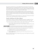
15. Navigate to the Coordinates rollout of the checker texture. Turn off Real-World Scale, and
adjust the U and V tiling while observing the effect. Changing the V tiling to 12 clearly
shows the checker following the path contours now, as in Figure 9.55.
16. To exchange the checker pattern with a bitmap, click the Material Type button to open the
Material/Map Browser, and then double-click Bitmap. In the Select Bitmap Image dialog
box, navigate to C:\Program Files\Autodesk\3ds Max Design 2011\maps\ArchMat,
and choose Masonry.Unit Masonry.Brick.Modular.Herringbone.jpg. Turn off Real-
World Scaling again; RWS is automatically activated when you apply a bitmap.
17. Turn on Show Standard Map in Viewport.
18. Adjust the U and V tiling to your taste. Zoom in if necessary so you can see a better view
of the mapping, as shown in Figure 9.56.
19. Save your file as MySplineMapping_Completed.max. Click the Exit Isolation button,
change the view to Perspective view, or add a camera to the scene and render it to see the
results.
As you have seen in the previous exercise, the Spline Mapping feature of the Unwrap UWV
map modifier makes mapping paved paths, striped roadways, or other splinelike objects easier
to map.
Figure 9.55
The result of adjusting
the V tiling on the
Checker Test material
Figure 9.56
Adjust the U and V
parameters of the
brick material.
addInG entouraGe
|
481
Adding Entourage
Entourage is a term taken from traditional architectural rendering. It refers to photographic
“extras” that are added to a rendering to make it appear more realistic. You can think of entou-
rage as cutouts or props that are added to the scene to make it more lifelike and help define the
scale of the scene. Examples of entourage are people, trees and plants, cars, street furniture, and
signs. Entourage is not composed necessarily of 3D models, however. As 2D photographic ele-
ments, they can be handled mainly through materials.
The key to designing an entourage material is to use an Opacity map to hide unwanted por-
tions of the surface to which the texture is mapped. Generally, entourage materials are applied
to Plane or Box primitives that act like flat billboards, displaying their contents for the world to
see. Once you apply an opacity-mapped material to an object, it is also important to adjust the
object to fit the bitmap’s aspect ratio or undesirable stretching will occur.
The AEC Foliage objects, covered in Chapter 6, “Creating AEC Objects,” also create entourage
objects with varying degrees of complexity.
Hiding Unwanted Surfaces with Opacity Maps
An opacity map is a grayscale bitmap image that tells 3ds Max which part of the surface is opaque
and which part is transparent. The black portions of an opacity map become completely transpar-
ent, whereas white is completely opaque. Shades of gray create varying degrees of opacity.
To see how this works, look at Figure 9.57. To the left you see an opacity map. The middle fig-
ure shows a simple box in 3ds Max without a material assigned to it. The figure to the far right
shows the same box that is assigned a material using the opacity map (or a cutout map) at the
left. Notice that the portions of the opacity map that are black appear invisible in the box.
You can also use shades of gray to simulate a semitransparent material or to gradually
change the transparency of a surface. Color images can be used for opacity maps as well,
although the color information is not used—only the pixel grayscale value is considered.
Now that you understand what opacity maps are, let’s design a tree material you can apply
to plane objects to use as entourage. While doing this, you’ll also have a chance to explore the
workflow for using the new Slate Material Editor.
1. Reset 3ds Max. To open the Slate Material Editor, go to the Rendering menu and choose
Material Editor Slate Material Editor. Alternatively, on the Main Toolbar there’s a flyout
Figure 9.57
An opacity (cut-
out) map and an
object to which it is
assigned
Opacity map Object Object with Opacity
map material applied
482
|
CHAPTER 9 enhanCInG Models wIth MaterIals
that lets you choose between Compact and Slate Material Editors if you’d rather use
an icon.
2. Right-click in the View1 window of the Slate Material Editor, and choose Materials
metal ray Arch & Design, as shown in Figure 9.58.
3. Right-click the top bar of the material, as shown in Figure 9.59, and rename this material
Magnolia. Then click OK.
Figure 9.58
Creating a new
Arch & Design
material in the
Slate Material
Editor
Figure 9.59
Rename the new
material Magnolia.
addInG entouraGe
|
483
4. Right-click in an empty area of the View1 window of the Slate Material Editor, and
choose Maps Standard Bitmap, as shown in Figure 9.60, to open the Select Bitmap
Image dialog box.
5. In the Select Bitmap Image File dialog box that opens, navigate to and select the magnoliaIM
.jpg file that you downloaded from the book’s website as your diffuse color image, and
click Open.
6. Click and drag from the gray circle on the edge of the Bitmap node, called the Output
Socket, in the View1 window to the gray circle next to Diffuse Color Map, called an
Input Socket, on the Magnolia material, as shown in Figure 9.61.
You have just wired the MagnoliaIM.jpg bitmap to the Diffuse Color Map channel of the
entourage material.
7. Double-click the Bitmap node to display its properties in the Parameter Editor section of
the Slate Material Editor.
8. Deselect the Use Real-World Scale option in the Coordinates rollout, change both the U
and V Tiling values to 1, and deselect the U and V Tile boxes.
9. Dial the Blur value down to as low as it will go, 0.01. This will make the texture look as
sharp and detailed as possible in your renderings.
10. Change the Preview Object Type to a box by right-clicking the Magnolia material node
and choose Preview Object Type Box, as shown in Figure 9.62.
Figure 9.60
Create a new
Bitmap node.
Figure 9.61
Connect the Bit-
map node to the
Diffuse Color Map
channel.
Click and drag from here
to here.
Figure 9.62
Changing the
material Preview
Object Type
484
|
CHAPTER 9 enhanCInG Models wIth MaterIals
11. Right-click the material node, and click Open Preview Window to see a larger version of
a material sample. This opens a small dialog box, which is similar to the Magnify win-
dow of the Compact Material Editor, which can be resized and which updates with any
parameter changes made to the material, as shown in Figure 9.63.
What is new about the Slate Material Editor Preview Window is that you have one pre-
view window that can show the currently selected material/map, a specific material in
the Active View Window, or any maps in the active view using the drop-down at the
bottom of the dialog box, as opposed to the Magnify window of the Compact Material
Editor, which displays only the material you selected.
12. Right-click in the Active View Window, choose Maps Standard Bitmap to open
the Select Bitmap Image dialog box, and select the magnoliaOP.jpg file, as shown in
Figure 9.64. You see the sample image of the magnoliaOP.jpg file in the lower-right
corner of the dialog box.
Figure 9.63
The Slate Material
Editor Preview
Window
Figure 9.64
Selecting the opac-
ity map