Autonomous Robotic Systems - Anibal T. de Almeida and Oussama Khatib (Eds) Part 9 docx
Bạn đang xem bản rút gọn của tài liệu. Xem và tải ngay bản đầy đủ của tài liệu tại đây (1.45 MB, 20 trang )
155
between individual trees. After a short time (less than 10 years) all trees are cut
down much like in field harvesting. This kind of operation would certainly be
suitable for robots. Planting is an another suitable task as well as silviculture, where
small trees are taken care of by cleaning their surrounding from other plants time to
time. It is highly manpower intensive work and is coming economically impossible
in many countries because chemical treatment is not allowed any more. Mechanical
treatment can be done by robots that are working in colonies like herd of lambs. An
example of such development is given in the next section. In generally there are at
least two basic reasons why this kind of multi-robot concept is of potential interest
as an engineering solution. The first reason is fault tolerance. A multi-robot system
has a high redundancy, because the functions of a faulty individual can be always
easily replaced by the other robots. The second reason is a robot to robot
communication structure which makes it possible to increase or decrease the number
of robots in a colony easily without any reconfiguration of the communication
structure. Applications where a long term fully autonomous operation is needed[
and/or the work to be done can be executed in a parallel way by a group of
individual robots are natural tasks for multi-robot systems. For more about the
multi-robot systems see e.g. [3] and [4].
Transportation perception and navigation technology for unmanned AGV-type of"
vehicles are quite ready at the moment and it will be interesting to see if and when it
will be realised in forestry. In some other areas, for instance in mining and
construction, autonomous transportation with heavy trucks is very close to be taken
into commercial use. Experiences this far indicate unambiguously that the most
accurate and reliable vehicle navigation system can be made by fusing a dead
reckoning gyro based navigation with a proper beacon based localisation system.
Practical beacon systems are either optical or based on radio frequencies (for an
excellent overview see [5]. By using a beacon system - even quite an inaccurate one
the drift error can be removed from the dead reckoning navigation system and its
relative accuracy can be utilised in full power. The most potential beacon system for
outdoor applications today is GPS (Global Position System) which is available
almost all over the world. In vehicle navigation it is mostly used in the differential
mode (DGPS) which gives around 5 m absolute localisation accuracy. With a
moderate dead reckoning navigation system and the fusion method described shortly
below the accuracy can be increased to the level of 0.5 m which is enough for most
forestry or other work site applications.
A very useful tool for fusion of two or more different measurement sources is
Kalman filtering. The idea is simple. We suppose here that the reader is familiar
with the basic theory of Kalman filter or more precisely with its extended form. If
not, one should become familiar with suitable text books, e.g. [6] and [7]. In the first
phase of forming the algorithms needed a suitable model which describes the
kinematic motion of the vehicle is derived. For wheel vehicles a simple "bicycle
model" is usually sufficient, because these machines are moving slowly. The model
is presented as follows,
156
(x(k+l)') (x(k))
(u~Tcos(O(k)))
I
+ II II
J
X(k+l)= / y(k 1)/=] y(k)]+/u~Tsin(O(k))],
\O(k+l)) \O(k)J ~ u 2T )
(1)
where (x,y) is position of the vehicle body coordinate system origo (often set in the
middle of the back axis) in some fixed world coordinate system, 0 the heading angle
of motion, ul is the longitudinal velocity of the vehicle and u2 the angular velocity
of the motion defined by the turning radius of the vehicle. The vector (x,y,0) is
estimated by using extended version of Kalman filter when the following
measurement equation is used
-x ,,,,,. ( k )
7
YD,,'S ( k )
Ix(k)l
z(k)=
X,,~,.,~(:KONZN~(k) +v(k)=H*|y(k)]+v(k).
(2)
| |
Y D,':AD.RZ;CKONm(; ( k )
L O
( k )J
O(k)
where v(k) is the measurement error vector (zero mean, white noise) and matrix H
has the following form
H= [[10100]r ;[Ol010]r;[oooo1]r ].
(3)
The measurement data vector z contains position measurements both from DGPS
and the dead reckoning system, and the heading measurement from the heading
gyro. A practical problem related to the data reading is the different sampling
intervals available. The dead reckoning instruments can be read with a high
frequency typically from 1 up to 10 kHz. The DGPS instead can be read typically
only with 1 to 2 Hz frequency. This problem can be solved by using a "little trick"
and modifying the Kalman filter equations. The basic sample interval is chosen
according to the high sampling frequency. The DGPS measurements are supposed
to be valid within a time window around the reading time, the width being typically
5 to 10 sample intervals to both direction. The part of the covariance matrix related
to the DGPS measurement is finite only in this time window and infinite elsewhere.
The Kalman filter can be written in the form
X( klk ) = 2( k k -1)+ K(z( k )- H * 2( k[k -1)),
(4)
15'7
X(kl,~ -1):
I A
x(k-llk-1 )
[(k-ilk-I)
O(k-lLk-1)
I
u~T
cos(O (k- llk- 1))]
+[.,r sin(O (k -llk -1)) t, (5)
Lu2T J
K : [Kl[ K2], (6)
3x5
where K~ represents the part of the gain which comes from the dead reckoning part
and
K 2
the part coming from the DGPS part. K z is non-zero only in the time window
mentioned above and thus contributes to the correction part of the filter.
For actual results of the method presented here see e.g. [8], where the positioning of
an autonomous off-road vehicle has been done by fusing DGPS and inertiall
navigation. At the moment the price of the navigation and perception system needed[
for autonomous operation is nevertheless still too high for forestry machines that are
not operated by industrial enterprises but small companies or individual farmers.
4. What exists?
Only few examples of forestry robots exist today. Most of them are still
development projects, which means that the robots are not in everyday work but are
used more or less for testing purposes. However, those described in the following
are serious attempts to develop products that most probably will be seen in a form or
another in real use in the future.
4.1 Walking harvester
Along with the tightening environment protection requirements forest harvesting has
to be executed more carefully, not harming the ecosystem more than necessary. The
typical harvesting machines, shown in Fig. 3, are relatively heavy and clumsy. They
may easily harm the ground infrastructure and roots of the standing trees if the
drivers are not very careful. This is mainly because of the locomotion system that
uses tracks and large wheels. Legged locomotion system is an interesting alternative
that has been already proven to be much more gentle to the ground infrastructure. A
legged machine with extra degree of freedom is also more flexible in
omnidirectional motion. Fig. 6 shows an experimental six legged machine, called
MECANT, developed at the end of 80's at Helsinki University of Technology, see
e.g. [9], to study walking locomotion in natural environment. MECANT is
hydraulically driven stand alone 1 ton machine that is remotely controlled. The
legged locomotion is fully automated by onboard computers and the operator can
use all six d.o.f, of the body within the kinematic limits. This means extra flexibility
when driving the machine on uneven terrain and in stabilising it in working position.
Although the machine is not autonomous, but driven remotly by an operator using
radio joy-stick, its locomotion system is robotic-like and needs a large software for
its functions. The piloting system of MECANT is divided into different planners, as
158
shown in Fig. 7 below. The main planners are the body motion planner, the gait
planner and the foothold planner [10]. In this figure the "transfer feet" mean feet
which are in motion in the air to find the next foothold, and the support feet mean
feet presently supporting the body on the ground.
MECANT MOT1ON PLANNING
i
J I I I [ /
j =: j
I I I J
I
I /
[
TRAJECTORIES
i TRAJECTORIES
i
Fig. 6: MECANT
Fig. 7." The motion planning of MECANT
The body motion planner determines the body motion trajectory according to the
operator's velocity commands, the vehicle's sensor data and the local terrain model.
The gait planner determines the "leg states" (support or transfer), and the phases and
state periods (time lengths of the support or transfer states) according to the gait
chosen.
The foothoM planner determines the optimal foothold position for a
recovering (transfer) foot.
The support trajectory planner calculates the velocities
and positions of the supporting feet, according to the velocity vector of the vehicle's
body.
The transfer trajeetol T planner calculates the velocities and positions of the
transfer feet. The functions of the planner can be further divided into different
phases, such as lifting, moving and placing.
The support force planner determines
the supporting forces of the feet. If the legs are purely force controlled, the
determination of the feet forces vectors can also be done in this planner. The body
motion planner, the support trajectory planner and the support force planner are the
same for every gait. The foothold planner, the transfer trajectory planner and,
naturally, the gait planner depend on the gait chosen. In [11] a gait planner that is
based on heuristic rules was presented. It took into account in every planning cycle
the temporal direction and velocity of motion, the availability of the legs to start a
new working cycle, the stability of the machine in the direction of motion, and the
possible collisions between neighbouring legs. This considered
free gait is
especially useful in conditions where the machine is executing omnidirectional
motion in rough terrain. Compared to wave gait or adaptive wave gait, a more
flexible motion and an improved stability could be obtained. Currently research is
continuing by implementing a
semidynamic walking into MECANT. The motivation
for this is to speed up the locomotion speed of the robot. The method is based on
continuos optimization of the stability. It is done by adding an extra velocity vector
component to the commanded velocity vector. This additional component drives the
centre of gravity of the vehicle towards the most stable point of the leg support
pattern. For more information see [12]. Another problem in the design of a walking
machine is the velocity of the machine. One has to constantly trade between the
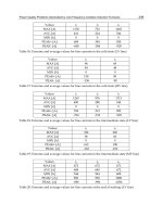
stability and the speed. Fig. 8 illustrates the relationship between the leg transfer
159
time and locomotion speed with different so called duty factors in periodic 6-legged
wave gaits. Duty factor 13 is calculated as follows
13 ='c
s
/ z, (7)
where "c s is the leg support time and 1; is the leg cycle time. Basically the duty
factor value of n/6 indicates that n legs are supporting a six-legged vehicle during
the locomotion cycle. Fig. 8 shows that if a maximum stability is needed (i.e. 13 =
5/6) and the locomotion speed should be 2 m/s, a leg transfer velocity of more than
15 m/s is needed. Needless to say that this kind of leg movement is very hard if not
impossible to obtain. On the other hand if we are happy with minimum stability (i.e.
13 = 3/6) the locomotion speed can be reached with only 3m/s leg transfer velocity.
For more extensive study on this matter see e.g. [13] and [14].
leg trans~e~ yelocity vs. hx"omotio~ -'~"~ f¢¢ 6-1cgged wave gaits
35~
s~oke = 0i5 m
30 ! i ~
I i :: ~t~=516
i"'~
25[
~ ~ ~
2o I i
i
Is i ~ i
10 1 i beta-
4/6
:t-
316
0 1 2 3
locomotion speed (w)s)
Fig.8: The average velocity of transfer foot as a fimetion of locomotion speed in periodic 6-
legged wave gaits l14].
Regardless of the presented limitations, the benefits of walking locomotion are so
numerous, that the publishing of a prototype forest harvester in 1995 (by Plustech
Ltd, Finland), shown in Fig. 9, was not at all unexpected.
Fig. 7." Prototype walking harvester (TimbeJjaclc/Plustech Ltd)
160
The machine is based on walking locomotion system and standard harvesting tool
(see ). It has been used in test work during a full year in
Nordic climate and experiences this far are positive. Especially the environment
friendly properties have turned out to be better than expected. Within next few years
it is probable that this technology becomes commercial in certain areas of the world
where forest harvesting is under strong environmental regulations, like in
Scandinavia and central Europe.
4.2 Slope climbing machine for silviculture applications in
mountain areas
Another type of semi-walking machine for forestry use has been developed in Japan
in co-operation with Tokyo University Forestry Department and a forestry company.
This machine is intended for steep slope operations like thinning, brushing and
planting. In Japan the forests are growing mainly on hillside and forestry operations
are sometimes extremely difficult. The prototype machine is shown in Fig. 8.
Fig. 8." Slope climbing machine
It has three front legs that can perform gaiting and two rear wheels that are not
powered but have brakes. The centre leg can be used also as a manipulator. When
writing this the authors did not know whether or not the prototype has been already
made commercial.
4.3 Multi-robot system for brushing and thinning
of young trees
An interesting multi-robot concept for brushing and thinning of young trees has
been developed in Canada by Petawawa National Forestry Institute, see e.g. [15].
This kind of operation is important especially during the first years after planting to
provide the best possible growth condition for young trees. Traditionally the work
has been done manually by using chemicals or mechanical tools. Today only
mechanical treatment is possible and there is typically a lack of manpower to do the
job. The idea in the project is to develop a multi-robot "heard" of slowly walking
light weight machines that can find the plant and brush its environment. The most
difficult problem is perceptive, i.e., to find the young tree among the grass and other
vegetation. This is now under solving by using colour camera and image processing.
The vehicle itself, shown in Fig. 9, is still a research prototype, but the development
has continued in a company called AutonomoUs Walking Machines Inc.
See
www.pfc.forestry, ca/www_users/
fgougeon/rem_sens/FG_R V. html
for detailed description
1 (}1
Fig. 9: The prototype robot, Jacob, for brushing and thinning
The basic idea in this project is very good and it is quite sure that it can be
commercialised provided a good solution for the difficult perception problem can be
found.
5. Discussion and conclusions
Many scenarios about the future development of forestry robotic technology can be
made. One is illustrated in Fig. 10. We will see real applications of robotic
technology, remote handled machines, multi-machine mobile operation stations and
even applications with high level autonomy. There are three basic factors that
affects this development:
environment consciousness of people, availability of
manpower and cost of technology.
All these factors indicate at the moment that there
will be a radical change in technology during the next 10-15 years.
!/.A.
I
t,
For most of the new applications the technology basis already exists, see an
overview in [16]. It is more question of when and in what form the applications will
mature for commercial markets. One fact that sets a high threshold for acceptance of
the new technology in this field is the mode of action in forestry business. In most
cases the operations are taken care off by small contractor companies or even
162
individual farmers whose possibilities to invest in technology are limited. Reliability
and easy maintainability of the technology are also of crucial importance. The
situation is much different as for instance in mining. This makes the machine
makers in the field also conservative. However, the factors mentioned above are also
strong and, as we have seen during the last ten years, they have influenced strongly -
in fact more strongly than what was predicted in the mid 80's.
References
[1] Halme A, Heikkilfi T, Torvikoski T 1987 An Interactive Robot Control System.
International Journal of Robotics and Automation,
Vol. 2. No 3.
[2] Manninen M, Halme A, Myllylfi R 1984 An Aimable Laser Time-of-Flight Range Finder
for Rapid Interactive Scene Description. In:
Proceedings of the 7th Annual Conference of
British Robot Association,
Cambridge
[3] Halme A, Jakubik P, Sch6nberg T, Vainio M 1993 The Concept of Robot Society and Its
Utilization. In:
Proceedings of the IEEE/Tsukuba International Workshop on Advanced
Robotics,
pp 29 - 35
[4]
Distributed Autonomous Robotic Systems 2
1996. Asama H, Fukuda T, Arai T, Endo I
(eds), Springer-Verlag, Tokyo
[5] Everett H R 1995
Sensors for mobile robots: theory and applications,
A K Peters,
Wellesley, MA
[6] Maybeck P S 1979
Stochastic models, estimation and control, Vol.1,
Academic Press,
New York
[7] Maybeck P S 1982
Stochastic models, estimation and control, Vol.2,
Academic Press,
New York
[8] Sch0nberg T, Ojala M, Suomela J, Torpo A, Halme A 1996 Positioning an autonomous
off road vehicle by using fused DGPS and inertial navigation.
International Journal of
Systems Science,
Vol. 27, 8:745-752
[9] Hartikainen K, Halme A, Lehtinen H, Koskinen K 1992 Control and Software Structures
of a Hydraulic Six-Legged Machine Design Ibr Locomotion in Natural Environment. In:
Proceedings of lROS'92,
pp 590-596
[l 0]Hahne A, Hartikainen K, Karkkainen K 1994 Terrain Adaptive Motion and free Gait of a
six-legged Walking Machine.
Control Engineering Practice.
Vol. 2, 2:273-279
[11]Sahni S, Halme A 1996 hnplementing and testing a reasoning-based free gait algorithm
in the six-legged walking machine "MECANT".
Control Engineering Practice.
Vot. 4, 4:
487-492
[12]Halme A, Salmi S, Leppanen I 1997 Control and stabilisation of the semi-dynamical
motion of a heavy six-legged walking machine. In:
Workshop of Walking Machines,
(ICAR'97),
July 6 1997, Monterey
[13]Halme A, Hartikainen K 1996 Designing the Control System of an Advanced Six-Legged
Machine. In: Gray J O, Caldwell D G(eds) 1996
Advanced Robotics & Intelligent
Machines,
The Institution of Electrical Engineers, London, pp 177-190
[14]Hartikainen K 1996 Motion planning of a walking platform designed to locomote on
natural terrain.
Ph.D. Theszs,
Helsinki University of Technology.
[15]Gougeon F A, Kourtz P, Strome M 1994 Preliminary research on robotic vision in a
regenerating {brest environment. In: Borkowski A, Crowley J L(eds)
Int. Syrup.
Intelligent Robotic Systems '94,
pp 255-262
[16]Halme A 1995 Mobile Robotics in Unstructured Environments - Some Advanced
Applications, In:
Proceedings of the 1995 National Conference of the Australian Robot
Association,
Australian Robot Association (invited paper), Sydney
Robotics for the Mining Industry
Peter I. Corke and Jonathan M. Roberts and Graeme J. Winstanley
CSIRO Division of Manufacturing Science and Technology
CRC for Mining Technology and Equipment
P O Box 883, Kenmore, Queensland 4069, Australia
http ://www. cat. cs iro. au/automat
ion
Abstract:
The mining industry is highly suitable for the application of
robotics and automation technology since the work is both arduous and
dangerous. However, while the industry makes extensive use of mechani-
sation it has shown a slow uptake of automation. A major cause of this
is the complexity of the task, and the limitations of existing automation
technology which is predicated on a structured and time invariant work-
ing environment. Here we discuss the topic of mining automation from a
robotics and computer vision perspective as a problem in sensor based
robot control, an issue which the robotics community has been studying
for nearly two decades. We then describe two of our current mining au-
tomation projects to demonstrate what is possible for both open-pit and
underground mining operations.
1. Introduction
Automation in mining is desirable because it offers the advantages of:
• higher
productivity;
• increased safety, by reducing human exposure to hazards;
• reduced operating stress on equipment.
Most of the productivity increase in mining this century has been due to
mechanisation. Mines have moved from using predominantly human and ani
mal power to large electric and diesel powered machines. The trend in the past
thirty years has been towards larger and more powerful machines but practical
limits have now been reached. Underground machines are further constrained[
by the dimensions of the tunnels in which they operate. As growth in machine
size tails off, other approaches must be pursued
in
order to achieve productivity
growth. Automation is a strong contender due to the phenomenal growth in the
capability of sensing, control and computing technologies over the last decade
and the reduction in cost. The focus of the two projects described in this chap-
tar is on increasing productivity of existing capital assets by retrofitting with
enhanced sensing and control technology.
Mining is a dangerous occupation and despite almost continuous improve-
meat fatalities still occur. In addition there are a great many other serious
164
injuries and subtle long-term health risks due to noise, dust and fume inhala-
tion, and vibration. Safety can be best improved by removing people from the
dangerous parts of the mine and other health damaging occupations.
Maintenance is also a significant cost in mining, estimated to be as high
as 30% of the total costs. Automated systems provide a non-obvious benefit
through controlled demands on the machine, operating it within its design
envelope. This will lead to reduced wear and tear and thus significant cost
savings.
However despite all these apparent advantages mining automation has pro-
gressed far more slowly than factory automation. The principal reason is that
automation is feasible only when the machine "knows" its environment. In in-
dustrial applications, considerable engineering effort is expended in providing
a suitable work environment for machines. This entails the design and manu-
facture of specialised part feeders, jigs to hold the work in progress, and special
purpose end-effectors. High non-recurrent engineering costs are incurred, but
automation can proceed since the environment is known and can be described.
A great many tasks routinely performed by humans in unstructured en-
vironments (for example machine control and driving) are based on visually
perceived information. In order for robots to perform such tasks, without ex-
tensive instrumentation or re-engineering of the environment, they must also
have the ability to perceive and act upon visual information. Computer vision
is therefore an important sensor for robotic systems since it mimics the human
sense of vision and allows for non-contact measurement of the environment. Vi-
sual control, or visual servo, systems[l, 2] are those in which a machine vision
sensor is used to provide position feedback for a machine. Much of the research
in laboratories is based on small electric drive robots but the techniques are
applicable to machines of the scale used in mining. This is an area of great
current research interest and many robotic systems have been demonstrated
in indoor laboratory environments. Some, such as the HelpMate robot, are
in commercial operation. The mining environment is arguable much harsher,
is continuously changing (it could be argued that this is the purpose of min-
ing), and the machines involved are extremely large and powerful and hence
dangerous if not controlled correctly.
The next two sections discuss in some detail two of the applications that
currently being investigated at the Centre for Mining Technology and Equip-
ment.
2. Dragline
automation
Draglines are used to remove overburden 1 and uncover coal. As remaining coal
seams become deeper, more overburden must be removed to uncover the same
amount of coal, and this has become a bottleneck in the production process.
At a cost of $50M to $100M, buying another dragline is a major investment
for any coal mine, so improvement in productivity through automation is of
considerable interest. Quite modest improvements in productivity, for example
1 The economically valueless material which covers a coal seam.
165
4%, would produce a benefit of $3M/year per dragline.
A dragline, see Figure 1, comprises a rotating assembly that includes the
'house' (drive motors, controls, and operator cabin), tri-structure or mast, and
boom. The house rotates on a bearing surface on top of the 'tub' which sits
on the ground. A large diameter ring gear is fixed to the tub and the house
is rotated by a number of pinions driven by motors in the house. A walking
dragline is able to drag the tub along the ground by means of large eccentrical]y
driven 'walking shoes' at the side of the machine.
The dragline has three driven mechanical degrees of freedom:
• the house and boom can
slew
with respect to the tub;
• the bucket can be
hoisted
by a cable passing over sheaves at the tip of the
boom;
• the bucket can be
dragged
toward the house by a cable passing over sheaves
at the base of the boom.
During digging the bucket motion is controlled using only the drag and hoist
ropes. When the bucket is filled it is hoisted clear of the ground and swung to
the dump position by rotating the house and boom. The drag and hoist drives
now control the position of the bucket within a vertical plane that contai~Ls
the centerline of the boom however the bucket is free to swing normal to that
plane.
As can be seen from the Figure 1 draglines are very large machines. Typical
draglines have boom lengths of over 100 m, weigh up to 5000 tonnes, and can
employ up to sixteen 500 hp motors on the slew drive and bucket capacity can
range from 100 to 250 tonnes.
A good deal of operator skill is required to control, and exploit, the bucket's
natural tendency to swing. An early attempt to automate bucket swing by
replaying a taught sequence of operator setpoints was unsuccessful, and we
believe this was due to the lack of knowledge about the instantaneous state of
the swinging load.
A complete cycle takes around 1 minute to complete, of which 80% is
swinging the bucket through free space it is this portion of the cycle that we
propose to automate. Our work is based on the observation that control of the
bucket moving through free-space is really a robotics problem. The electric-
drive dragline can be considered to be a 3DOF robot with a flexible final link:.
The proposed swing automation system will be activated by the operator once
the bucket is filled. It will automatically hoist, swing and dump the bucket
(at an operator set reference point) before returning the bucket to a predefined
digging point. Our prototype is a 3500 tonne Bucyrus-Erie 1370 dragline which
is in production 24 hours/day, and this greatly constrains the physical access
we have to the machine for fitting automation components and testing. Earlier
experimental work on a one-tenth scale dragline [3] was used to demonstrate the
automation concept to the industry. Modelling of the mechanical and electrical
components of a production dragline and their control are discussed further in
[4].
166
Figure 1. Annotated picture of the Bucyrus-Erie model 1370 dragline.
2.1. Bucket position sensing
As stated above a good deal of operator skill is required to control the bucket
swing. The motion of a dragline bucket with respect to the boom can be
considered as a pendulum with the ropes and aerodynamic forces providing
some damping. Control of such a system requires a knowledge of the bucket
position. Existing encoders on the winch drums provide hoist and drag rope
lengths which define a locus along which the bucket moves, but the swing angle
with respect to the boom is not known.
The bucket's harsh interaction with the environment precludes the use of
instrumentation on the bucket itself. Various remote sensing techniques were
investigated, but the specifications are stringent. The sensor must be capable of
operating completely reliably 24 hours a day in all weather conditions, at a rate
of at least 3 Hz (control constraint), and irrespective of changes in bucket type,
contents, distance and orientation. An extensive experimental program [5]
established that it was not practical to identify by the bucket against the mine
background by conventional vision techniques. The deficiencies of the machine
vision approach are best illustrated by the raw and edge bucket images, from
a boom-tip mounted camera on the BE1370, shown in Figure 2. Real-world
effects such as uncontrolled lighting, shadows, background texture and motion,
and lack of contrast combine to thwart all approaches that we evaluated.
The approach that we selected instead is based on a scanning infra-red
laser range finder (SICK Optic PLS), mounted near the boom tip to find the
location of the hoist ropes. Figure 3 shows the PDF of target bearing and range
occurrence for over 1000 trials in normal daylight conditions and in heavy rain.
The heavy rain introduces small spikes but the hoist ropes are still clearly dis-
cernible and can be reliably located with a tracking filter. Preliminary results,
167
Figure 2. BE1370 bucket images (a) raw bucket image. (b) edge image.
Figure 4, show the range and bearing of the midpoint of the two hoist ropes
during machine operation.
The sensing unit is mounted on a special platform just below the boom
point sheaves (see Figure 5). The unit's associated electronics are mounted
in a weatherproof cabinet on the boom. Raw data is sent back to the control
computer via an optically isolated high speed RS422 serial link. The bucket
sensing system combines the angle information from the rangefinder with the
length of the hoist and drag ropes to determine the position of the dragline
bucket in 3D space.
2.2. Dragline computer system
The control computer is a VMEbus PowerPC with dragline control and status
signals connected to the control computer via Industry Pack (IP) interface
modules. The quantities monitored include motor armature voltage, motor
armature current, regular input voltage from the operator's control, and winch
drum and house rotation.
The boom mounted PLSs connect to an industrial PC that processes the
raw PLS data and sends hoist rope angle details to the control computer pro-
cessor via a local 10BaseT network. Both computers run the real-time multi-
tasking operating system LynxOS.
The computers are powered by a mains filtered UPS. All signals between
the dragline house and the boom and mast units are connected via arrestors
to protect against lightning strikes. Variations in ground potentials between
different parts of the dragline are overcome by optically coupling signals into
and out of the control computer interface.
A radio LAN, mounted on the dragline mast, allows remote code develop-
ment and monitoring of dragline operation. The latter is necessary to establish
parameters for our dynamic models of the dragline [4]. The other end of the
radio
LAN, up to 1 km, is a caravan that serves as a mobile laboratory fol~
code development and data analysis without requiring a physical presence on
the dragline.
168
~o.
"5
~0.
,'d
~o,
D-
Bear,ng taeg)
0
(a!
Range(mt
t0
`5
~o.
q,0,9868
10
Bearing (deg) 0
Range (m)
(b)
Figure 3. PDF of target bearing and range occurrence over 1000 trials (a) hoist
ropes in daylight. (b) hoist ropes in heavy rain. The two large spikes in the
centre of the figures represent the dragline hoist ropes; the large spikes on the
right are artifacts of the test range.
2.3. Operator interface
An operator controls the dragline by means of a joystick for each hand (drag
and hoist rope rate control) and a set of pedals to rotate the house left and
right. Our automation system 'drives' the dragline by physically moving the
control joysticks and pedals; somewhat like the cruise control in a car or the
auto-pilot of a fly-by-wire aircraft. To achieve this we have fitted servo motors
to each of the control devices.
Servoing these controls facilitates the smooth transfer of system set points
between the automatic system and the operator. The servoed operator controls
also restrict the control computer to the same safety interlocks and limits as
151
~ q
Io~- :
¥ • ,
5
0
:
"
i -5
_101 i i • L i
0 50 100 150 200
Time (s)
6 A
E'5L~4 /i~l
2 / I
0 5O
t00
i
150 200
Time (s)
Figure 4. Hoist rope motion during dragline operation.
250
4,
I
250
169
Figure 5. Location of major automation system components.
applies to input from an operator. Error sensing on the hoist and drag joysticl~:
servo motors allows the automatic system to sense if the operator is opposing
the motion of the joysticks, in which case it smoothly transfers control of the
dragline back to the operator.
170
2.4. System safety
The control system is designed to be fail safe; that is, it reverts to operator con-
trol should a system failure be detected. Watchdog timers ensure the consistent
operation of the control computer and servoed operator controls. The system
software incorporates both parameter range and change checks. A control pen-
dant is used for testing the automation system. It ensures that a conscious
physical action must be taken before the dragline can be placed in automatic
mode, and a 'kill' button can immediately disable the automatic mode.
2.5o Summary
The automatic system is being deployed in two stages. Stage 1 is a logging
phase in which the automatic system will be installed without any servoed
operator controls. In the logging configuration the automatic computer system
will be debugged and dragline characteristics required for the programming of
the automation system will be measured. Stage 1 is scheduled to be installed
in the second quarter of 1997.
Stage 2 of the deployment process involves the installation of the operator
accepted servoed controls and the testing of the system in an automatic con-
figuration. The servoed operator controls are scheduled to be installed in the
third quarter of 1997 with testing of the automatic system commencing in the
fourth quarter of 1997.
We see the current automation project as the first in a series that will
eventually lead to fully automatic dragline operation. With the automation
system operating we can use it as a platform to investigate issues such as
automated bucket filling, kinaesthetic feedback of motor torque to the operator
via the servoed control, dumping directly into a hopper or truck, and online
planning based on local terrain sensing. These are all stages along the path to
a fully autonomous operation.
3. Underground mining robotics
Many tasks in underground hard-rock (not coal) mining are performed by man-
ually controlled hydraulic arms (known as 'booms') carrying tools such as drills,
rock-breaking hammers, explosive charging hoses, shotcrete applicators, or cas-
settes of ground support bolts. A typical rock-breaking boom and tool is shown
in Figure 6 and the similarity to a robot is clear, but all these underground
machines are 'driven' by operators. A common characteristic of these booms
is that are quite compliant, have considerable mechanical 'slop' in the joints,
and the payload to self-mass ratio is much higher than for a factory robot.
The tasks performed by the operator typically involve positioning the tool
with respect to some feature in the local environment, for example, positioning
a rock breaker over a large rock to be broken, or a support bolt or an explosive
charging hose into a pre-drilled hole. The operator is generally at a considerable
disadvantage since the boom's compliance causes the end-point to bounce, the
controls actuate joints directly rather than commanding motion in task space
coordinates, and the operator sits a considerable distance away from the tool
(up to 5 m) and the lighting is often poor.
171
Figure 6. A rock breaker.
Most underground mining machines utilise hydraulic actuation with elec-
trically driven valves, thus knowledge of electro-hydraulic systems is critical for
automation purposes. Hydraulically actuated robots are not commonly used
by the robotics research community, and those that do exist often make use of
servo or precision components. In order to learn more about this technology a
laboratory rig, shown in Figure 7, has been built to test our control concepts.
The prototype was designed to simulate the mechanical and dynamic charac-
teristics of typical underground hydraulic machinery, and with regard for issues
such as robustness in underground use. We use standard proportional valves
rather than the less rugged servo valves commonly used in much research work,
and the hydraulic actuators have rugged inbuilt ultrasonic length transducers.
Our approach to modelling the characteristics of the laboratory manipulator is
described in [6].
The remainder of this section presents some preliminary results in 3D
sensing and discusses the conceptual design of a semi-automated rock breaking
system that demonstrates the need for sensing, control and human supervision.
172
Figure 7. The laboratory electro-hydraulic boom.
3.1. 3D sensing
We are investigating a number of techniques for 3D sensing[7] such as stereopsis,
scanning laser rangefinders, and structured lighting. Some early experimental
results for the first two of these techniques are given in this section.
The early approaches to computer vision, were based on what would today
be called passive computer vision. That is the computer analyses one or more
digital images of a scene and attempts to interpret the scene, its components,
and their interrelationship. Although seemingly simple, we do this all the time
in everyday life, it remains an extremely difficult task for a computer. The
human eye relies on many subtle visual cues in order to distinguish objects in
a scene and their 3-dimensional structure[7].
Over the last decade an alternative approach, active ranging, has become
technologically feasible. Here the scene is subject to controlled illumination,
often in the form of a scanned laser, which enables direct measurement of
scene 3-dimensional structure. Typically laser time of flight or triangulation
between the light source and the camera is used. Much of the inherent ambi-
guity in attempting to analyse an image of a scene is removed by this direct
approach. Such direct 3-dimensional sensing systems have been applied to vehi-
cle navigation[8], and with ranges up to 100 m would seem to have considerable
application in mining.
3.1.1. Stereo vision
Passive 3D vision has been extensively investigated for over 20 years by com-
puter vision researchers[7] and for over 150 years by photogrammetrists[9].
Photogrammetry is a mature technology that is already widely used in the
mining industry, particularly for open-pit mapping. The automation applica-
tions fit into the category of
close-range or terrestrial photogrammetry.
Stereopsis[7] computes range from disparity, the phenomenon by which the
image ofa 3D object point shifts as the viewpoint is moved laterally to the depth
axis. A stereo pair is typically taken by two cameras horizontally separated
by a distance known as the
baseline. The fundamental issue is to establish
correspondence or matching of points between the two images in order to derive
173
(~)
(b)
Figure 8. (a) Left and right camera images from the JISCT image database,
(b) Dense disparity (inverse depth) image obtained using normalised cross
correlation matching (NCC). Light pixels are closest to the camera (Figures by
Jasmine Banks).
disparity, and thence depth. Dense stereo matching involves performing this
matching for every pixel in the scene and is computationally intensive.
If the correspondence is to be determined visually there must be sufficient
visual 'information' at the matching points to establish a unique pairing re-
lationship. The most common difficulties encountered in practice are where:
the images have uniform intensity, regular repetitive texture will result in am-
biguous matching, or some part of the scene appears in only one of the views
because of occlusion effects (the
missing parts problem).
The approaches that we have investigated include standard techniques
such as sum-of-absolute difference, sum-of-squared-differences and normalised
cross-correlation[10], see Figure 8. The latter gives the highest quality disparity
images and is the most robust to variations in intensity between the cameras.
In practice stereopsis has been found to work well with mining images due to
the rich natural texture available. However lighting levels are critical to achieve
low noise images which are required for reliable matching. Execution time is
of the order of around 20 s for a 512 × 512 pixel image (on a 200 MHz Pentium
Pro), but this will reduce in the future as a consequence of Moore's Law.
174
Figure 9. The CMTE Mark I imaging laser range finder, comprises a PLS laser
scanner mounted on a custom 'nodding head'.
More recently, non-parametric measures have been proposed [11] which are
based on rank or order statistics. Such measures are amenable to custom
hardware implementation[12, 13] and can achieve frame rate performance for
limited resolution images of 256 x 256 pixels.
3.1.2. Scanning laser rangefinder
The SICK Optic PLS (see also Section 2.1) is a time of flight rangefinder that
measures range and bearing to points in a plane. In order to build up an area
range image it is necessary to scan or move the device over the target scene.
We constructed a "nodding head", see Figure 9~ that uses a servo motor to
rotate the entire scanner about an axis close to the axis of the sensors internal
rotating mirror. The scanning plane can be servoed through t80 degrees using
an Industry Pack servo module.
Figures 10 to 12 show some results from the PLS/nodding-head setup.
These data were collected during a field trip. Figure 10 shows the results of a
number of scans of a working grizzly (see Section 3.2). The diagram at the top
left of the figure shows the position of the scanner which was far from optimal,
resulting in the data containing shadowed regions behind large rocks. The