Bio-MEMS Technologies and Applications - Wang and Soper (Eds) Part 2 pot
Bạn đang xem bản rút gọn của tài liệu. Xem và tải ngay bản đầy đủ của tài liệu tại đây (543.72 KB, 19 trang )
UV Lithography of Ultrathick SU-8 23
1. Clean Si wafer with acetone, IPA (isopropyl alcohol), and DI (deion-
ized) water.
2. Spin coat SU-8 100 at 400 rpm.
3. Level hot plate, bake 10 hours at 110°C, cool down to 60°C inside 1
hour, dwell at 55°C (uncross-linked SU-8’s glass temperature is 50°C
to approximately 60°C) for 4 hours, cool down to room temperature
inside 3 hours.
4. Expose the sample using a broadband light source (with spectrum
total exposure dosage of 2 J/cm
2
, for PMMA filter wavelength selec-
tion exposure (with spectrum as shown in Figure 2.6; includes the
h-line and g-line) with total exposure dosage 12 J/cm
2
.
5. Postbake at 110°C for 20 minutes, cool down as in step 3.
6. Develop sample using SU-8 developer at 32°C with SONOSYS
megasonic actuator driven with a 250 W power supply for 2 hours.
The megasonic transducer was placed in a water bath supporting a
quartz tank in which the developer and substrate were located.
Wafers were facing the megasonic actuator.
7. Rinse sample with IPA several times, dry naturally.
To measure the sidewall quality of the microstructures fabricated using
filtered a light source and gap compensation, a 20 µm feature-sized micro-
structure with a flat edge was removed from the substrate and placed on the
measurement stage of the Veeco optical profiler. The R
s
(roughness of stan-
dard deviation) was then measured along the 1150 µm length. It was found
that the roughness of standard deviation (in the light incident direction) was
2.72 µm over the entire length of 1150 µm.
tions: (a) broadband light source with no air gap compensation, (b) broad-
band light source and air gap compensation using a glycerin solution, (c)
the filtered light source (i-line eliminated) with no air gap compensation,
and (d) filtered light source with gap compensation using a glycerin solution.
The minimum designed thicknesses of the crosses achieved are 20 µm for
the air gap and 8 µm for the glycerin gap compensation. The dark region in
Figure 2.7a was due to the residuals of the development.
The theoretical optical resolution of the line and space of the width b can
be estimated by the following equation:
where b is the width of line or space, λ is the wavelength of the lithography
light, s is the air gap between the mask and the photoresist, and d is the
bsd
min
()=+
3
2
1
2
λ
DK532X_book.fm Page 23 Tuesday, November 14, 2006 10:41 AM
as shown in Figure 2.6; includes the i-line, h-line, and g-line) with
Figure 2.7 shows a group of microcrosses produced with different condi-
© 2007 by Taylor & Francis Group, LLC
UV Lithography of Ultrathick SU-8 25
compensation with glycerin have excellent sidewall quality and resolutions.
Both structures were developed all through and clearly separated. The top
fingers are removed together by the liquid surface tension in the drying
process.
2.4 Basic Steps for UV Lithography of SU-8 and Some
Processing Tips
The standard lithography processing procedures of SU-8 include: (1) pretreat
the substrate, spin-coat SU-8; (2) preexposure bake, UV exposure (320 to 450
nm); (3) postexposure bake; and (4) development. The process parameters
determine the final quality of the microstructures. The curing process of SU-
8 is completed in two steps: formation of acid during optical exposure and
thermal epoxy cross-linking during the postexposure bake. A flood exposure
or controlled hard bake is recommended to further cross-link the exposed
SU-8 microstructures if they are going to be used as parts of the final prod-
ucts. Because most of the publications in the field do not provide detailed
lithography conditions, beginners often have to learn from their own expe-
riences and the learning curve can sometimes be exceptionally long. Some
basic lithography conditions are provided here as guidelines for those read-
ers who may need something to start from [21–24].
2.4.1 Pretreat for the Substrate
To obtain good adhesion for SU-8 on a substrates, the substrate needs to be
cleaned with acetone, IPA, and DI water sequentially, and then dehydrated
FIGURE 2.8
Comb structures made using filtered light source and gap compensation with glycerin.
DK532X_book.fm Page 25 Tuesday, November 14, 2006 10:41 AM
© 2007 by Taylor & Francis Group, LLC
26 Bio-MEMS: Technologies and Applications
at 120°C for 5 to approximately 10 minutes on a hotplate. The substrate may
also be primed using plasma asher immediately before spin-coating the
resist. In addition, an adhesion promoter may be used as needed. For the
applications involving electroplating metals and alloys and stripping of
cured SU-8, the vendor of SU-8, MicroChem, recommends using OmniCoat
before coating of SU-8.
2.4.2 Spin-Coating SU-8
The thickness of SU-8 film is dependent on several factors: the viscosity of
the SU-8 used, the spin speed, and the total number of turns. The vendor of
SU-8, MicroChem, provides some spin-coating curves for different SU-8
formulations, such as SU-8 5, SU-8 50, and SU-8 100. Some research labs have
also developed their own spin-coat curves based on the particular equipment
used. Figure 2.9 shows some typical spin-coating curves of SU-8.
FIGURE 2.9
Selective SU-8 spin-speed vs. film thickness curve. (Courtesy of Mark Shaw, MicroChem Corp.,
Newton, MA.)
SU-8 spin speed curves
0
5
10
15
20
25
30
35
40
45
750 1000 1250 1500 1750 2000 2250 2500 2750 3000
3250
Spin speed (rpm)
Film thickness (microns)
SU-8-2
SU-8-5
SU-8-10
SU-8-25
SU-8 spin speed curves
0
50
100
150
200
250
750 1000 1250 1500 1750 2000 2250 2500 2750 3000 3250
Spin speed (rpm)
SU-8-50
SU-8-100
DK532X_book.fm Page 26 Tuesday, November 14, 2006 10:41 AM
© 2007 by Taylor & Francis Group, LLC
UV Lithography of Ultrathick SU-8 27
Bubbles formed during the spin-coating step may lead to reduced lithogra-
phy quality. To eliminate bubbles in resist film, the substrate should be placed
on a flat and horizontal plate for 2 to approximately 10 hours before prebake.
This is an especially critical step for obtaining good quality of thick SU-8 film.
2.4.3 Soft Bake
The spin-coated sample needs to be soft baked to evaporate the solvent on
a leveled hotplate or in convection ovens. The heat transfer condition and
ventilation are different for the hotplate and the convection ovens, and the
preferred soft baking times are therefore different as shown by the curves
for measured soft baking times in Figure 2.10. Ramping and stepping the
soft bake temperature is often recommended for better lithography results.
The glass temperature of the unexposed SU-8 photoresist is about 50 to
approximately 60°C. Figure 2.11 shows a typical soft-baking temperature
curve used in our laboratory. This soft-bake process consists of multiple steps
of ramping up, dwell, and ramping down. The total cooling time is about 8
FIGURE 2.10
Soft bake time vs. SU-8 thickness.
FIGURE 2.11
A selected soft bake profile for 1100 mm–thick SU-8 film.
10
8
6
Bake time (hours)
4
2
0
0 200
ickness (µm)
Soft bake time vs. thickness
400 600 800 1000
Bake in oven
Bake on hot-plate
Dwell at 50°C/4 hrs
Ramp to 50°C in 40 m
Dwell at 75°C/15 ms
Ramp to 75°C in 40 mRamp to 110°C in 30 m
Dwell at 75°C/15 ms
Ramp to 75°C in 30 m
20°C/1~2 hrs
Ramp to 20°C in 3 hrs
Dwell at 110°C/10 hrs
DK532X_book.fm Page 27 Tuesday, November 14, 2006 10:41 AM
© 2007 by Taylor & Francis Group, LLC
28 Bio-MEMS: Technologies and Applications
to approximately 10 hours for a 1000 µm–thick SU-8 resist. For ultrathick
SU-8 film (more than 1000 µm thick), a baking temperature of 110°C is used
coated with Cr/Au film (as commonly used in the UV-LIGA process as the
plating seed layer), a 110°C bake temperature is suggested instead of 96°C. At
the same time, the bake time should be slightly reduced.
2.4.4 Exposure
A near UV (320 to 450 nm) light source is normally used for lithography of
SU-8. As the wavelength of the light source increases, the absorbance of the
light reduces and the transmission increases significantly. The transmission
increases from 6% at λ = 365 nm to about 58% as the wavelength increases to
405 nm. SU-8 has high actinic absorption for wavelengths less than 350 nm,
but is almost transparent and insensitive for above 400 nm wavelengths.
Because of the high absorption of SU-8 for light with shorter wavelengths, a
light source dominated by shorter wavelength components often results in
overexposure at the surface of the resist and underexposure at the bottom part
of the resist layer. This is the main reason that UV lithography of SU using an
i-line-dominated light source tend to produce microstructures with T-topping
geometric distortions. Thickness of the resist is another key parameter that
dictates the required dosage of the exposure. Figure 2.12 shows two curves
of required exposure dosage and the thickness of SU-8. MicroChem, the
vendor of SU-8, advises that the user filter out the light with a wavelength
lower than 350 nm to improve lithography quality. After filtering the light
components with wavelengths shorter than 350 nm from the light source of
the Oriel UV station used in our laboratory, with its spectrum as shown in
kept in a range of 1:7 to approximately 1:10 to achieve perfect vertical side-
walls, especially for the SU-8 resist with thickness around 1 mm. For lithog-
raphy of a very thick resist, multiple exposures are required to avoid
FIGURE 2.12
Exposure dosage vs. film thickness: the preferred exposure dosage should fall between the top
and bottom curves. (Courtesy of Mark Shaw, MicroChem Corp., Newton, MA.)
800
600
400
Esposure energy (mJ/cmˆ2)
200
0
0255075100 125
Film thickness (µm)
150 175 200225250
DK532X_book.fm Page 28 Tuesday, November 14, 2006 10:41 AM
as shown in Figure 2.11. To improve the adhesion of the SU-8 film on substrate
Figure 2.6, the total exposure dosage ratio between the i-line and h-line are
© 2007 by Taylor & Francis Group, LLC
UV Lithography of Ultrathick SU-8 29
overheating, scattering, and diffusion on the surface of the resist. Typically,
exposures need to be separated in 20-second (or less than 400 mJ/cm
2
per
time) intervals with 60-second waiting periods in between. For a highly
reflective substrate, the effect of the reflection needs to be taken into account
in estimating the total exposure time.
2.4.5 Postexposure Bake (PEB)
Postexposure bake (PEB) is performed to cross-link the exposed regions of
the SU-8 resist. The cross-link, or the curing step of SU-8, can be achieved
at room temperature. Postbaking at a raised temperature helps accelerate
profile. For resist thickness up to a few hundred micrometers, postbake at
96°C for 15 to approximately 20 minutes is required either on a hotplate or
in a convection oven. SU-8’s cross-link process may cause significant residual
stress, which may cause cracks or debonding. In order to minimize possible
residual stresses, wafer bowing, and cracking, rapid cooling from the PEB
temperature should be avoided. For resist films with thicknesses more than
1000 micrometers, ramping the PEB temperature down from 96°C should
take more than 8 hours. Another possible way to reduce postbake stress is
to use lower PEB temperatures, such as 50°C or 55°C, but longer baking
times. This method would result in much lower thermal stress in comparison
with using a PEB temperature of 96°C.
2.4.6 Development
After exposure and postbake, the sample is then developed by SU-8 devel-
oper. Recommended development times can be found in the catalog pro-
vided by vendor of SU-8 or your lab’s experiment data. The development
process can be optimized based on the experiment’s agitation rate, develop-
ment temperature, and SU-8 resist processing conditions. After the sample
is developed by SU-8 developer, it is sometimes dipped into a fresh SU-8
developer to rinse, then rinsed with isopropyl alcohol (IPA) for 3 to 5 min-
utes. If white spots can be observed in the IPA, the SU-8 is underdeveloped.
FIGURE 2.13
A possible temperature profile to be followed in PEB for 1100 µm–thick SU-8 film.
Dwell at 50°C/4 hr
Ramp to 50°C in 30 m
Dwell at 75°C/10 m
Ramp to 75°C in 30 mRamp to 96°C in 20 m
Dwell at 75°C/10 m
Ramp to 75°C in 30 m
Ramp to 20°C in 3 hr
Dwell at 96°C/20 m
DK532X_book.fm Page 29 Tuesday, November 14, 2006 10:41 AM
the polymerization process [20]. Figure 2.13 shows a typical PEB temperature
© 2007 by Taylor & Francis Group, LLC
30 Bio-MEMS: Technologies and Applications
The sample needs to be immersed into SU-8 developer or rinsed with fresh
SU-8 developer to further development. After the sample is completely
developed, it needs to be rinsed using fresh IPA. If possible, avoiding a
deionized (DI) water rinse is preferred. Finally, the sample is dried naturally
or by nitrogen gas blow.
2.5 Tilted Lithography of SU-8 and Its Application
SU-8 is well suited for the fabrication of three-dimensional microstructures
using tilted exposure. A variety of SU-8 resist structures, such as slope,
trapezoids, dovetails, as well as various conical shapes, can be fabricated
using tilted lithography. In recent years, we have fabricated micromixers
[25], out-of-plane microlens [26–28], out-of-plane microlens arrays [30], fiber
bundle couplers [31], and three-dimensional hydrofocus components [31].
Because of the refraction of light at the surface of the SU-8 resist, a light
beam projected on the resist at an incident angle may propagate at a reduced
refraction angle. Based on the refraction index of the SU-8 (n = 1.668 at λ =
365 nm, n = 1.650 at λ = 405 nm), the refraction angle can be approximately
calculated to be 25.08° for the i-line with a 45° incident angle as shown in
Figure 2.14. The critical angle is about 36.8° at 365 nm. If a larger refractive
angle is needed, optical liquid and a coupling prism are used to compensate
for the light refraction.
The working principle to achieve a bigger refraction angle for SU-8 lithog-
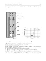
the substrate are as shown in Figure 2.15.
FIGURE 2.14
The refraction of the SU-8 resist may cause the projected light beam to bend over and therefore
leading to reduce angle of the light projection. SU-8’s refraction and the critical angle (critical
angle is about 36.8° at 365 nm).
45°
90°
45° 37.3°
Incident
light
Incident
light
SU-8
SU-8
Air
Air
Refracted lightRefracted light
DK532X_book.fm Page 30 Tuesday, November 14, 2006 10:41 AM
raphy is shown in Figure 2.15. The positions of the prism, mask, SU-8, and
© 2007 by Taylor & Francis Group, LLC
32 Bio-MEMS: Technologies and Applications
(2.10)
The substrate therefore needs to be kept at θ = 45° + θ
7
with the horizontal
level (because the light beam in the UV station is always in the vertical
direction) to completely compensate for the refraction at the interface to
obtain a 45° refractive angle inside the SU-8 photoresist.
2.5.1 Micromixer/Reactor
As an example of tilted lithography of SU-8, we present a novel passive
micromixer/reactor based on arrays of spatially impinging microjets, which
takes a three-dimensional approach in design and is based on a fabrication
process using UV lithography SU-8 photoresist [25].
To mix microvolumes of fluid samples in microfluidic systems is always
a challenging task. Because the flow in all microfluidic systems is laminar
and has a low Reynolds number, diffusion is the dominant mechanism.
Various efforts have been made to improve the mixing process by introduc-
ing geometric irregularities in inflow channels to create localized eddies and
turbulent flows. Efforts have also been made to use special actuation mech-
anisms to disturb the flow with such noncontact measures as ultrasound
waves. Because it is very difficult to obtain high mixing efficiency with a
diffusion mechanism, some reported efforts used active disturbance to create
turbulence in the microfluidic systems. An obvious approach to increased
diffusion efficiency is to maximize the effective interfacial areas of the two
samples to be mixed. According to the scaling law, the most effective way
to maximize the effective surface area of liquid is to convert it into plumes
of stream. This is the approach we have adopted in our design of the micro-
mixer. The micromixer/reactor has a simple structure and significantly
boosts the mixing efficiency by increasing the interfacial contact with the
impinging plumes from two opposite arrays of more, but smaller-sized,
micronozzles.
The micromixer/reactor is based on large arrays of spatially impinged
microjets mixing. The schematic design for the micromixer/reactor is shown
micronozzles are parallel with the substrate plane. There are two possible ways
to arrange the opposite arrays of nozzles: directly opposite orientations or with
a designed offset. The two sample fluids are delivered to inlet A and inlet B,
respectively. Then they are converted into plumes of streams by the large
micronozzle array and driven into the mixing chamber. The mixing processing
is three-dimensional with multiplayer spatially impinged jet arrays. This helps
to enhance the Reynolds number; increase the effective interfacial areas; con-
vert a higher percentage of the kinetic energy into microscopic molecular
θθ=°+45
7
DK532X_book.fm Page 32 Tuesday, November 14, 2006 10:41 AM
in Figure 2.16. Two arrays of micronozzles are in opposite directions. The
© 2007 by Taylor & Francis Group, LLC
34 Bio-MEMS: Technologies and Applications
2.5.2 Three-Dimensional Hydrofocus Component for Microcytometer
Flow cytometric devices are very important for biomedical research and
clinical diagnostics. The labeled cell is driven to flow through a nozzle so
that light scattering or fluorescence measurements can be used for analyses.
Many research efforts have been made to develop microcytometers to reduce
the device and sample sizes, develop low-cost and single-use disposable
devices, and to improve device portability along with low consumption of
sample and buffer fluids, and to reduce the biohazard risk level.
The principle of hydrofocusing in a microchannel is based on laminating
cells with sheath flow [31]. A small volume of sample flow is injected into
a much larger volume of sheath fluid. Both the sheath flow and sample flow
require a small Reynolds number. Most of the reported hydrofocusing units
for microcytometers based on sheath flow are two-dimensional, which only
focuses the samples in the same plane as the substrate. A truly three-dimen-
sional hydrofocusing component can focus the cells along the core stream
to flow with an almost uniform velocity.
Based on the three-dimensional hydrofocusing requirements and the
microfabrication limitations of SU-8 UV lithography, a three-dimensional
hydrofocusing unit for microflow cytometry was designed as shown by the
(a)
(b)
FIGURE 2.17
Schematic fabrication diagram and SEM image of the fabricated micromixer/reactor. (a) Li-
thography principle. (b) SEM image of the prototype mixer.
Array of light beams Array of light beams
DK532X_book.fm Page 34 Tuesday, November 14, 2006 10:41 AM
schematic diagram in Figure 2.19. There are three inlets for the hydrofocusing
© 2007 by Taylor & Francis Group, LLC
36 Bio-MEMS: Technologies and Applications
glass and sloped bottom help focus the flow upward to a central region in
the direction perpendicular to the substrate. The left-side slope, right-side
slope, and the two sloped sidewalls perpendicular to the substrate assist in
achieving flow to the central region in a horizontal direction [31].
In the fabrication process, all the slopes and the sample injection holes
were fabricated using tilted exposure. A total of three exposures were
required: (1) a 60° angle tilt exposure to achieve slopes having a 30° angle
with the substrate, (2) a 45° angle tilt exposure to obtain a suspended sample
injection nozzle in the center position of the sample inlet end, and (3) a
conventional contact exposure to produce all of the SU-8 sidewalls.
The fabrication procedures were as follows: clean the Si or glass substrate;
spin-coat SU-8 100 photoresist to obtain a 500 µm–thick resist layer; soft
bake the sample; conduct a 60° tilted exposure of SU-8 with the help of a
prism and optical liquid for refraction compensation to obtain slopes tilted
at 30° with the substrate; postbake the sample; spin-coat SU-8 100 photore-
sist to obtain the second 500 µm–thick resist layer; prebake the sample; use
a 45° angle tilted exposure of the SU-8 with a correction prism and optical
liquid to obtain a suspended sample injector nozzle in the center of the
sample inlet end; expose all of the SU-8 sidewalls; postbake the sample;
develop with SU-8 developer; bond cover glass, seal inlet and outlet tubes.
Figure 2.20 shows three SEM images of a prototype hydrofocusing unit
fabricated using the tilted lithography method.
The three-dimensional focusing function of the prototype hydrofocusing
show experimental results that clearly demonstrated the three-dimensional
hydrofocusing function. The main advantages of this polymer hydrofocusing
FIGURE 2.20
SEM pictures for the three-dimensional hydrofocusing components.
Sheath
flow inlet
Sample
flow inlet
Sample
injection
nozzle
Sloped
sidewall
Center
slope
Outlet
Sample
injection
nozzle
DK532X_book.fm Page 36 Tuesday, November 14, 2006 10:41 AM
unit was tested using a fluorescent dye solution. The images in Figure 2.21
© 2007 by Taylor & Francis Group, LLC
38 Bio-MEMS: Technologies and Applications
is based on regular lithography and surface technologies. Integrated optical
systems often require the lenses’ principal planes to be perpendicular to the
substrate on which the system is constructed. One approach is to use a flexible
hinge [32,33]. Another is using microstereolithography [34,35].
We reported a method to obtain a quasiparabolic surface for an out-of-
plane prealigned polymer microlens [25–29]. This out-of-plane polymer
microlens can be easily prealigned with other optical components with no
additional adjustment and assembly required, and dramatically reduce the
running cost and improve the quality and performance of the optical system.
The other optical components also can be fabricated by direct lithography
of SU-8. All of the optical components are prealigned with the same optical
axis in mask design, and no changes and adjustments between the mask and
the photoresist are needed during lithography.
The basic fabrication principle for out-of-plane, prealigned polymer refrac-
tive microlenses and microlens arrays can be explained using the schematic
diagrams shown in Figure 2.22. The intersection region as shown in Figure
2.22a was double exposed and formed the lens base. The intersected region
included four pieces of cylindrical surface with sharp edge lines as shown in
Figure 2.22b. The development rate for the unexposed SU-8, single-exposed
SU-8, and double-exposed SU-8 are different. By careful control of the expo-
sure dosage and the optimized development time, the double-exposed region
formed the microlens or microlens array as shown in Figure 2.22c.
using this method. Figure 2.23b shows the focus function of the out-of-plane
microlens and microlens array.
A simple application of the out-of-plane prealigned microlens and micro-
lens array [29] is to design and fabricate an integrated fiber coupler and fiber
bundle couplers. The substrate coated with 1100 µm–thick SU-8 100 was soft
FIGURE 2.22
Combining microstereolithography and thick resist UV lithography for 3D microfabrication.
(a) Two cylindrical beams used to expose the negative resist. Exposed regions are kept and the
unexposed regions removed in development. (b) The intersection region formed by two cylin-
drical beams is doubled-exposed and formed the lens base. (c) After development, the sharp
edges were rounded and a smoother surface profile is obtained.
Unexposed
SU-8
Exposed
SU-8
Ellipse open
Sharp edges
Single-exposed
SU-8 cylinders
Edges
smoothed
Substrate
Double-exposed
region formed
the microlens
Substrate
(a) (b) (c)
DK532X_book.fm Page 38 Tuesday, November 14, 2006 10:41 AM
Figure 2.23a shows an SEM image of a sample microlens array fabricated
© 2007 by Taylor & Francis Group, LLC
40 Bio-MEMS: Technologies and Applications
2.6 Conclusions
In this chapter, we have presented some detailed discussions on optical
lithography of SU-8. Detailed processing tips have been provided. In addi-
tion, we have also presented some theoretical and experimental studies on
air gap effects on the lithography quality of ultrathick SU-8 resist and the
method to compensate for it. The combination effect of diffraction compen-
sation, wavelength selection, and one-direction agitation development is
present by ultra-high-aspect-ratio SU-8 microstructures. SU-8 tilted lithog-
raphy and its application are also presented. Some representative applica-
tions of UV lithography of SU-8 in microfluidics and micro-optics have also
been presented.
The polymer out-of-plane microlens can be fabricated using direct tilted-
lithography of SU-8 resist. The microlens array fabricated this way is perpen-
dicular to the substrate without requiring any assembly or adjustment, and
can be designed to any prealigned positions. With optical components pre-
aligned in mask design, it is possible to have all components integrated onto
a single platform for an optical bench without any assembly or adjustment
required. Unique microfluidic components and systems can also be made
using the direct lithography method as demonstrated by the micromixer and
the hydrofocusing unit for the microflow cytometer presented in this chapter.
References
[1] N. LaBianca, and J. Delorme, High aspect ratio resist for thick film applications,
in Proceedings of the International Society for Optical Engineering (SPIE), 2438,
846–852, 1998.
[2] H. Lorenz, M. Despont, P. Vettiger, and P. Renaud, Fabrication of photoplastic
high-aspect ratio microparts and micromolds using SU-8 UV resist, Microsyst.
Technol. 4, 143–146, 1998.
[3] K. Lee, N. LaBianca, S. Rishton, and S. Zohlgharnain, Micromachining appli-
cations for a high resolution ultrathick photoresist, J. Vac. Scien. Technol. B 13,
3012–3016, 1995.
[4] H. Lorenz, M. Despont, N. Fahrni, N. Labianca, P. Vettiger, and P. Renaud,
EPON SU-8: A low-cost negative resist for MEMS, in Proc. of Micro Mechanics
Europe '96, Barcelona, 32–35, 1996.
[5] H. Lorenz, M. Laudon, and P. Renaud, Mechanical characterization of a new
high-aspect-ratio near UV-photoresist, Microelec. Engin. 41/42, 371–374, 1998.
[6] J. Williams and W. Wang, UV-LIGA fabrication of electromagnetic power micro-
relays, presented at the International Symposium on Test and Measurement
(ISTM/2001), Shanghai, China, June 2001.
[7] C. Oropeza, K. Lian, and W. Wang, “Fracture toughness study on LIGA fabri-
cated microstructures,” presented in Micromachining and Microfabrication, Pho-
tonics West, San Jose, California, January 2003.
DK532X_book.fm Page 40 Tuesday, November 14, 2006 10:41 AM
© 2007 by Taylor & Francis Group, LLC
UV Lithography of Ultrathick SU-8 41
[8] D. E. Lee, H P. Chen, S. Soper, and W. Wang, An Electrochemical Micropump
and Its application in a DNA Mixing and Analysis System, presented in
Micromachining and Microfabrication, Photonics West, San Jose, California, Jan-
uary 2003.
[9] R. Yang, S. J. Jeong, and W. Wang, UV-LIGA microfabrication of a power relay
based on electrostatic actuation, presented in Micromachining and Microfabrica-
tion, Photonics West, San Jose, California, January 2003.
[10] K H. Hang, W. Wang, M. C. Murphy, and K. Lian UV-LIGA microfabrication
and test of an AC type micropump based on magnetohydrodynamic (MHD)
principle, in Proceedings of the SPIE Symposium on Microfabrication, Santa Clara,
CA, 20–22 September, 2000.
[11] Y. Konaka and Mark G. Allen, Single and multi-layer electroplated microaccel-
erometers, in Proceedings of the IEEE Micro Electro Mechanical Systems (MEMS),
168–173, 1996.
[12] H. Lorenz, M. Despont, N. Fahrni, J. Brugger. P. Renaud, and P. Vettiger, High
aspect ratio ultrathick, negative-tone near-UV photoresist and its applications
for MEMS, Sensors and Actuators A, A 64, 33–39, 1998.
[13] L. Dellmann, S. Roth, C. Beuret, L. Paratte, G A. Racine, H. Lorenz, M. Despont,
P. Renaud, P. Vettiger, and N. de Rooij, Two steps micromoulding and photo-
polymer high-aspect ratio structuring for applications in piezoelectric motor
components, Microsyst. Technol. 4, 147–150, 1998.
[14] H. Chang and Y. Kim, UV-LIGA process for high aspect ratio structure using
stress barrier and C-shaped etch hole, Sensors and Actuators A: Physical, 84,
342–350, 2000.
[15] Z. Ling, K. Lian, and L. Jian, Improved patterning quality of SU-8 microstruc-
tures by optimizing the exposure parameters, Proceedings of the International
Society for Optical Engineering (SPIE), 3999, P1019–1027, 2000.
[16] J. O’Brien, P. J. Hughes, M. Brunent, et al., Advanced photoresist technologies
for microsystems, J. Micromech. Microeng., 11, 353–358, 2001.
[17] J. Zhang, K. L. Tan, G. D. Hong, L. J. Yang, and H. Q. Gong, Polymerization
optimization of SU-8 photoresist and its applications in microfluidic systems
and MEMS, J. Micromech. Microeng., 11, 20–26, 2001.
[18] C. Lin, G. Lee, B. Chang, and G. Chang, A new fabrication process for ultrathick
microfluidic microstructures utilizing SU-8 photoresist, J. Micromech. Microeng.,
12, 590–597, 2002.
[19] P. M. Dentinger, K. L. Krafcik, K. L. Simison, R. P. Janek, and J. Hachman, High
aspect ratio patterning with a proximity ultraviolet source, Microelectronic En-
gineering, 61–62, P1001–1007, 2002.
[20] J. Williams and W. Wang, Study on the postbaking process and the effects on
UV lithography of high aspect ratio SU-8 microstructure,” J. Microlith., Micro-
fab., Microsyt., in press.
[21] R. Yang and W. Wang, Application of optical refractive index liquid and wave-
length selection for ultra-high-aspect-ratio UV-lithography of thick SU-8 re-
sist,” Sensor and Actuator B: Chemical, 110/2, 279–288, 2005.
[22] Y. J. Chuang, T. G. Tseng, and W. K. Lin, Reduction of diffraction effect of UV
exposure on SU-8 negative thick photoresist by air gap elimination, Microsystem
Technologies, 8, 308–313, 2002.
[23] E. Reznikova, V. Namov, and J. Mour, Deep photo-lithography characterization
of SU-8 resist layers, Microsystem Technologies, 11, 4–5, 282–291, 2005.
DK532X_book.fm Page 41 Tuesday, November 14, 2006 10:41 AM
© 2007 by Taylor & Francis Group, LLC
42 Bio-MEMS: Technologies and Applications
[24] S.J. Lee, W. Shi, P. Maciel, and S.W. Cha, Top-edge profile control for SU-8
structural photoresist, in Proceedings of 15th Biennial University/Government/In-
dustry Microelectronics Symposium, 389–390, June 30–July 2, 2003, Boise, ID.
[25] R. Yang, J. D. Williams, and W. Wang, A rapid micro-mixer/reactor based on
arrays of spatially impinging micro-jets, Journal of Micromechanics and Microengi-
neering, 14, 10, 1345–1351, October 2004.
[26] R. Yang and W. Wang, Fabrication of out-of-plane SU-8 refractive microlens
using directly lithography method, SPIE Photonics West, San Jose, CA., Pro-
ceedings of the International Society for Optical Engineering (SPIE), 5346, 2004,
151–159, 2004.
[27] R. Yang and W. Wang, Out-of-plane polymer refractive microlens fabricated
based on direct lithography of SU-8, Sensor and Actuators A: Physical, 113, 1,
P71–77, June 15, 2004.
[28] R. Yang and W. Wang, Numerical and experimental study on an out-of-plane
pre-aligned refractive microlens fabricated using UV lithography method, Op-
tical Engineering, 43, 12, 3096–3103, December 2004.
[29] R. Yang, S. Soper, and W. Wang, Out-of-plane microlens array fabricated using
ultraviolet lithography,” Applied Physics Letter, 86, 16, 161110-1–161110-3, April
2005.
[30] R. Yang, S. A. Soper, and W. Wang, Microfabrication of pre-aligned fiber bundle
couplers using ultraviolet lithography of SU-8, Sensors and Actuators, A, 127, 1,
123–130, February 28, 2006.
[31] R. Yang, D. L. Feeback, and W. Wang, Microfabrication and test of three-
dimensional polymer hydro-focusing unit for flow cytometry applications,
Sensors and Actuators A: Physical, 118, 2, 259–267, February 2005.
[32] C.R. King, L.Y. Lin, and M.C. Wu, Out-of-plane refractive microlens fabricated
by surface micromachining, IEEE Photonics Technology Letters, 8, 10, 1349–1351,
October 1996.
[33] Yong W. Yi and Chang Liu, Assembly of micro optical components using
magnetic actuation, Sensors and Actuators A, 78, P205–211, 1999.
[34] K. Ikuta, S. Maruo, and S. Kojima, New micro stereo lithography for freely
movable 3D micro structure, Proceedings of MEMS98, Heidelberg, Germany.
1998.
[35] A. Bertsch, H. Lorenz, and P. Renaud, 3D microfabrication by combining mi-
crostereolithography and thick resist UV lithography, Sensors and Actuators: A-
Physical, 73, 1–2, 14–23, 1999.
DK532X_book.fm Page 42 Tuesday, November 14, 2006 10:41 AM
© 2007 by Taylor & Francis Group, LLC
43
3
The LIGA Process: A Fabrication Process
for High-Aspect-Ratio Microstructures
in Polymers, Metals, and Ceramics
Jost Goettert
CONTENTS
3.1 The LIGA Process: A Brief History 44
3.2 The LIGA Process: A Brief Introduction 45
3.3 Deep X-Ray Lithography Process 46
3.3.1 Synchrotron Light, Beamlines, and Scanner 46
3.3.2 X-Ray Mask 49
3.3.3 Resist Application and X-Ray Exposure 52
3.4 High-Aspect-Ratio LIGA Structures 56
3.4.1 Electroplating of DXRL Microstructures 59
3.4.1.1 Basic Principle of Electrodeposition 59
3.4.1.1.1 Galvanostatic and Potentiostatic
Plating 60
3.4.1.2 Electroplating Rate and Calculation of the
Deposition Thickness 61
3.4.1.2.1 Surface Uniformity of Electroplated
Metals 62
3.4.2 Nickel Electroplating and Solutions 63
3.4.3 Electroplating Quality and Influential Factors 64
3.4.3.1 Internal Stress 64
3.4.3.1.1 Current Density 64
3.4.3.1.2 Temperature 65
3.4.3.1.3 pH Value 65
3.4.3.1.4 Agitation 65
3.4.3.1.5 Filtration 65
3.5 Molding of LIGA Microstructures 66
3.6 Application of LIGA Microstructures 70
3.6.1 Mold Insert Fabrication 71
DK532X_book.fm Page 43 Friday, November 10, 2006 3:31 PM
© 2007 by Taylor & Francis Group, LLC
The LIGA Process 47
that describes the photon energy at which the power spectrum is divided in
half. The basic properties of the light source can be calculated from Equations
3.1 through 3.3 [16]:
Total energy loss per revolution
(3.1)
Characteristic energy and wavelength, respectively, of the emitted synchro-
tron spectrum
, (3.2)
Vertical opening angle of the emitted light cone
(3.3)
For example, using Equation 3.3 the vertical beam width for the CAMD
(Center for Advanced Microstructures and Devices at Louisiana State Univer-
sity (LSU) in Baton Rouge, Louisiana) storage ring (electron energy = 1.3 GeV)
is calculated to approximately 0.4 mrad resulting in a typical vertical Gaussian
intensity distribution of 4 mm full width half maximum (FWHM) at the mask-
resist plan at a distance of approximately 10 m from the source point.
In the 1970s, the use of synchrotron radiation as a short wavelength light
source was already being intensively discussed for lithographic patterning
of small microelectronic circuits [17,18]. X-ray lithography was a serious
contender for the next generation lithography (NGL) and dedicated compact
synchrotron light sources like HELIOS 1 [19] designed by Oxford Instru-
ments were built and operated successfully [17]. In the early 1980s a second
property of x-rays—their large penetration depth into matter—was then
TABLE 3.1
Important Properties of Synchrotron Radiation
Continuous light spectrum ranging from the infrared to the hard x-rays
High intensity
High degree of collimation (nearly parallel light)
Clean environment—light is generated inside an ultrahigh vacuum system
High stability of intensity and source position ensuring predictable experimental parameters
Long beam lifetime (more than 10 hours) allowing experiments with quasi-constant conditions
Well-defined structure enabling time-resolved spectroscopy and imaging experiments
PkW
EGeV
rm
IA[] .
[]
[]
[]= 88 5
4
0
EeV
EGeV
rm
c
[]
[]
[]
= 2218
3
0
λ
c
GeV
[
[]
Å] 5.59
r[m]
E
0
3
=
Ψ ~.
[]
1
51 10
1
0
2
4
γ
==
−
mc
E
x
EGeV
DK532X_book.fm Page 47 Friday, November 10, 2006 3:31 PM
© 2007 by Taylor & Francis Group, LLC
48 Bio-MEMS: Technologies and Applications
considered for patterning of tall structures using deep x-ray lithography
(DXRL) shadow printing [20]. This initial effort grew to the point that today
a number of dedicated synchrotron radiation facilities worldwide provide
easy access and sufficient beamtime for many users from academia and
industry, enabling continuous process improvement and commercial use
[21–24].
CAMD at LSU in Baton Rouge, LA, is one of these dedicated synchrotron
radiation facilities with a strong program in LIGA technology [25]. The ring
delivers light from 8 bending magnets as well as one insertion device—a 7-
Tesla superconductive wiggler—to its users, and four microfabrication
beamlines offer a large variety of patterning opportunities using soft and
hard x-rays. The exposure spectra for the bending magnet and wiggler
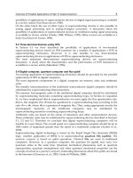
sources are shown in Figure 3.2, representing typical light spectra used for
x-ray lithography.
line at a synchrotron light source. The ultrahigh vacuum x-ray beamline is
directly attached to the vacuum system of the electron storage ring. A number
of safety components including gate valves, a fast-closing shutter, and pho-
ton- and Bremsstrahlungs-shutters ensure both a vacuum- and radiation-safe
operation of the beamline. The beamline is terminated by an exposure station
or x-ray scanner. The x-ray scanner in its simplest design consists of a vacuum
chamber and houses a linear motion stage that moves the mask or substrate
assembly vertically across the narrow, collimated synchrotron beam. By using
FIGURE 3.2
Power output for an average current of 100 mA as a function of photon energy for different
CAMD source points and wiggler operating conditions. The low energy part of the “white
spectra” is typically absorbed by a vacuum window made from beryllium resulting in photon
energies of the exposure spectrum ranging from 2 keV to 40 keV.
100 1000 10000
0.0
0.1
0.2
0.3
0.4
0.5
Power (mW/mrad/100 mA)
Photon energy (eV)
Bending magnet
Wiggler, 5T
Wiggler, 7T
DK532X_book.fm Page 48 Friday, November 10, 2006 3:31 PM
Figure 3.3 illustrates the schematic setup of an x-ray micromachining beam-
© 2007 by Taylor & Francis Group, LLC
50 Bio-MEMS: Technologies and Applications
using high-atomic-number material, typically gold, forming the absorber
pattern. The thickness of the gold absorber ranges from a few micrometers
when using soft x-ray photons (1 to 4 keV photon energy) up to 50 µm and
more when using hard x-ray photons (50 keV) [26]. Due to this wide range
of photon energies as well as different specifications regarding resist thick-
ness, resolution, and structure tolerances, no standard mask fabrication pro-
cess exists, but individual solutions are used [27–32].
(a)
(b)
FIGURE 3.4
(a) DEX 03 scanner inside the radiation hutch at the CAMD XRLM 4 beamline. (b) DEX 02
scanner inside the radiation hutch at the CAMD XRLM 1 beamline.
DK532X_book.fm Page 50 Friday, November 10, 2006 3:31 PM
© 2007 by Taylor & Francis Group, LLC
The LIGA Process 51
Mask fabrication combines a number of techniques starting with electron
or photon or laser beam writing of the initial design onto a chromium or
optical mask substrate. The optical mask will then be transferred into a thick
optical resist, for example up to 70 µm–thick SU-8, using optical lithography
(Figure 3.5a) [32]. After exposure, baking, and development, the resist struc-
ture is used as a template and the open areas are filled with gold by electro-
plating. Resist removal and mask mounting onto a support ring completes
the process. Masks fabricated with this rapid prototyping approach have,
typically, the smallest feature sizes of 8 µm for a 15 µm–thick resist, which
will increase with thicker resist layers. Short mask fabrication times of
approximately 3 days is attractive for performing initial exposure tests and
is commonly practiced when exploring new designs.
For designs with smaller critical dimensions, the optical lithography is
done into a thinner, positive resist (3 to 10 µm thick) and after development
approximately 2 to 6 µm–thick gold is electroplated into this template (Figure
3.5b) resulting in the so-called x-ray intermediate mask. Using soft x-rays
from a mirror beamline, the pattern is then transferred into a thicker positive
resist, for example, 10 to 80 µm PMMA. After development and gold elec-
troplating, a so-called x-ray working mask is completed containing very fine,
micrometer-sized structures. Typical fabrication time for working masks is
2 weeks with significantly higher costs compared to the rapid prototyping
approach but also superior critical dimensions.
For even smaller, submicrometer critical dimensions, high energy electron
beam lithography (100 keV) has to be employed directly into 2 to 3 µm–thick
electron beam resist. After development, this pattern serves as a template
for gold electroplating resulting in the x-ray intermediate mask, which will
then be transferred with soft x-ray into the final working mask, similar to
FIGURE 3.5
(a) Optical lithography and gold plating used to fabricate x-ray masks with critical dimensions
down to 10 µm. (b) A combination of optical and soft x-ray lithography with subsequent gold
plating is used to fabricate x-ray masks with critical dimensions down to 2 µm.
Optical mask
Intermediate
x-ray
mask
Working x-ray mask
Soft x-ray lithography
(a) (b)
DK532X_book.fm Page 51 Friday, November 10, 2006 3:31 PM
the process scheme illustrated in Figure 3.5b. Figures 3.6a through 3.6c show
© 2007 by Taylor & Francis Group, LLC