Bio-MEMS Technologies and Applications - Wang and Soper (Eds) Part 7 ppt
Bạn đang xem bản rút gọn của tài liệu. Xem và tải ngay bản đầy đủ của tài liệu tại đây (290.24 KB, 15 trang )
177
7
Micromixers
D. E. Nikitopoulos and A. Maha
CONTENTS
7.1 Introduction 177
7.2 Some Basic Considerations 178
7.3 Passive Micromixers 181
7.3.1 Pressure-Driven Passive Micromixers 181
7.3.2 Electrically Driven Passive Micromixers 185
7.4 Active Micromixers 188
7.5 Multiphase Micromixers 191
7.6 Performance Metrics for Microscale Mixer Design
and Evaluation 192
7.7 Design Methodology for Optimal Diffusion-Based, Micromixers
for Batch Production Applications 195
References 206
7.1 Introduction
The topic of mixing on the microscale has been at the forefront of research
and development efforts over roughly the last fifteen years since the tech-
nological thrust toward miniaturization of fluidic systems began. Mixing is
of significant importance to realizing lab-on-a-chip microscale reactors and
bioanalysis systems because the reactions carried out on the micro- or even
nanoscale in such devices require the on-chip mixing of samples and
reagents. Typical application class examples are thermal-cycling reactors for
the popular polymerization chain reaction (PCR)
1,2
and the Ligase chain
reaction (LCR)
3
as well as other similar applications. Fully integrated microf-
luidic chips performing such reactions require modestly fast mixing in batch
mode, should the mixing be performed on-chip. This is so because the
DK532X_book.fm Page 177 Tuesday, November 14, 2006 10:41 AM
© 2007 by Taylor & Francis Group, LLC
Micromixers 179
combustion systems, chemical reactors, etc.). Turbulent flows are character-
ized by large Reynolds numbers, Re = UD/ν, where, U, is a velocity scale
representative of the process, D is a length scale and, ν is the kinematic
viscosity (or momentum diffusion coefficient) of the fluid. In microfluidic
systems the length scales are of micron order (e.g., ranging from 1 mm to
500 mm), and because in bioanalytical applications the fluids are predomi-
nantly aqueous solutions, the kinematic viscosity is on the order of 10
6
m
2
/s.
The transition Reynolds number from laminar to turbulent flow is approxi-
mately 2300 for ducts and channels, so in order to have the benefit of fully
developed turbulent flow, the Reynolds number ought to be higher than
that. The critical Reynolds numbers for other flows, such as jets and free
shear layers, are also on the order of several hundreds. If one wishes to
generate turbulent flow (e.g., Re = 5000) in a microchannel 100 µm by 100 µm
in cross-section, one requires a velocity of approximately 48m/s. At this
velocity the pressure drop in the channel is more than 4 atmospheres per
millimeter of length, which is prohibitive. Other than examining the feasi-
bility of turbulent microflow, the example brings forth the fact that in addi-
tion to the requirement of rapid and effective mixing, one has to be vigilant
with respect to the required pressure to drive the microfluidic chip. High
pressure requirements are undesirable because they require on-chip, micro-
pumping devices able of sustaining them, which at present do not exist. In
addition they impose higher loads on microfluidic chip components and
make it more prone to leakage if not breakage and/or debonding of bonded
surfaces. Increasing the microchannel cross-section alleviates the high pres-
sure requirement, but increases the volume of the device. Nevertheless, in
the above example, if one uses a 500 µm by 500 µm channel, the pressure
drop per unit length of channel for the same Reynolds number is reduced
by two orders of magnitude, but the volume of the channel is increased by
a factor of 25. Larger chip volume translates into larger amounts of samples
and reagents and to some extent negates part of the advantage of reducing
bioanalytical processes to the microscale. The example highlights the fact
that chip volume is yet another parameter one needs to be vigilant about.
In conclusion, turbulent flow on the microscale for the benefit of achieving
effective mixing is not out of the question, but its usefulness is limited
because of pressure drop and chip-volume constraints. It is perhaps not
surprising that to the extent of the author’s awareness, the highest Reynolds
number reported for the operation of a micromixer in the micromixing
literature is laminar (500),
4
well below the transition to turbulence value,
with still a rather high pressure drop of approximately 0.47 atmospheres
per millimeter of length. This mixer was a simple T-junction type fabricated
in silicon and covered by Pyrex glass. It should be noted that in Wong et
al.,
4
very fast mixing was demonstrated at this value of the Reynolds number
caused by instability in the shear layer formed at the interface of the mixed
streams in a low-aspect-ratio channel (0.5) with a hydraulic diameter of
67 µm, but required a pressure of almost 5.5 atmospheres, which is its major
operational drawback.
DK532X_book.fm Page 179 Tuesday, November 14, 2006 10:41 AM
© 2007 by Taylor & Francis Group, LLC
180 Bio-MEMS: Technologies and Applications
In the absence of turbulent transport, the only recourse to achieving effec-
tive mixing is the reduction of the molecular diffusion length. This follows
from basic dimensional considerations because the time required to achieve
full mixing is the diffusive time, t
D
= δ
D
2
/D
12
, necessary for the concentration
signal to traverse a length, δ
D
. When the mass diffusion coefficient is very
small (<O [10
–10
m
2
/s]) the only way to cut down on the mixing time is to
reduce this diffusion length. Almost all efforts to improve mixing perfor-
mance on the microscale strive to achieve this by employing a wide variety
of means. For example, the so-called lamination micromixers
5
pursue the
creation of several alternating narrow layers of the compounds to be mixed,
so as to cut down on the diffusion length; micromixers based on chaotic
advection (chaotic stirring)
6,7,8
pursue the same goal by kinematically folding
the interfaces between the compounds multiple times; a broad variety of
micromixers achieve the same through the use of time-varying external
perturbations or exploiting instability mechanisms.
Much like other devices, micromixers are traditionally classified as
active or passive depending on whether or not an external energy source
is used other than that driving the flow through the device. Although
active mixers may effectively provide rapid mixing, it cannot be denied
that the additional mechanical and electronic devices, both on- and off-
chip, often add undesirable complexity. These additional devices need
extra energy, space, and if on-chip, may also be difficult to fabricate and
integrate to form a cost-effective and compact lab-on-a-chip. Additionally,
electrical fields and heat sometimes generated by active control may dam-
age biological samples.
9
Different methods and substrates have been used
to fabricate both active and passive micromixers, but it is generally agreed
that passive mixers are most often easier to fabricate and simpler in design
than active mixers. This is more so for pressure-driven devices than elec-
trically driven ones.
Several reviews of micromixers have appeared, especially during recent
years, and we will mention a few. A brief review of passive and active
micromixers can be found in Campbell and Grzybowski
10
who also provide
a tabulated assessment of performance and manufacturing complexity of a
few mixers, but focus their discussion on self-assembled magnetic micromix-
ers. Passive micromixers were recently reviewed in Hardt et al.
11
A more
comprehensive and nicely illustrated review of a broad variety of both pas-
sive and active mixers available in the literature is presented in Nguyen and
Wu
5
and will not be duplicated herein. However, an overview with repre-
sentative examples of micromixers from each class will be given here for the
benefit of the reader. An overview will be given for passive, active and
multiphase flow mixers, the former organized in terms of the driving force
used to generate the main flow through the device, as appropriate. The last
category (multiphase) is discussed separately, although it contains micro-
mixers from both of the other categories, in order to emphasize that the
related devices involve an auxiliary passive fluid and moving interfaces.
DK532X_book.fm Page 180 Tuesday, November 14, 2006 10:41 AM
© 2007 by Taylor & Francis Group, LLC
182 Bio-MEMS: Technologies and Applications
of which is specific to their mixer configuration, and reduced dead time by
a factor of approximately eight relative to the previously mentioned capil-
lary-based mixers, by optimizing focusing. The hydrodynamic focusing con-
cept was used with equal success by Pabit and Hagen,
17
who employed
coaxial, UV-transparent, fused silica capillaries (20 µm ID in 100 mm ID) to
achieve off-chip rapid mixing for fast kinetic studies using UV-excited fluo-
rescence probes. The hydrodynamic focusing effect also contributed to effi-
cient solvent extraction by Hibara et al.,
18
who generated a multilayer flow
of miscible and immiscible fluids in 70 µm–wide channels of low aspect ratio
(0.43) using a focusing Ψ-junction configuration in combination with a down-
stream Ψ-junction one. Although achieving rapid mixing was not their objec-
tive, their simple, single-manufacturing-layer, glass device, could be
operated as a micromixer.
A Ψ-junction mixer realized in silicon and featuring
a contraction upstream and an expansion downstream of the mixing channel
was developed by Veenstra et al.
19
With a modest aspect ratio (2), they
achieved improved mixing at a low Reynolds number (0.23) and essentially
provided an indication of how an increased aspect ratio can reduce mixing
time or reduce pressure drop. Y-junction micromixers have been successfully
employed by Wu et al.
20
to study nonlinear diffusive mixing in microchan-
nels. Interested in gas mixing, Gobby et al.
21
performed numerical simula-
tions at low Reynolds numbers studying the characteristics of Ψ- and T-
junction micromixers with and without throttling downstream of the mixing
point. They concluded that mixing in gases is improved with throttling and
with modest increases in mixing channel aspect ratio (3). A two-wafer, mul-
tistream (10) mixer with a contraction into a high-aspect-ratio (8) mixing
channel was developed by Floyd et al.
22
on a silicon chip through the use of
deep reactive ion etching (DRIE). This mixer, which was integrated with a
heat exchanger and a probing region to perform infrared transmission kinet-
ics studies of liquid reactions, yielded fully mixed product in a few tens of
milliseconds at a modestly high Reynolds number (97). Considering that
the estimated pressure drop is very modest, this type of mixer is promising
for bio-analytical applications, although the two-wafer alignment and costly
DRIE requirement in its manufacture cannot be overlooked. Various two-
and three-stream high-aspect-ratio (6) micromixers were evaluated through
numerical simulations by Maha et al.
23
in terms of pressure drop and mixing
performance for batch operation. It was shown that a combination of high-
aspect-ratio narrow channels combined with hydrodynamic focusing and
an optimization design scheme for batch mixture production can reduce
mixture production time by an order of magnitude for a fixed pressure drop
requirement, or reduce pressure drop by several orders of magnitude for a
fixed mixture production time relative to unitary aspect ratio counterpart
mixers. This was demonstrated experimentally by Maha
24
for such micro-
mixers hot embossed on polymethylmethacrylate (PMMA) and polycarbon-
ate (PC) polymers using micromilled brass mold inserts. The simple
manufacturing process, capacity for inexpensive mass production and inte-
grability of such polymer mixers make them very good candidates for
DK532X_book.fm Page 182 Tuesday, November 14, 2006 10:41 AM
© 2007 by Taylor & Francis Group, LLC
Micromixers 183
integration into disposable polymer microchips to perform a variety of bio-
assays. A very low aspect ratio (0.012), Ψ-junction glass micromixer was
developed by Holden et al.
25
to simultaneously produce mixtures of quasi-
continuously varying concentrations. This was elegantly achieved by an
array of exit channels connected with their entrances arranged diagonally
over the span of the mixing channel. Up to eleven discretely different con-
centrations were produced simultaneously. A tilted UV lithography tech-
nique was used by Yang et al.
26
to fabricate a micromixer on SU-8 incorpo-
rating opposing arrays of staggered spatially distributed impinging microjets
in a T-junction mixer channel. This novel and rare three-dimensional mixer
on a single layer is readily integrable on SU-8 chips.
A number of micromixers have been designed and realized incorporating
passive elements, which can generate secondary flows, to fold the fluid
interfaces and improve local diffusional mixing by cutting down the diffu-
sion length. Introduction of such elements also results in a pressure drop
overhead because of increased dissipation. So it is useful to put the relevant
designs in this perspective when evaluating their performance, if pressure
drop information is available, which is rarely the case. Most of the micro-
mixers incorporating secondary flow–generating elements can be viewed as
stirring devices often involving chaotic advection mechanisms.
It is well known that bends in channels generate secondary flows at mod-
estly high, to high Reynolds numbers in the laminar regime. This has been
employed by several investigators and mixers with bends have been used
in integrated chips.
27
The same principle, augmented by elastic-fluid insta-
bilities, was also demonstrated to be effective in improving mixing on the
microscale by Pathak et al.
28
for non-Newtonian fluids in low-aspect-ratio
serpentine microchannels. Arrays of modest-aspect-ratio (2) single-level, ser-
pentine (zigzag) microchannels combined with simple Ψ-junction mixers
were introduced and used by Kamidate et al.,
29
and more recently by Lin et
al.,
30
to successfully generate, in a predictable manner, dynamically con-
trolled spatial and temporal concentration gradients on glass-covered poly-
dimethylsiloxane (PDMS) microchips embossed using silicon mold inserts.
A numerical study by Mengeaud et al.
31
indicates that successive bends in
serpentine (zigzag) channels improve mixing at high Reynolds numbers
(O[10
2
]), and that increasing the number of bends per unit length of channel
while holding its width constant, can be detrimental to the mixing enhance-
ment. Their results should be put in perspective of the fact that their simu-
lations were two-dimensional, while in such flows 3-dimensional effects
could be substantial. A passive, single-layer micromixer incorporating com-
plex Tesla structures has been demonstrated by Hong et al.
32
in a cyclo-olefin-
copolymer (COC), low-aspect-ratio (0.45) microchannel fed by a T-junction.
The structures are essentially a combination of a serpentine channel with
curved walls and wedgelike obstacles. Improved mixing was realized with
this device and attributed to Coanda effects in the curved parts of the channel
requiring a modest Reynolds number (6), which is the lowest among the
single-layer passive microchannel mixers with bends.
DK532X_book.fm Page 183 Tuesday, November 14, 2006 10:41 AM
© 2007 by Taylor & Francis Group, LLC
184 Bio-MEMS: Technologies and Applications
Three-dimensional (two-level), serpentine, microchannels of low aspect
ratio (0.5) fed by a T-junction were introduced by Liu et al.,
33
who demon-
strated faster and more complete mixing at modestly high Reynolds numbers
(up to 75) compared to single-level serpentine and straight channel counter-
parts. Standard silicon manufacturing technology was used to realize the 3-
dimensional design, which required a two-wafer process and resulted in
channels of trapezoidal cross-sections. A similar 3-dimensional two-layer
design, realized in PDMS by Park et al.,
34
also incorporated rounded channel
walls to induce rotation in addition to the bend-induced secondary flows
and a splitting and recombination scheme similar to that of Schwesinger et
al.
14
This design realized improved mixing performance for Reynolds num-
bers in the 1 to 50 range. A multilevel 3-dimensional micromixing device of
vascular tortuosity was developed and demonstrated by Therriault et al.
35
incorporated the effects of bends and flow splitting and recombination on
numerous levels, and displayed significant mixing effectiveness improve-
ment over a broad Reynolds number range (greater than 1). This improve-
ment was shown to increase almost exponentially with the Reynolds number.
Putting the added complexity of a multiple layer process aside and the
potentially increased dead volume, the two- and multilayer designs men-
tioned in this paragraph could be good candidates for batch production
micromixers.
Improved mixing has also been realized through the use of grooved chan-
nels as generators of secondary flows. In one of the earliest works, Stroock
et al.
36
took advantage of chaotic advection generated by secondary flows in
low-aspect-ratio (0.35) microchannels bearing angled or herringbone-pat-
terned grooves on the bottom surface and demonstrated significant mixing
improvement relative to the ungrooved channel baseline. Their glass-cov-
ered, Y-junction mixer microchannels were embossed in PDMS using a mold
insert fabricated by a two-layer photolithography process on SU-8. About
the same time, Johnson et al.
37
also demonstrated mixing improvements in
low-aspect-ratio (0.43) T-junction mixer microchannels stamped in polycar-
bonate (PC) with laser-ablated angled grooves on their bottom surface. A
computational parametric study was conducted by Wang et al.
38
on the
performance of grooved mixing channels; they concluded that the minimum
length to generate a single recirculation in the channel depends exponentially
on the groove aspect ratio and is relative independent of velocity. In an other
numerical study, Liu et al.
39
revealed that at low Reynolds numbers (1), both
the 3-dimensional serpentine channel mixer (e.g., as in Liu et al.
33
) and the
one employing a herringbone groove pattern on the channel wall (e.g., as in
Stroock et al.
36
) perform comparably, while at a higher Reynolds number (10)
the serpentine design maintains its performance while the one with the
herringbone grooves does not. Nevertheless, added manufacturing complex-
ity and added dead volume notwithstanding, grooved channels have been
proven to be effective means for enhancing mixing on the microscale in low-
aspect-ratio microchannels at low to modest Reynolds numbers. They could
DK532X_book.fm Page 184 Tuesday, November 14, 2006 10:41 AM
© 2007 by Taylor & Francis Group, LLC
186 Bio-MEMS: Technologies and Applications
mixing performance was improved by approximately an order of magnitude
relative to a reference Y-junction electroosmotically driven mixing channel.
A variety of chamber-based electroosmotic mixers were proposed by Yager
et al.
47
relying on recirculations generated by pressure gradients imposed by
the conservation of mass. The simplest realization of the device involves a
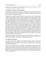
microscale mixing channel with electrodes (A and B) at each end as in Figure
7.1a. When a potential difference is applied between electrodes A and B, the
fluid will be set into motion near the wall region with a velocity in proportion
to the electroosmotic mobility of the wall material. Because the ends of the
mixing channel (between A and B) cannot be penetrated by the flow, con-
servation of mass will dictate a flow inside the core of the cross-section in
the opposite direction to that near the walls. Thus a recirculating flow will
be established within the mixing channel with shear layers in the proximity
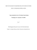
of the walls. This is shown in the numerical simulation results of Figure 7.1
48
for a channel incorporating material nonhomogeneity. The upper part of the
channel has a different elecroosmotic mobility than the lower part. The
resulting recirculating flow field is shown in Figure 7.1 where it is clearly
visible that the fluid is moving in one direction in the proximity of the wall,
while it is moving in the opposite direction in the core. Because of the unequal
mobility of the top and bottom parts of the channel, flow is not symmetrical
with respect to all the geometrical axes of symmetry. The near wall velocity
is higher on the top half compared to the bottom half, and as a result the
return velocity is higher in the lower part of the core. Consequently, the shear
layers on the top half and bottom half are of unequal strengths. The top-to-
bottom asymmetry will be absent if the channel has homogeneous mobility.
This flow is effective in mixing because it folds material lines multiple times
in a short period of time, depending on the potential difference level (88
material lines caused by the recirculating flow, which is responsible for the
effective mixing function. A plug of liquid with a substantially low mass
diffusion coefficient (1.2 10
–10
m
2
/sec) is mixed with a second liquid to form
approximately 40 nL of a 2.78% mixture in less than one second. This illus-
trates the effectiveness of this type mixer.
FIGURE 7.1
Main velocity component contours in chamber electroosmotic micromixer (a) streamwise mid-
plane, x = 0 µm; (b) cross-flow midplane, y = 0 µm.
z
y
x
–2000
–11000
(a) (b)
–9000 –7000 –5000 –3000 –1000 1000 3000 5000 7000 9000 11000 13000
–1000 0
y (mic)
1000 2000
0
150
AB
100
z (mic)
50
z
x
y
–20 0 20
y = 0 mic
0
50
z (mic)
x (mic)
100
150
DK532X_book.fm Page 186 Tuesday, November 14, 2006 10:41 AM
volts in this example). Figure 7.2 illustrates this stretching and folding of
© 2007 by Taylor & Francis Group, LLC
Micromixers 189
pulsations. The same idea has since been considered in a variety of micro-
channel mixers. An early example was that of Volpert et al.
59
Following their
work, pressure pulsations were also used by Deshmukh et al.,
60
who
employed a low-aspect-ratio (approximately 0.2) mixer microchannel with
a T-junction fabricated in silicon using DRIE. An integrated planar micro-
pump was used to pulse the flow in the mixing channel dividing the mixed
liquids into small serial segments and making the mixing process indepen-
dent of convection. A similar device, with a cross-junction and without
integrated pumping, was presented by Lee et al.
61
and was also fabricated
in silicon using DRIE.
The chaotic-advection behavior and associated mixing enhancement of
pulsed flow cross-junction mixers have been studied theoretically by Lee,
62
while Niu and Lee
63
analyzed a multi-cross-junction variant. Pulsations are
in general introduced through the side channels of the cross-junction(s).
Glasgow and Aubry
64
demonstrated numerically and experimentally the
merits of flow pulsation in a T-junction microchannel mixer. Analysis and
realization of pulsed flow T-junction micromixers has been presented more
recently by Tabeling et al.
65
Their micromixer was realized with glass and
PDMS technology and utilized an on-chip microhydraulic actuation system
based on microvalves introduced by Unger et al.,
66
fabricated using their soft
lithography technique. A multi-side-channel (as in Unger et al.
66
), pulsed
flow T-junction mixer was analyzed and evaluated by Bottausci et al.
67
They
concluded that the multiple side-channel design performs better than the
single side-channel one when the pulsations introduced through the side chan-
nels are out of phase. A swirl-chamber mixer micromilled in PMMA was
proposed by Chung et al.
9
in which the swirling of the fluids was achieved by
forward and backward pumping. The mixing chamber was fitted with two
opposing channels of unit aspect ratio tangent to the circular chamber. Simu-
lation indicated up to a twofold mixing improvement compared to that in a
straight channel at rather high, yet laminar, Reynolds numbers (20 to 400). In
general, the majority of the pulsed flow and pressure micromixers are contin-
uous-flow devices and have been shown to improve mixing compared to their
steady-state counterparts leading to shorter mixing-channel lengths for Rey-
nolds numbers of order one or less. When considering such micromixers for
applications, this improvement should be put in perspective of the added
complexity, not so much in terms of manufacturing processes, but that result-
ing from the need for pressure actuation.
Electrical excitation has also been used as an alternative to pressure pulsa-
tions toward improving mixing on the microscale by inducing unsteady sec-
ondary flows and chaotic advection. One of the earliest micromixers utilizing
unsteady electrical fields was that of Lee et al.
61
They demonstrated a pressure-
driven, continuous-flow device with periodic electrical excitation introduced
in a chamber on the flow path. They used a combination of silicon and SU-8
technology to manufacture this low-aspect-ratio (approximately 0.13) active
DK532X_book.fm Page 189 Tuesday, November 14, 2006 10:41 AM
© 2007 by Taylor & Francis Group, LLC
190 Bio-MEMS: Technologies and Applications
mixer. They took advantage of dielectophoretic forces induced by the inho-
mogeneous electrical field to improve mixing of dielectric microparticles.
Shortly after, Oddy et al.
68
presented electrical active mixers based on electro-
kinetic instability excited by sinusoidal oscillations of the electrical filed. They
evaluated a glass-covered PDMS cross-junction mixer and a chamber cross-
junction one very similar to that of Lee et al.
61
in Borofloat glass. The main
flow in both these low-aspect-ratio (0.1 to 0.33) micromixers could be either
pressure or electrically driven. Their measurements proved the concept that
substantial improvement in mixing can be achieved through the exploitation
of electrokinetic instability by applying AC voltages of a few kVolts at frequen-
cies of a few Hz. A T-junction active mixer with an array of electrodes installed
on either side of a unit aspect ratio, mixing channel was successfully demon-
strated by El Moctar et al.
69
Unsteady mixing-enhancing flow is generated due
to EHD instability under the application of steady electrical fields for fluids
that have different electrical properties. This pressure-driven device can also
be operated as an active one by applying an unsteady electrical field, which
further improves mixing performance at low Reynolds numbers (approxi-
mately 0.02). A Ψ-junction and ring-chamber combination active mixer has
been simulated by Chen et al.,
70
and realized by Zhang et al.,
71
on a silicon
chip with integrated heavily doped silicon electrodes. Unsteady electrical
fields imposed in the ring chamber generate secondary flows, which improve
mixing as shown in the simulation results. The device can be pressure or
electrokinetically driven. More recently, Shin et al.
72
conducted an experimental
study of an electrically driven and actuated cross-junction, microchannel mixer
realized on glass. Under a steady driving voltage of a few hundred volts, they
observed instability developing along the focused middle stream with a fre-
quency of a few Hz. Under unsteady conditions with tens of volts peak-to-
peak amplitude, they showed modest mixing enhancement at frequencies
around the first harmonic of the natural instability mode. Active electrically
excited micromixers are attractive for low-flow-rate applications and do not
involve fabrication and operational technological complexity superior to that
required for their passive counterparts, other than an AC generator. Indeed,
they are easier to manufacture than passive mixers employing nonhomoge-
neous charge distributions on microchannel walls. They have the standard
operational drawbacks of electrically driven microfluidic devices.
Magnetic actuation has also been exploited to produce better micromixing
performance. The principle of using magnetohydrodynamic (MHD) forcing to
improve mixing on the microscale was nicely demonstrated by Solomon et al.
73
They performed experiments comparing long-range chaotic mixing of miscible
and immiscible impurities in a time-periodic flow by producing an alternating
magnetic field that generated alternating vortex structures due to MHD insta-
bility. Chaotic advection created by magnetic forces inducing mixing on flows
carrying magnetic microbeads has been demonstrated by Suzuki and Ho
74
and
Suzuki et al.
75
on a low-aspect-ratio serpentine microchannel with a T-junction
and an integrated array of copper electrodes normal to the channel length. A
glass-covered SU-8 channel was created on a silicon substrate in which the
DK532X_book.fm Page 190 Tuesday, November 14, 2006 10:41 AM
© 2007 by Taylor & Francis Group, LLC
Micromixers 193
(7.1)
where A
e
is the area of the exit, or a relevant segment of it; A
i
is the area of
the inlet of the mixing region; c is the local value of the concentration; c
i
is the
concentration of the the i
th
incoming stream inside the mixing channel; and c
∞
is the mixture steady-state concentration. This definition of efficiency is most
adequate when applied locally. For a batch or continuous production micro-
mixer, what really matters is the rate at which the mixed product is produced
at the delivery end of the mixer. Thus, for such mixers, it is important to
evaluate the mixing efficiencies in terms of mass fluxes instead of concentra-
tions. This is necessary because it is possible to have two different mixers with
the same inlet conditions and exit average concentrations, yet with different
velocity profiles across the exit. In such cases, these mixers will produce mixed
product at different rates depending on the distribution of the concentration
relative to the distribution of the velocity. Therefore, it would be more appro-
priate to evaluate the mixing efficiency on the basis of the following definition
introduced by Maha et al.
23
:
(7.2)
where U and r are the local velocity and density, respectively, of the mixture,
and U
i
and r
i
are the velocity and density of the fluid of the i
th
layer. Both of
these definitions can obviously be easily used in numerical simulations of micro-
mixers. The same is not true when carrying out experimental performance
evaluations of micromixers, especially if three-dimensional effects are involved.
The first one can be implemented in an experiment at steady state, or nearly so,
16 36
) to
conduct the evaluation. If three-dimensional effects are not strong, then line-of-
sight averaging observations, such as those obtained from standard fluorescence
microscopy, can also be validly used by replacing the area average in Equation
7.1 by a line average.
38
The definition of Equation 7.2 also requires velocity
measurement over the mixer cross-section, which is a more challenging propo-
sition. The differences between the definition of Equation 7.1 and Equation 7.2
are discussed for diffusion-driven, passive mixers of various types in Maha et
al.
23,24
ar
e observed, which, as expected, are gradually eliminated as the mixture
ε = −
−
−
∞
∞
∫
∫
∑
1
ccdA
ccdA
A
i
A
i
e
i
η
ρ
ρ
= −
−
−
∞
∞
∫
∫
∑
1
Uc c dA
Uc c dA
A
iii
A
i
e
i
DK532X_book.fm Page 193 Tuesday, November 14, 2006 10:41 AM
and illustrated in Figure 7.3. Differences on the order of 5 percentage points
if confocal microscopy is used (see, e.g., Knight et al. and Stroock et al.
© 2007 by Taylor & Francis Group, LLC
196 Bio-MEMS: Technologies and Applications
is not the raw diffusion time but the time it takes for the mixer to deliver
the required volume of fluid and is still measured from the moment the
constituents come in contact with each other. It should be noted that there
might be time overhead associated with the delivery of the mixture constit-
uents to the point of contact, and in a batch delivery micromixer it ought to
be taken into account. Although this time overhead could be influenced by
the particular microscale mixer design, it is reasonable not to include it in
the tally because it may be constrained by other aspects of the microfluidic
chip functionality and the macro–micro interface.
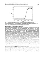
So, for a simple two-compound, batch delivery, microscale mixer consist-
ing of a channel with a width, w, height, H, and length, L, (see Figure 7.4)
the estimate of the mixture production time, t
M
, will have two contributions.
One is , the diffusion time associated with an appropriate diffu-
sion length, δ
D
, and the other is the time, t
P
, required to produce the desired
volume, V, of mixture. The latter is then dictated by the total volumetric flow
rate, Q, since . Thus the estimate of the mixture production time is:
(7.3)
In a microchannel mixer where two or more alternating flow stream layers
are introduced into the mixing channel by means of tributary channels, such
as in Knight et al.
16
(3 tributaries or layers), Hibara et al.
18
(2 and 3 tributaries
or layers), or Floyd et al.
22
(10 tributaries or layers), the relevant diffusion
length is a fraction of the total width of the mixer channel and also depends
on the flow rate of each merging stream. In general, it is safe to select
, where w
smax
, is the width of the widest internal stream layer
or twice the width of the widest wall-bounded layer, whichever two is
largest. Consequently, the estimate of the mixture production time becomes:
, (7.4)
where is defined as the diffusion width fraction.
FIGURE 7.4
Two-layer mixing channel.
Q
1
H
L
W
Q
2
Q
tD
DD
= δ
2
12
tVQ
P
=
ttt
D
V
Qw
w
D
V
Q
MDP
DD
=+= +=
+
δδ
2
12
2
2
12
δ
Ds
w=
max
2
t
w
D
V
Q
M
=+
1
4
2
2
12
φ
φ =
w
w
smax
DK532X_book.fm Page 196 Tuesday, November 14, 2006 10:41 AM
© 2007 by Taylor & Francis Group, LLC
Micromixers 197
The constituents must be fully mixed by the time they reach the exit of the
mixing channel, therefore the diffusion time, t
D
, together with the volumetric
flow rate, Q, define the estimate of the necessary length of the mixer channel:
, (7.5)
where AR is the channel aspect ratio defined as the ratio of its height (depth)
over its width, AR = H/w. In terms of the mixer application here, we will
operate under the premise that the layers of the fluids are parallel to the
height (depth) of the channel. In general, the aspect ratio is going to be
viewed as the ratio of the rectangular channel cross-section dimension in a
direction parallel to the mixed fluids layer, over the dimension normal to
It is worth pointing out that w
smax
is not necessarily the geometrical width
of a tributary channel. In fact, the widths of the tributary channels are
relatively irrelevant, as is the average velocity of the fluids in these tributar-
ies. If the flow is steady and laminar, the initial widths of fluid streams in
the mixing channel are solely determined by the flow rates in the tributaries.
This is so for two reasons. The first has to do with the fact that in most cases
of pressure-driven microfluidic devices, the flow Reynolds number is low
and the flows are laminar without instabilities. For low Reynolds numbers
where viscosity is a dominant or at least a significant factor, momentum
discontinuities, such as those created when streams from tributary channels
merge into one, are smoothed out fairly quickly, that is, the length over which
the resulting flow assumes a fully developed velocity profile (known as the
entrance or development length) is short. For example, in the case of flow
entering a tube with an initially uniform (or nearly so) velocity profile, the
87
) to be, to a very good approximation,
0.06ReD
h
, with, D
h
, the hydraulic diameter defined as , where A,
is the channel cross-sectional area and P the wetted perimeter. Thus, it is
evident that for modest Reynolds numbers (say less than 10) the entrance
length is a fraction of the hydraulic diameter, or by extension, any length
scale associated with the cross-section of the channel. The second reason has
to do with the fact that mass diffusion in the applications of interest here is
substantially lower than momentum diffusion as reflected by the Schmidt
number, , which is usually on the order of 10
3
to 10
5
. This means
that momentum discontinuities are smoothed out by molecular action much
faster than concentration discontinuities. Thus in steady laminar flow, the
flow of multiple merging streams fed into a single channel by tributaries
becomes fully developed while the fluid streams themselves are for all prac-
tical purposes still unmixed. Therefore, the widths of the various streams in
the mixing channel are determined by the initial flow rate of each distinct
Lt
Q
Hw D
Q
Hw w
Q
AR D
Q
AR D
D
DD
== =
=
δδ
φ
2
12
2
12
2
1
4
112
DAP
h
= 4
Sc D= ν
12
DK532X_book.fm Page 197 Tuesday, November 14, 2006 10:41 AM
the fluid layers as portrayed in Figure 7.4.
fluid in the original tributary. This fact is simply illustrated in Figure 7.5,
entrance length is known (see White
© 2007 by Taylor & Francis Group, LLC
Micromixers 199
, (7.6)
where the even-indexed flow rates are of fluid A and the odd-indexed ones
of fl uid B. The magnitude of each flow rate, Q
k
, of layer k must be appro-
priate in order for the thickness of the layer to be equal to the optimum
value, φ
min
= 1/(n – 1), if the layer is not wall-bound and φ
min
/2= 1/2(n – 1),
if the layer is wall-bound. Also, because of the symmetry of the velocity
profile in the channel, it is obvious that if the number of tributaries feeding
the mixing channel is even, the optimum flow rate ratio will always be
ψ
o2k
= 1. For an odd number of tributaries (and layers) the flow rate ratio is
going to be a function of the channel aspect ratio ψ
o2k–1
(AR). The optimum
individual flow rates and fl ow rate ratio can be estimated using the semi-
analytical theoretical solution for laminar flow in rectangular channels (e.g.,
89
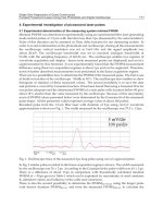
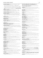
). In order to facilitate the design of multistream channel-based
diffusional mixers, the dependence of the optimum flow rate ratio, ψ
o
, on
the channel aspect ratio for various multistream or multilayer microchannel
mixers is shown in Figure 7.6. As the number of streams is increased, the
sensitivity of ψ
o
to aspect ratio is reduced and its value moves toward unity.
Starting at modest channel aspect ratios, ψ
o
approaches an almost fixed
value. For a 3-layer mixer, which has appeared frequently in the literature,
the optimum value of ψ
o
for channels with aspect ratios 3 and above is
approximately 2.2.
Also as a design aid, tabulated values of the individual stream flow rates,
FIGURE 7.6
Flow rate ratios for optimum performance of some multistream layer microchannel mixers as
function of channel aspect ratio. For an even number of streams or layers ψ
o
= 1.
ψ
n
A
B
j
j
even
i
i
odd
Q
Q
Q
Q
==
∑
∑
2
1.5
1
10
–2
10
–1
10
0
10
1
AR
Ψo
Ψ
1
3-layer
Ψ
5
5-layer
Ψ
7
7-layer
Ψ
9
9-layer
DK532X_book.fm Page 199 Tuesday, November 14, 2006 10:41 AM
as percentages of the total produced mixture flow rate, are given in Table
7.1 for 3-, 4-, and 5-layer channel mixers and for various channel aspect
see White
© 2007 by Taylor & Francis Group, LLC
Micromixers 201
(–∆p) and total mixture flow rate, Q, for the flow in the mixing channel. This
relationship can be simply expressed as:
, (7.7)
where g(AR) is a function of the aspect ratio alone.
In order to cast the analysis in a more general context, it is useful to identify
the relevant scales for all the variables. These are given in Table 7.2.
In the pressure scale, ρ is the density of the fluid(s). The length scale can
be viewed as the side of a cube whose volume is the desired mixture volume
while the time scale represents the order of magnitude of the diffusion time
necessary to mix statically in a cubic chamber with the prescribed volume.
For example, if the volume of an aqueous mixture is 10 nL and the binary
mass diffusion coefficient of the compounds is on the order of 10
–10
m
2
/s,
the length scale would be 215 µm and the time scale 464 s. The diffusive
time scale is actually one quarter of this. The scales for the volumetric flow
rate and pressure would be 21.5 pL and 0.02 Pa, respectively.
Applying this scaling to Equation 7.4, Equation 7.5, and Equation 7.7 and
eliminating the mixing length, L, from the last one we obtain:
(7.8)
(7.9)
(7.10)
TABLE 7.2
Definition of Scales
Quantity Scale
Length
Time
Volumetric Flow Rate
Pressure
Q
pw
L
gAR
M
=
−
()
∆
4
12 µ
()
t
w
Q
M
=+φ
2
2
4
1
L
Q
AR
=
1
4
2
φ
QSc
pw
AR g AR
2
4
2
3
=
−
()
∆
φ
()
V
3
VD
2
3
12
DV
12
3
ρν()V
3
2
DK532X_book.fm Page 201 Tuesday, November 14, 2006 10:41 AM
© 2007 by Taylor & Francis Group, LLC
202 Bio-MEMS: Technologies and Applications
The optimization condition that satisfies both approaches (1 and 2) above is:
(7.11)
In physical terms, this states that the optimum mixer design and operating
point is that for which the diffusion time is equal to the production time.
This applies for both possible usages where either the mixture is delivered
to an interconnected module (e.g., incubator, thermocycler, etc.) or that for
which the mixing channel itself also accommodates the next process (e.g.,
incubation, thermocycling, etc.). The latter usage, when applicable, substan-
tially reduces the volume of the microfluidic chip, which is highly desirable.
The volume for the optimum mixing channel is identical with the volume
of mixture desired. If the mixer is not operated at the optimum volumetric
flow ratio and stream volumetric flow rate proportions, the factor φ will be
other than the ideal one (1/(n-1)) and can be estimated from the chosen values
of these operational parameters. Based on the above optimum condition
(Equation 7.11) and Equation 7.8, Equation 7.9, and Equation 7.10, one can
calculate all geometric (w
o
, L
o
) and operational (Q
o
, t
Mo
or [–∆p
o
]) parameters
for the multilayer, batch production, microchannel diffusion mixer for an
aspect ratio of choice.
Summarizing at this point, the reader is reminded that there are optimum
choices to be made on two levels:
1. in terms of the optimum volumetric flow rate ratio(s), and then
2. in terms of the geometry and the other operational parameters.
As an example, results are presented as a design guide here for the popular
3-layer mixer (Ψ-junction or cross-junction), including off-optimum opera-
tion in terms of volumetric flow rate ratio(s) in the range of 0.1<Ψ<10. The
so that the effect of the aspect ratio is scaled out for AR ≥ 0.5, as evidenced
by the almost common trend for all aspect ratios for which results are shown.
Results for AR = 0.1 are also included in each figure to illustrate that this
scaling does not hold as one moves to lower aspect ratios. Subject to this
constraint, the effect of the aspect ratio is carried by the factor, f
AR
, which
can be looked up from Figure 7.11. Then, for a chosen channel aspect ratio,
Figure 7.7 can be used to determine the optimum (minimum) mixture pro-
duction time in case of approach (1) or the optimum (minimum) mixer
pressure loss in case of approach (1). Having done that, one can use the
remaining figures to determine the corresponding length of the mixing chan-
nel, L
o
, from Figure 7.8, the appropriate mixture flow rate, Q
o
, from Figure
7.9, and the appropriate mixing channel width, w
o
, from Figure 7.10. The
Q
w
=
4
22
φ
DK532X_book.fm Page 202 Tuesday, November 14, 2006 10:41 AM
optimum mixer parameters can be read from the series of Figures 7.7, 7.8,
7.9, and 7.10, with the aid of Figures 7.11 and 7.6. The former have been built
© 2007 by Taylor & Francis Group, LLC