Recent Advances in Mechatronics - Ryszard Jabonski et al (Eds) Episode 1 Part 9 doc
Bạn đang xem bản rút gọn của tài liệu. Xem và tải ngay bản đầy đủ của tài liệu tại đây (2.71 MB, 40 trang )
2. Microcutting techniques
In general, the microcutting techniques are similar to the typical cutting
operations – Table. 1. Only a few of them are new technologies. They are
fly-cutting, microgrooving and machining on atomic force microscopes
(AFM machining) [2, 3]. The last technique is also denominated as nano-
machining. The main optional realizations of kinetics are placed in the ta-
ble in brackets. In some cases the rectilinear or X-Y motions are also used
as the feed or infeed.
Table 1. Basic kinetics of microcutting techniques
Technique TURNING MILLING FLY-CUTTING DRILLING
Workpart
Tool
Technique REAMING TAPPING GROOVING
AFM MACHI-
NING
Workpart
Tool
Rotation Circulation Rectilinear motion X-Y motion
The tools for the microcutting have different size of dimensions. The ge-
ometry of the tool cutting part and the motions determined a form of the
machined surface. By combining of more motions, the shapes of almost
unlimited complexity can be produced. Well known advantage of micro-
cutting technology is the possibility to machine 3D microstructures charac-
terized by high aspect ratio. During the microcutting processes, a cutting
force is highly concentrated on the fragile tool or on the workpiece. The
relatively large elastic deformations of the miniaturized cutting tool and of
the whole machining system could be generated. Therefore, the machining
forces influence machining accuracy and limit machinable size of surfaces.
Moreover, a very careful process execution is necessary to protect the cut-
ting part of the tool against catastrophic destruction. Two main paths for
design and fabrication of the tools for microcutting are possible. The first
is downscaling of conventional tool forms and manufacturing processes.
The next utilizes newly developed technologies.
304 L. Kudła
3. Cutting tools technology
The microtools (turning cutters, drills, mills, reamers, tapping tools, hob-
bing cutters, tips etc.) are manufactured of high speed steels (HSS, HSS-E)
like Cr4W6Mo5V2 or Cr4W6Mo5Co5V2, of sintered micrograin tungsten
carbides (HM) like K10 (~WC95%Co5%) or K20/K30. Predominant tool
materials are sintered tungsten carbides and monocrystalline diamond, but
all the time persist the researches of new materials and coatings. The tools
for microcutting have various design and variety of machining methods are
necessary for their fabrication. The basics are fine abrasive techniques like
grinding, lapping and polishing. In some fabrication processes micro-
electrical-discharge machining (µEDM), laser beam machining (LBM) or
focused ion beam machining (FIBM) have been investigated [4, 5]. Down-
scaling of conventional tools is not unlimited. Therefore, the microtools
have often simplified shapes and geometry differences of smallest drills,
end-mills or reamers become slighter [6]. On the other hand a progress in
manufacturing technology enables also very fine geometry executions. An
example may be the modifications of cutting part in microdrills – Fig. 1.
d=0.24
a)
d=0.20
b)
c)
d=0.40
Fig. 1. Modifications of microdrills geometry: a) twist drill with undercut chisel
edge, b) twist drill with shell-like cavity on rake surface, c) D-shape drill with
groove parallel to major cutting edge [5]
For the cutting with a smallest thickness of cut, the radius of the tool edge
and the waviness of the cutting wedge should be reduced to the values
ranging of few microns or even considerably below. A maximal waviness
W
max
of the cutting edge is expressed by the equation
β
β
αγαγ
cos2
sin
1
22
max mmmm
RRRRW ++=
(1)
where R
m
γ
and R
m
α
represent the maximal roughness on rake and clearance
surfaces and
β
is tool wedge angle. Self-evident conclusion is that the rake
and clearance surfaces should be extremely smooth.
305Design and fabrication of tools for microcutting processes
4. Non-conventional microcutting tools
The miniaturization of tools for microcutting creates an opportunity for the
application of a very special design and fabrication processes. An example
could be the fabrication of a particular micromilling (or micro-filing) tool
[7]. The tool was made of Al disk with electroless Ni layer – Fig. 2. On the
running track of the disk the microstructures have been shaped, using fly-
cutting technique and diamond cutter. The microstructures were linear or
prismatic with height of 25 µm and spacing of 177 µm. They have follow-
ing geometry parameters: rake angle
γ
=−45
o
(negative), clearance angle
α
=10
o
, tilt angle
λ
=0
o
; 30
o
; 45
o
. After shaping, the microstructures were
coated with a 1 µm diamond-like-carbon (DLC) layer. Another and very
original solution for manufacturing of a thin milling cutter has been pro-
posed in the work [8]. The whole disk of the cutter was produced from a
gaseous phase by a chemical vapor deposition (CVD) of the diamond-like-
carbon (DLC) layer, next separated from the template former and fixed by
gluing with the shank – Fig. 3. The tool had 6 teeth with the clearance an-
gle of
α
=13
o
and the rake angle of
γ
=8
o
. The machining tests showed a
very good wear resistance of such a micromill.
1
1
3
2
2
3
50
1
3
2
2
30 µm
Fig. 2. Special disk tool for micromilling of
flat surfaces: 1) Al-disk , 2) Ni-layer, 3) run-
ning track [7]
Fig. 3. Disk mill made of DLC
layer by CVD method: 1) DLC
disc, 2) steel shank, 3) glue [8]
Many tools for the microcutting are produced from the monocrystalline
diamond. The geometry of the cutting part is formed by using of precise
abrasive techniques. It is technology of relatively low effectiveness. An
alternative may be the application of a single grain cutting tools, utilizing
natural geometry of the diamond crystal habits. The diamond grains have
very sharp corners and edges. Moreover, the grain tips have different val-
ues of the corner angle and may be individually chosen for a prospective
application. The tool preparation procedure begins with a grain selection.
306 L. Kudła
The grain having a shape of regular octahedral or cubic crystal (or its
piece) is separated from the other grains and placed in a special instrument
with grip. Next the grain is located in the holder, positioned and installed
in the tool case – Fig. 4. The diamond tools with natural geometry grains
have been successfully tested in microgrooving.
1
2
1
2
3
4
5
5
Fig. 4. Diamond turning tool with cutting edge having natural geometry of the
crystal – grain fixed in holder and design of tool set (1 - diamond crystal,
2 - holder, 3 - adjustable arm, 4 - tool case, 5 - screws)
Presented selected problems and examples shown only general trends in
technology of the tools for the realization of microcutting processes. The
continuous progress in manufacturing techniques opened a challenge as for
development of new tools as for new applications of microcutting.
References
[1] Masuzawa T., CIRP Annals, Vol.49/2/2000, 473.
[2] Kawai T., Ebihara K., Takeuchi Y., Proceedings of the 5
th
euspen* Int.
Conf., 2005, Montpellier, France, Vol.2: 607.
[3] Ashida K., Morita N., Yoshida Y., Proceedings of the 1
st
euspen* Int.
Conf., 1999, Bremen, Germany, 376.
[4] Picard Y. N. et all, Precision Engineering, Vol. 27(2003), 59.
[5] Kudł a L., Proceedings of the 6
th
euspen* Int. Conf., 2006, Ba-
den/Vienna, Austria, Vol. II: 160.
[6] Bissacco G., Surface Generation and Optimization in Micromilling. Ph.
D. Thesis, 2004, Technical University of Denmark.
[7] Brinksmeier E. et all, Proceedings of the 4
th
euspen* Int. Conf., 2004,
Glasgow, Scotland, 199.
[8] Wulfsberg J. P., Brudek G., Lehman J., Proceedings of the 4
th
euspen*
Int. Conf., 2004, Glasgow, Scotland, 131.
* European Society for Precision Engineering and Nanotechnology
307Design and fabrication of tools for microcutting processes
Ultra capacitors – new source of power.
Mirosław Miecielica (a), Marcin Demianiuk (b)
(a) Politechnika Warszawska, IIPiB
ul św. Andrzeja Boboli 8, 02-525 Warszawa, Poland
(b) OEM Automatic Sp z o.o.,
ul Postępu 2, 02-676 Warszawa, Poland
Abstract
Ultra capacitors & Super capacitors are emerging technology that
promises to play an important role in meeting the demands of electronic
devices and systems. Some people view it as the next-generation battery.
Others view it as an independent energy source capable of powering
everything from power tools to power trains. In this article we want
present internal structure those components, advantages compared with
batteries and conventional capacitors and the most interesting applications
ultra capacitors in industry applications.
1. Introduction
Ultra Capacitors & Super Capacitors are emerging technology that
promises to play an important role in meeting the demands of electronic
devices and systems. Some people view it as the next-generation battery.
Others view it as an independent energy source capable of powering
everything from power tools to power trains. This kind of capacitors
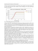
allowed to collect from few Farads to 2700 Farads in small volume
(Fig.1.). Capacity 2700 F means that we can take 1A during 45 minutes,
and voltage will fall down only 1 V. First association - this components
work like a battery. However there are few meaningful differences. For
example, we can charge these components during few seconds like
standard capacitors.
Ultra capacitors offer a number of key advantages compared with
batteries and conventional capacitors. Ultra
capacitors deliver 100 times
the energy of conventional capacitors and 10 times the power of traditional
batteries. The duty cycles are up to one million recharge cycles, even in
extreme environments. This technology reduces maintenance costs and
adds value to other power sources. This is a non-toxic, environmental
friendly solution and alternative to batteries.
Fig. 1 Ultra capacitors
family from Maxwell
[1].
2. Super capacitors technology.
In terms of energy density and access time to the stored energy,
double-layer capacitors are placed between large aluminum electrolytic
capacitors and smaller rechargeable batteries. The diagram (Fig.2) shows
the domain occupied by double-layer capacitors in the power and energy
densities space.
Figure 2. Ragone diagram, comparison of different energy storage and conversion
devices [2]
Super capacitors consist of two activated carbon electrodes, which
are immersed into an electrolyte (Fig.3). The two electrodes are separated
by a membrane which allows the mobility of the charged ions but forbids
309Ultra capacitors – new source of power
the electronic contact. The organic electrolyte supplies and conducts the
ions from an electrode to the other if an electrical charge is applied to the
electrodes. In the charged state, anions and cations are located close to the
electrodes so that they balance the excess charge in the activated carbon.
Thus across the boundary between carbon and electrolyte two charged
layers of opposed polarity are formed.
Figure 3. Electrochemical
double - layer capacitor
[2].
3. Super capacitors parameters
.
The table present technical parameters one of the most popular
model ultra capacitor – MC 2600 (2600F, 2,7V) from Maxwell. We can
find the most important parameters like: capacity, voltage, short circuit
current or internal resistance (Fig.4)
Figure 4. Technical specifications.
310 M. Miecielica, M. Demianiuk
4. Applications.
Ultra capacitors are making a difference or better performance in a
lot of areas, like automotive, industrial, traction and consumer electronic.
Applications for ultra capacitors including technologies that require:
- burst power that can be charged in seconds and then discharged
over a few minutes,
- short-term support for un-interruptible power systems,
- load-levelling for power-poor energy source such as a solar array,
- low-current, long duration power supply.
Transportation engineering
One of the main application of ultra capacitors are transportation
area. The endless cycles of acceleration and braking of vehicles, buses,
trains, cars and metro systems are ideal for this kind of technology. In
those applications ultra capacitors are used for capturing regenerative
breaking energy and reusable that energy to acceleration or supply of
supplemental electrical systems. This kind of systems can be install on-
vehicle or stationary designs (Fig 5a,5b).
Figure 5. Transportation systems
:
a) stationary, b)on-vehicle
In the automotive industry, due to the increasing power demand in
future vehicles for comfort improvement, as well as ongoing public and
governmental pressures for more environmentally friendly and fuel
efficient means of transportation, automotive manufacturers are
developing new vehicle subsystems and full hybrid systems. Super
capacitors are ideal solution to supply additional energy for electric power
steering, electromagnetic valve control, electromechanical braking, electric
door opening or hybrid drive systems. The storage of braking energy can
also be usefully applied for vehicles with internal combustion engines,
especially for the improved alternators used as braking generators.
Figure 4. Technical specifications.
311Ultra capacitors – new source of power
Industrial engineering
Ultra capacitor based energy storage and peak power solutions are
key for countless industrial applications, where they store, bridge, deliver,
ensure and smooth power and energy needs. They reliably bridge power in
uninterruptible back up power and telecom network systems, assure
around-the-clock power availability for wind turbine pitch systems, deliver
peak power for drive systems and actuators, ensure peak shaving and
graceful power-down of robotic systems, augment the primary energy
source for portable devices such as power tools, smooth energy throughput
from renewable energy storage sources like solar applications, and
efficiently enable high power pulse forming in power generators. When
appropriately applied, ultra capacitors represent an outstanding design
option for advanced power systems design. Ultra capacitors are cost-
effective, perform well, are very reliable and are first choice in terms of
energy storage technologies in many electrical and electronic systems in
the industrial domain.
Uninterruptible power supply (UPS )
Mission critical systems require high reliability and high
availability bridge power backup for seconds to minutes. Ultra capacitors
can provide high reliability, minimal to no maintenance, and highly
available power backup to enable orderly shutdown or bridge to an
alternative power source such as a generator, micro-turbine or fuel cell.
Whether you are looking at portable wireless devices, low-earth orbiting
communication satellites, cell towers or distributed, off-the-grid, high-
quality electric power for commercial and residential building
applications; premium power sources is key as it offers important benefits
to a companies bottom-line.
5. Summary
In conclusion, ultra capacitors play a large part in revolutionizing
transportation, automotive, UPS and also another domain industry. In this
kid of industry which increasingly requires power technologies that
respond to changing consumer demands for environmentally sensitive,
high-performance and low-cost super capacitors are the best solution.
References
[1] Maxwell Technologies, Inc. – www.maxwell.com
[2] A.Schneuwly, G. Sartorelli, J. Auer, B. Maher: Maxwell Technologies,
Inc. - Ultracapacitor Applications in the Power Electronic World 2006.
312 M. Miecielica, M. Demianiuk
Implementation of RoHS Technology in
Electronic Industry
R.Kisiel (a), K.Bukat (b), Z. Drozd (c), M.Szwech (c), P. Syryczyk (d) and
A. Girulska (e)
(a) Warsaw University of Technology, Institute of Microelectronics and
Optoelectronics, ul. Koszykowa 75, 00-662 Warszawa/Poland,
(b) Tele and Radio Institute, Warszawa/Poland
(c) Warsaw University of Technology, Institute of Precision and Biomedi-
cal Engineering, Warszawa/Poland
(d) Semicon Sp. Z o.o., Warszawa/Poland
(e) ELDOS, Wroclaw/Poland
Abstract
The goal of RoHS directive is to restrict the use of lead, cadmium, mer-
cury, hexavalent chromium and two halide-containing flame retardants
(PBB and PBDE). Engineers involved in design and manufacturing proc-
ess are obliged to implement only RoHS compatible components and as-
sembly process. There are two aims of the work. First, analyze of assembly
process with applying halogen free laminate and RoHS compatible com-
ponents in multizone reflow oven. On the base of performed experiments
the oven parameters which give the proper SMT joints were selected. Sec-
ond, the test samples for reliability investigation were done. The influence
of RoHS compatible solders, component terminal finishes as well as PCB
pads finishes on reliability of SMT joint were investigated and analyzed.
1. Introduction
On 2003, 13 February, European Commission had developed and imposed
new regulations: WEEE(2002/96/EC and RoHS(2002/95/EC) to the elec-
tronics industry for the environmental protection. The main reasons for
implementing new regulations were to reduce the excess hazardous mate-
rials which enter the landfill areas and reduce the influence of electronics
waste to the environment as well as to increase the materials recycling ra-
tio. The Waste of Electrical and Electronic Equipment (WEEE) directive
requires manufacturers to reduce the disposal waste of electrical and elec-
tronic products by reuse, recycling and other forms of recovery. The manu-
factures had to be responsible to recycling of electronic waste from August
13, 2005. The Restriction of the Use of Certain Hazardous Substances in
Electrical and Electronic Equipment (RoHS) directive restricts the use of
six substances specifically within all electrical and electronic equipment
traded in the EU member states. These substances are listed in Table 1.
According to the RoHS directive, companies that are not in compliance
will be unable to trade their products in member states of EU. Recognoz-
ing this global economy and the impact on the environment, other coun-
tries ought to implement EU directives too.
Tab.1 Restricted substances under the RoHS directive [1]
Substances Symbol Limits [ppm]
Lead
Mercury
Cadmium
Hexavalent Chromium
Polybrominated Biphenyls
Polybrominated Diphenyl Ethers
Pb
Hg
Cd
Cr (VI)
PBBs
PBDEs
1000
1000
100
1000
1000
1000
The implementation of lead-free technology to production status is still
unsolved problem [2]. The assembly industry is still looking for answer
which soldering materials, component termination metallurgies and printed
circuit board finishes are optimal. The use of Pb-free materials and tech-
nology has prompted new reliability problems, as the result of different
alloy metallurgies and higher assembly process temperatures relative to
SnPb technology. The selection of RoHS compliant alternatives should be
based on compatibility between materials used as component terminations,
PCB pads finishes and flux-solder systems.
Investigations of Pb-free technology for small producers of electronic
equipment (SME’s) were made in Warsaw University of Technology
(WUT) in frame of EU GreenRoSE Project. The results of performed ex-
periments are presented in this paper.
2. Design and assembly with RoHS
Engineers and designers have to take extra precautions when they are in-
volved either in manufacturing components or final systems. They are
oblidged to implement only RoHS compatible components and assembly
technology. RoHS no compliant materials and parts should be replaced
314 R. Kisiel, K. Bukat, Z. Drozd, M. Szwech, P. Syryczyk, A. Girulska
with RoHS compliant alternatives that are selected based on availability,
manufacturability, reliability, and cost consideration. System designers
need to maintain proper documentation for four years after the product has
been released to market to prove RoHS compliance all the way down to
the subcomponent level.
2.1 RoHS compliant components and material selections
The main considerations for Pb-free component selection include terminal
finish, moisture and thermal sensitivity and material and process compati-
bility. At present, pure Sn is the most widely adopted finish materials for
leadframe, followed by Ni-Pd-Au plating. For array components SnAgCu
solder ball metallurgy were widely adopted. For connectors, SnCu and
SnAgCu finishes are employed as replacement of SnPb contact finishes.
Considerations for Pb-free board design include PCB pad finish and lami-
nate material selection. The primary Pb-free alternatives to SnPb HASL
are immersion Sn, immersion Ag, electroless Ni/immersion Au, SnCu
HAL or organic solderability preservative (OSP). PCB finish selection
must be based upon the finish wetting characteristics with lead-free sol-
ders, shelf life, pad planarity and cost. PCB laminate material must with-
stand multiple reflows and rework at the appropriate Pb-free processing
temperature without thermo-mechanical damage. The laminate should be
free from polybrominated biphenols (PBB) and polybrominated diphenyl
ethers (PBDE). These halide-containing flame retardants are prohibited by
RoHS legislation. The research institutes from many countries recom-
mended Sn-Ag-Cu eutectic as the most promising Pb-free solder. Sn(3.0-
3.9)Ag(0.5-0.7)Cu appears to be the leading choice adopted by industry
both for reflow and wave soldering. Sn0.7Cu or Sn0.7CuNi is the low cost
alternatives for wave soldering recommended by some researches.
2.2 RoHS compliant soldering process
During Pb-free soldering process the components are exposed to higher
temperatures compared to SnPb reflow. Thermal sensitivity of components
and PCBs creates the need for precise control of reflow temperature pro-
file. Soldering process must be done in multizone convection reflow oven
with temperature range 300-350°C in reflow zones. Such reflow zones are
capable of heating the boards and components to the temperature range
(245-255°C) required for lead-free soldering of most products. Finding the
proper multizone reflow oven set up to perform proper soldering process is
the big challenge for small companies.
315Implementation of RoHS technology in electronic industry
3. RoHS compliant assembly of test boards
The halogen free test boards with immersion Sn and SnCu HAL as well as
0805 and 1206 components with Sn terminal finish were used for investi-
gations. The SAC305 Pb-free solder paste and Sn37Pb solder paste (as a
reference) were used for reflow soldering. The reflow soldering was done
using multizone convection oven ERSA HOTFLOW 2/14 (7 top and 7
down heating zones and 2 top +2 down cooling zones). For selecting the
optimum reflow temperature profile the Taguchi methodology was used
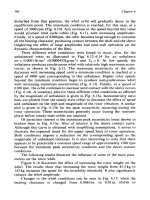
[4]. During performed series of experiments the soldering temperatures
were change in the range 235°C÷281°C and soldering time from 38 to 92s.
The SMT joint resistance and shear force of components were measured
after each test run. The methodology for SMT resistance and shear force
measurements were described in [5].The results of experiments were
shown in Fig.1. On the base of performed experiments the proper reflow
oven set up for 0805 and 1206 components was establish (T
max
=255°C,
t=47 s) and series of test boards for reliability tests were manufactured.
0
10
20
30
40
50
60
70
80
90
100
230 240 250 260 270 280 290
Soldering temperature [C]
Shear force [N]
O805
12O6
0
0,2
0,4
0,6
0,8
1
1,2
1,4
1,6
230 240 250 260 270 280 290
Soldering temperature [C]
Joint resistance
[mOhm]
O805
12O6
Fig.1 Influence of soldering tempetarure on shear force (left) and SMT joint resis-
tance (right)
4. Reliability testing of SMT joints
For reliability testing the thermal cycling and mechanical fatigue tests
were applied. During performed reliability tests the solder joint resistance
was measured after established time intervals. The resistance changes of
soldered jumpers more than 20 m� from initial value or visible cracks were
registered as failures. Thermal cycling test was performed in dual zone test
chamber (-40°C and +125°C). The comparison of the Weilbull plots for
solder joints created by SAC and SnPb alloys on test samples with Sn and
SnCu HAL finishes are shown in Fig.2. There is significant difference in
reliability of SAC and SnPb solder joints with Sn finish. The SAC alloy is
316 R. Kisiel, K. Bukat, Z. Drozd, M. Szwech, P. Syryczyk, A. Girulska
SnPB
/HAL
SAC/HAL
SAC/Sn
SnPb/Sn
SAC/Sn
SAC/HAL
SnPb/Sn
SnPb /HAL
worse. For SnCu HAL finishes the SAC and SnPb alloys had comparable
reliability.
Mechanical cycling test was realized on the laboratory stand developed in
WUT [4]. The comparison of the Weilbull plots for solder joints created by
SAC and SnPb alloys on test samples with Sn and SnCu HAL finishes are
shown in Fig.4. The SAC joints had slightly lower reliability than SnPb
joints with Sn finish.
Fig.2 Weibull plots for solder joints created by SAC and SnPb alloys: after
thermal cycling test (left) and mechanical cycling test (right)
5. Conclusions
In the paper there were presented the problems of implementation the
RoHS directive in SMEs. The Pb-free reflow soldering process was ap-
plied for assembly halogens free PCB with RoHS compliant components.
The test samples were reliability tested in thermal cycling and mechanical
fatigue tests. The obtained results showed that the component size as well
as PCB pad finishes had the influence on solder joint reliability. It was
found that in some applications the reliability of SnPb solder joints are bet-
ter than SAC solder joints.
References
[1] Eveloy V., Ganesan S., Fukuda Y., Wu J., Pecht M.G. IEEE Trans. on Com-
ponents and Packaging Technologies, vol. 28, no 4, 2005, p.884-893
[2] Drozd Z., Szwech M. Proc of ESTC 2006, Dresden, Germany, p. 1187-1193
[3] Kisiel R., Syryczyk P. Proc. of 4th EMPS, 22-24 May 2006, Terme Catez,
Slovenia, p.295-299
[4] Kisiel R., Gasior W., Moser Z., Pstrus J., Bukat K., Sitek J.: Journal of Phase
Equilibria and Diffusion, vol.25, No 2, 2004, p.122-124
317Implementation of RoHS technology in electronic industry
Simulation of Unilateral Constraint in MBS
software SimMechanics
R.Grepl
Institute of Thermomechanics, Academy of Sciences of the CR, branch
Brno, Czech Republic, email:
Abstract
This paper deals with implementation of simple unilateral constraint model
in SimMechanics environment. The point – line segment contact is mod-
elled using linear viscous – elastic model, the tangential component is con-
sidered with Coulomb friction. The block has been successfully tested on
the case of circuit breaker problem.
1. Introduction
Unilateral constraints are relatively difficult to be modelled, but in exist in
reality and are important in many industrial applications, e.g. cam-valve
models, circuit breakers and others.
SimMechanics has powerful capabilities for mechatronic: it allows to
simulate mechanical system (MBS) together with other domain models
(electrical, control) very easily. However, it is lacking for unilateral con-
straint modelling for understandable reasons [1]. Many researches are in-
terested in similar problem for different currently used MBS software [6].
This paper briefly describes the work related to:
• design of simulation blocks for simple unilateral contacts in Sim-
Mechanics
• with as fast as possible behaviour.
Particularly, in this paper we demonstrate the point – line segment contact
element.
There are basically two classes of methods dealing with the unilateral con-
straints: the Newton impulses and Hertz continuous approach. We used the
second one in our implementation, the linear viscous-elastic model is:
= =
e v
N N N k b
δ δ
+ +
(1)
Contrary to Newton method, the continuous method provides the forces
during the impact, which is very important for e.g. dimensioning of the
parts.
The contact modelling implementation
Fig. 1 shows considered
situation when the point E
penetrates into flexible sur-
face of edge (line segment)
AB. The solution can be
summarized in following
steps: 1) obtain coordinates
of points A, B and E, com-
pute relevant vectors, 2) test
if point E is in contact; 3) if
so, compute depth of contact
δ
and relative speed in
normal direction
δ
and
next; 4) compute normal
force
=
e v
N N N
+
and the
moment compensation; 5)
and optionally compute tangential friction force T and finally; 6) apply
resulting force to “point” body (point E) and apply force and compensatory
moment to “line” body - particularly to point A.
The global coordinates of points A, B and E can be read easily using Body
Sensor block connected to relevant CS port of Body as shown in Fig. 2.
The testing of possible contact (relative position of point and line) can be
accomplished by the vector product. Obviously, the resulting vector of
vector product is oriented in z direction; therefore just following scalar
formulation can be used:
=
= = ( , );
z x y x y s
w u v
w u v v u f u v
×
−
(2)
The tests can be written this way:
1 2 3 2
= ( , ), = ( , ), = ( , )
s s s
f b e f u e f u e
λ λ λ
(3)
The complete test criterion is
Fig. 1. Schema of point - line segment contact
task
319Simulation of unilateral constraint in MBS soware SimMechanics
1 2 3
= 0 0 0
λ λ λ λ
≤ ∧ ≤ ∧ ≥
(4)
If
=1
λ
, then point E is in contact with edge AB and we compute contact
force, otherwise contact force is zero.
The deformation (depth) in contact
δ
can be computed as the distance of
point to line using
= ( ) ( )
x E A y E A
u x x u y y
δ
− + −
(5)
Fig. 2. Simulation schema of point – line segment contact block in Sim-
Mechanics
Further, we can obtain the elastic component of normal force N
e
according
to eq. 1. Viscous component of normal force requires the relative velocity
between point E and point D, which is the projection of contact point on
line AB. We assume, that AB is part of the rigid body, than the principles
of absolute and relative velocities of points on body are valid and we can
formulate:
| |
= , = , =
| |
=
1
= ( )
| |
BA B A DA BA D A DA
E D
x x y y
e
v v v v v v v v
b
v v
u u
u
δ
δ δ δ
− +
−
+
(6)
320 R. Grepl
After that, the viscous component of force and complete vector of normal
force are:
=
=
| |
v
e v
N b
N N
N u
u
δ
−
+
(7)
If required, we can also model the Coulomb (dry) friction using well
known formulation:
=
T Nf
(1)
where f is coefficient of Coulomb friction. Similarly can be modelled vis-
cous friction or other more advanced (and complicated) models. As
a minimal practical improvement, it is useful to consider the dependence
of f on the velocity (kinematic and static friction coefficient – sliding and
sticking mode).
Tangential friction force can be written in vector form thus way:
( )
= ( )
| |
e v
N N f
T sgn v b
b
+
−
(8)
Finaly, we add both vectors and obtain total contact force in vector form
=
F N T
+
(9)
Computed resulting force F acts on "point" body in E and in opposite di-
rection on "line" body in point D. In SimMechanics, one can apply any
force and/or moment to fix defined point only, while the D is floating.
Therefore, we apply the force to point A and to ensure the statically
equivalent load, we add the compensating moment
=
M e N
×
(10)
Practically in SimMechanics, the force and moment can act on body using
Body Actuator block.
The computation described above is implemented in Simulink and m-
Function block. All relevant blocks are included into masked subsystem
which provides user friendly interface. User connects the three points A, B,
E and defines parameters k, b, f. Resulting schema of block is shown in
Fig. 2. The solution with relatively slow Matlab-Function can be replaced
by S-Function in the future.
2. Conclusion
In this paper, we described the implementation of simple type of unilateral
constraint problem in MBS software SimMechanics. The continuous Hertz
321Simulation of unilateral constraint in MBS soware SimMechanics
approach has been used with linear viscous and elastic component. There
are still open questions about the parameters of contact problem which
should be carefully selected; the rather suitable explanation is in [2].
From the practical point of view, the used might be informed, that the stiff
solver has to be used for this problem, the best results has been obtained by
ode23. The developed simulation blocks have been successfully tested on
the problem of circuit breaker contact making.
In the future, the technique described here can be used for the building of
more advanced constraint block such as point – curve or even curve –
curve contact problem. The extension in spatial contact is also possible,
but surely significantly more demanding.
Acknowledgment
The published results have been acquired be support of project
AV0Z20760514 and GA�R 101/06/0063.
References
[1] Wood, G.D.: Simulating mechanical systems in Simulink with Sim-
Mechanics, The MathWorks Inc.,www, 2002
[2] Pogorelov, D.: Universal Mechanics, manual, part 2,
p.35–37, 2006
[3] Faik, Witteman: Modeling of Impact Dynamics: A Literature Survey,
2000 International ADAMS User Conference, 2000
[4] Tasora, A., Righettini, P.: Sliding contact between freeform surface in
three-dimensional space, GIMC 2002, ’Third Joint Conference of
Italian Group of Computational Mechanics and Ibero-Latin America
Association of Computational Methods in Engineering, 22-24 June 2002,
Giulianova - Italy, 2002
[5] Tasora A.: An optimized lagrangian-multiplier approach for interactive
multibody simulation in kinematic and dynamical digital prototyping, VIII
ISCSB, International Symposium on Computer Simulation in Biomechan-
ics, 4-6 July 2001, Politecnico di Milano, Italy, 2001
[6] Bottasso, C.L., Trainelli, L.: Implementation of effective procedures
for unilateral contact modeling in multibody dynamics, Mechanics
Research Communications, Vol. 28, pp.233–246, 2001
[7] Wasfy, T. M., Ahmen, K. N.: Computational procedure for simulating
the contact/impact response in flexible multibody systems, Computer
methods in applied mechanics and engineering, Vol. 147, pp. 153–166,
2006
322 R. Grepl
Fast prototyping approach in design of new type
high speed injection moulding machine*
K. Janiszowski, P. Wnuk
Institute of Automation and Robotics,
Warsaw University of Technology, A. Boboli 8, Warsaw 02-525, Poland
Abstract
In paper is outlined an application of PExSim - a package for simulation
and research dynamic control systems, for investigation a solution of very
fast, hydrostatic positioning of a form in high speed moulding machine
(HSIM). This construction, based on new locking mechanism, shall attain
a 1s dry cycle time for form mass of 3000 kg and 0.5m distance of posi-
tioning. Complex mechanism of highly nonlinear transmission ratio, is
moved by a set of hydraulic plunger cylinders, that are supplied by a con-
stant stroke, small inertia pump, driven by very dynamic electric motor.
Different limitations of final construction have induced many constraints at
control. The design of locking mechanism and final control program was
developed by many experiments performed by SimulationX and PExSim.
Some expected transients of the mould control will be presented.
1. Introduction
Introduction of new types of electric AC-servo motors has induced small
revolution in construction of different high power drive systems. In case of
HSIM machines an electric direct drive in comparison of classic solution -
hydraulic cylinder supplied by proportional, throttling valve and variable
volume pump driven by electric cage motor, has increased power effi-
ciency and deleted unwanted leakages. However pure electric drive has
shown some disadvantages in use – transmission mechanisms have shown
wear effects. HSIM machine makes usually 10000 heavy strokes, (eg.
3000 kg mass with acceleration of 2-4g) per day, hence construction has to
be very endurable. A construction with intermediate hydraulic circuit, con-
taining hydraulic accumulators, can significantly reduce the stroke effects.
Application of AC-servo (working only in time of movement) with low
inertia, constant stroke pump, without throttle valve, will remarkable in-
crease power efficiency. Position control was very important – form has to
be stopped at final position with velocity less 20 mm/s, when its maximum
within movement was appr. 2m/s. Modelling of the entire drive system and
development of proper control algorithm was quite complex problem.
2. Fast prototyping of construction
Fast prototyping approach was focused on two main aims: decrease of
costs and time of project. To avoid unnecessary expenditure of building
alternative prototypes (for choice of the best final machine), cooperating
with different AC-servo drives, valves systems etc. all main mechanical
components are modeled by simulation package SimulationX ™. This re-
sults were used for determination of extreme values of electric and me-
chanical components, that have determined power and dimensions of nec-
essary components: motors, pumps, accumulators, switching valves,
mechanism, etc. Next cooperating partners: machine builder (1 team),
drive and melting extruder suppliers (2 teams), control engineers (2 teams)
have to investigate its capabilities and deliver proper components. Each
team was working individual and parallel. Institute of Automatic Control
and Robotics of Warsaw University of Technology was involved in design
of fast control of moulding form. Results of simulated (in SimulationX™)
[2] responses of drive components, in form of parametric model were next
used for development of two control concepts: modified state space control
and adaptive open loop control for positioning of form. A last phase – de-
sign and testing of position control was implemented on PExSim platform.
3. PExSim package
Software simulation of dynamic systems is common used technique for
investigation of system behavior in different operation conditions. All
modern SCADA systems have some tools for modeling dynamic blocks,
but they are adopted to a platform used by this system and are not stan-
dard. Other approach to simulation is based on special written tools pack-
ages, that can be used to modeling or simulation with demanded accuracy,
when the models of process are known, e.g. SimulationX [2], designed for
simulation of fluidic and electro-mechanical structures with built in large
libraries of components of elaborated integration techniques. These tools
are however limited in area of control design possibilities and are quite
expensive. Other tools, like e.g. general purpose system - Matlab package
[3] with Simulink, used in academic institutions are based on assumption,
324 K. Janiszowski, P. Wnuk
that system dynamic is well known. This approach, creating all possible
effects from basic components, based on blocks with very simple nature,
yields an uncomfortable result: a simulation of more complex phenome-
non, e.g. nonlinear friction force or PID controller induces a quite complex
block diagram with 30 - 40 or more basic blocks. User effort and time,
necessary to creating, testing and verification of all used components, is
high and in effect this tools is used for simulation rather simple systems.
The package PExSim (Process Explorer
and Simulator), baased on plugin archi-
tecture can be used for emulation of
complex dynamic systems, composed of
predefined dynamic blocks or multivari-
able models (estimated with own proce-
dures), can cooperate in real time with
industrial environment and will be easy
and flexible to extension by the user
writing its own plugin objects, in C++.
PExSim contains following operators
and components, shown on Fig.1,
Signal “sources” contains deterministic
or stochastic time functions, imported
signals from real time interface or data
files. As sinks are short described out-
puts, that can be plotted, stored on file or
transferred to real time process or pro-
ject subsystems. Components named as
mathematic operators, discrete opera-
tions, crisp and fuzzy logic are used for
signal processing. General purpose dy-
namic components – linear dynamic
(transfer functions and state space repre-
sentation) together with “nonlinear dynamic” – a solver of nonlinear de-
fined equations show simulation abilities within deterministically desribed
dynamic systems. MITforD models is a class of fuzzy MIMO models of
TSK (Takagi, Sugeno, Kanga) form [1,4]. For construction of block dia-
gram for simulation the user has different options gathered in: execution
control, signal routing and nonlinear elements. Option “Ports and subsys-
tems” enables construction of sub-pathes, representing dynamic subsys-
tems of simulated structure in form of one block with defined inputs and
outputs nodes. PExSim contains sets of founded specialized libraries too,
Fig.1.PExSim options
325Fast prototyping approach in design of new type high speed injection moulding
like: controllers, electric components, pneumatic elements, water steam
dependencies. Own user procedures can be incorporated into package by
C/C++ scripts option. For current investigation properties of supervised
values can be used statistic operators and heuristic tests. Option called “pa-
rameter optimization” can be used for minimization of defined quality in-
dex, e.g. sum of squares errors of simulated structure in respect to variable
parameters of this model.
4. Modelling of HSIM machine
A drive system was divided into blocks: electric AC servo motors with
pumps, creating pressures in hydraulic cylinders, cylinders with moved
mass, mechanism for creating clumping force, controllers and displays,
Fig.2.
Fig. 2. General structure of modeled system
Existing in Fig.2 blocks, had to be either: deterministically defined, e.g.
models of motors (DC Motor 1) with controllers (DC amplifier), Fig.3,
PID controller or clumping mechanism, etc.
326 K. Janiszowski, P. Wnuk
Fig. 3. Structure of motor “subpath” called Motor1 on Fig.2.
or statistically estimated, using
MITforD package, Fig. 4.
Fig.4 Model of pumps for Fig.2 Fig. 5. Modeled and measured
mould position
A block called mechanics, in Fig.2, was expressing a strongly non-linear
transmission of force, developed in special toggle system. This mechanism
was invented for amplification a clumping force in ratio 1:300 for the lock-
ing phase of clumping movement. Its action was practically static, variable
ratio force transmission, dependent on mould-form position. It was mod-
eled in form look-up table plugin, contained in non-linear elements option.
Different algorithms for mould form movement control were tested using
PExSim package. A demand of very short time of complete mould move-
ment: to the form and withdraw, has resulted in decision – drive as fast as
possible, the whole movement time and control, with position measure-
ment, only at closing mould to the form. At open control of form, only
limitations of machine were important: maximal pressures in hydraulic
pipes, maximal current of motors, maximal velocity of pumps and maxi-
mal acceleration of drive. At final position control, the form velocity and
positioning error were important. Then two approaches were used: a modi-
fied state space control with feedback of position, velocity and decelera-
tion of form and open loop adaptive control for minimal time of form stop.
The proper instants of AC-servo time switching were determined adap-
tively within 4-6 first dry cycles of mould. This last approach was devel-
oped after investigations and experiments made in PExSim, with different
adaptively estimated parameters. Finally a simple model of mould move-
ment was derived, that had only two tuned parameters. This approach was
next tested in SimulationX too. The transients of SimulationX were a
common platform for all cooperating teams, so the corresponding results
327Fast prototyping approach in design of new type high speed injection moulding
can be easy transferred and verified by co-partners of HSIM project. A
sample of movements, for a 2000 kg form and displacement of 45 cm,
plotted in SimulationX are presented on Fig. 6.
Fig.6 Transients of adaptive control movement of form in HSIM machine
6. Conclusions
A fast prototyping is very efficient and time saving approach in design of
complex, new constructions. It should be mentioned, that within this pro-
ject were tested three different configuration of hydraulic systems (with
different number of motors, pumps and auxiliary valves), were investi-
gated 2 different construction of clumping force mechanisms, 3 algorithms
for injection and 3 algorithms for clumping form movements and 4 differ-
ent versions of hydraulic supply, oil accumulator and cooling systems. Fi-
nally developed construction seems to be very economic, in component
number, but of high quality and good parameters, has involves small en-
ergy loses and can be so fast as demanded, after getting together experi-
ence and knowledge of different cooperating teams. An elaboration of such
effect by one team – machine constructor, will take much more time and
will never resulted in so good final parameters of machine.
7. Aknowledgements
The paper was partially sponsored by grant 004/ITE/3/2005
8. References
[1] Janiszowski K. Parametric models identification, Exit 2002,
Warsaw,
328 K. Janiszowski, P. Wnuk