The MEMS Handbook Introduction & Fundamentals (2nd Ed) - M. Gad el Hak Part 12 doc
Bạn đang xem bản rút gọn của tài liệu. Xem và tải ngay bản đầy đủ của tài liệu tại đây (434.08 KB, 30 trang )
12.5 Change of Phase: Evaporation and Condensation
12.5.1 Interfacial Conditions
We now consider the case of an evaporating (condensing) thin film of a simple liquid lying on a heated
(cooled) plane surface held at constant temperature ϑ
0
which is higher (lower) than the saturation tem-
perature at the given vapor pressure. It is assumed that the speed of vapor particles is sufficiently low, so
that the vapor can be considered an incompressible fluid.
The boundary conditions appropriate for phase transformation at the film interface z ϭ h are now for-
mulated. The mass conservation equation at the interface is given by the balance between the liquid and
vapor fluxes through the interface
j ϭ
ρ
υ
(v
υ
Ϫ v
i
) и n ϭ
ρ
f
(v
f
Ϫ v
i
) и n, (12.79a)
where j is the mass flux due to evaporation;
ρ
υ
and
ρ
f
are, respectively, the densities of the vapor and the
liquid; v
υ
and v
f
are the vapor and liquid velocities at z ϭ h; and v
i
is the velocity of the interface. Equation
(12.79a) provides the relationship between the normal components of the vapor and liquid velocities at
the interface. The tangential components of both of the velocity fields are equal at the interface:
(v
f
Ϫ v
υ
) и t
m
ϭ 0, m ϭ 1, 2. (12.79b)
The boundary condition that expresses the stress balance and extends Equation (12.4b) to the case of
phase transformation reads [Delhaye, 1974; Burelbach et al., 1988]
j(v
f
Ϫ v
υ
) Ϫ (T Ϫ T
υ
) и n ϭ 2H
~
σ
(ϑ)n Ϫ ∇
s
σ
, (12.80a)
where T
υ
is the stress tensor in the vapor phase and temperature dependence of surface tension is
accounted for.
The energy balance at z ϭ h is given by [Delhaye, 1974; Burelbach et al., 1988]
j
L ϩ
υ
2
υ
,n
Ϫ
υ
2
f,n
ϩ (k
th
∇ϑ Ϫ k
th,
υ
∇
ϑ
υ
) и n ϩ 2
µ
(e
f
и n) и v
f,r
Ϫ 2
µ
υ
(e
υ
и n) и v
υ
,r
ϭ 0, (12.80b)
where L is the latent heat of vaporization per unit mass; k
th,
υ
,
µ
υ
,
ϑ
υ
are, respectively, the thermal con-
ductivity, viscosity, and the temperature of the vapor; v
υ
,r
ϭ v
υ
Ϫ v
i
, v
f,r
ϭ v
f
Ϫ v
i
are the vapor and liq-
uid velocities relative to the interface, respectively;
υ
υ
,n
ϭ v
υ
,r
и n, v
f,n
ϭ v
f,r
и n are the normal components
of the latter; and e
f
, e
υ
are the rate-of-deformation tensors in the liquid and the vapor, respectively. In
Equation (12.80b) the first term represents the contribution of the latent heat, the combination of the
second and the third terms represents the interfacial jump in the momentum flux, the combination of the
fourth and the fifth terms represents the jump in the conductive heat flux at both sides of the interface,
while the combination of the last two terms is associated with the viscous dissipation of energy at both
sides of the interface.
Since
ρ
υ
/
ρ
f
ϽϽ 1, typically of order 10
Ϫ3
, it follows from Equation (12.79a) that the magnitude of the
normal velocity of the vapor relative to the interface is much greater than that of the liquid. Hence, the
phase transformation causes large accelerations of the vapor at the interface where the back reaction,
called the vapor recoil, represents a force exerted on the interface. During evaporation (condensation) the
troughs of the deformed interface are closer to the hot (cold) plate than the crests, so they have greater
evaporation (condensation) rates j. The dynamic pressure at the vapor side of the interface is much larger
than that at the liquid side,
ρ
υ
υ
2
υ
,n
ϭ ϾϾ
ρ
f
υ
2
f,n
ϭ . (12.81)
j
2
ᎏ
ρ
f
j
2
ᎏ
ρ
υ
1
ᎏ
2
1
ᎏ
2
Physics of Thin Liquid Films 12-35
© 2006 by Taylor & Francis Group, LLC
Momentum fluxes are thus greater in the troughs than at the crests of surface waves. Vapor recoil is a
destabilizing factor for the interface dynamics for both evaporation (j Ͼ 0) and condensation (j Ͻ 0)
[Burelbach et al., 1988]. Scaled with j
2
, see Equation (12.84), the vapor recoil is only important for appli-
cations where very high mass fluxes are involved.
Vapor recoil generally exerts a reactive downward pressure on a horizontal evaporating film. Bankoff
(1961) introduced the effect of vapor recoil in the analysis of the film boiling. In this analysis the liquid
overlays the vapor layer generated by boiling and leads to the Rayleigh–Taylor instability of an evaporating
liquid–vapor interface above a hot horizontal wall. In this case the vapor recoil stabilizes the film boiling
because the reactive force is greater for the wave crests approaching the wall than for the troughs.
To obtain a closure for the system of governing equations and boundary conditions, an equation relating
the dependence of the interfacial temperature
ϑ
i
and the local pressure in the vapor phase is added
[Plesset and Prosperetti, 1976; Palmer, 1976; Sadhal and Plesset, 1979]. Its linearized form is
~
Kj ϭ ϑ
i
Ϫ ϑ
s
ϵ ∆ϑ
i
, (12.82)
where
~
K ϭ
1/2
,
ϑ
s
is the absolute saturation temperature,
ˆ
α
is the accommodation coefficient, R
υ
is the universal gas constant,
and M
w
is the molecular weight of the vapor [Palmer, 1976; Plesset and Prosperetti, 1976; Burelbach et al.,
1988]. Note that the absolute saturation temperature ϑ
s
serves now as the reference temperature instead of
ϑ
∞
in the normalization, Equation (12.49). When ∆ϑ
i
ϭ 0, the phases are in thermal equilibrium with each
other, and in order for net mass transport to take place, a vapor pressure driving force must exist, given for
ideal gases by kinetic theory [Schrage, 1953]. The latter is represented in the linear approximation by the
parameter
~
K [Burelbach et al., 1988]. Departure from ideal behavior is addressed in the parameter
~
K by
the presence of an accommodation coefficient
ˆ
α
depending on interface/molecule orientation and steric
effects which represents the probability of a vapor molecule sticking upon hitting the liquid–vapor interface.
The set of the boundary conditions Equations (12.80) can be simplified to what is known as a “one-
sided” model for evaporation or condensation [Burelbach et al., 1988] in which the dynamics of the liq-
uid are decoupled from those of the vapor. This simplification is possible because of the assumption of
smallness of density, viscosity, and thermal conductivity of the vapor with respect to the respective prop-
erties of the liquid. The vapor dynamics are ignored in the one-sided model, and only the mass conser-
vation and the effect of vapor recoil stand for the presence of the vapor phase.
The energy balance Equation (12.80b) becomes
Ϫk
th
∇ϑ и n ϭ j
L ϩ
, (12.83)
suggesting that the heat flux conducted to the interface in the liquid is converted to latent heat of evapo-
ration and the kinetic energy of vapor particles.
The stress balance at the interface Equation (12.80a) is reduced and now rewritten explicitly for the
components of the normal and tangential stresses as
Ϫ Ϫ T и n и n ϭ 2H
~
σ
(ϑ),
T и n и t ϭ ∇
s
σ
и t.
(12.84)
In Equation (12.84) the j
2
-term stands for the contribution of vapor recoil. Finally, the remaining bound-
ary conditions Equations (12.79) and (12.82) are unchanged.
j
2
ᎏ
ρ
υ
j
2
ᎏ
ρ
υ
2
1
ᎏ
2
2
π
R
υ
ᎏ
M
w
ϑ
s
3/2
ᎏ
ˆ
αρ
υ
L
12-36 MEMS: Introduction and Fundamentals
© 2006 by Taylor & Francis Group, LLC
The procedure of asymptotic expansions outlined in the beginning of this chapter is used again to
derive the pertinent evolution equation. The dimensionless mass balance Equation (12.13) is modified by
the presence of the non-dimensional evaporative mass flux, J ϭ jdL/k
th
(ϑ
0
Ϫ ϑ
s
)
EJ ϭ (ϪH
τ
Ϫ UH
ξ
Ϫ VH
η
ϩ W)(1 ϩ H
2
ξ
)
Ϫ1/2
, (12.85a)
or at leading order of approximation
H
τ
ϩ Q
ξ
(x)
ϩ Q
η
(y)
ϩ EJ ϭ 0, (12.85b)
where Q
(x)
(
ξ
,
η
,
τ
) ϭ
͵
H
0
Udς, Q
(y)
(
ξ
,
η
,
τ
) ϭ
͵
H
0
V dς are the components of the scaled volumetric flow rate
per unit width parallel to the wall. The parameter E in Equation (12.85) is an evaporation number
E ϭ ,
which represents the ratio of the viscous time scale t
v
ϭ d
2
/v to the evaporative time scale, t
e
ϭ
ρ
d
2
L/k
th
(ϑ
0
Ϫ ϑ
s
) [Burelbach et al., 1988].
The dimensionless versions of Equations (12.82) and (12.83) are:
KJ ϭ Θ at ς ϭ H,
Θ
ς
ϭ ϪJ at ς ϭ H, (12.86)
where
K ϭ
~
K .
In the lower equation in Equation (12.86) the kinetic energy term is neglected. For details refer to
Burelbach et al. (1988). Equations (12.18), (12.19), (12.53), and (12.86) pose the problem whose solution
is substituted into Equation (12.85b) to obtain the sought evolution equation. The general dimensionless
evolution Equation (12.21) will then contain an additional term EJ, which arises from the mass flux
because of evaporation and condensation now expressed via the local film thickness H.
A different approach to theoretically describe the rate of evaporative flux j in the isothermal case is
known in the literature [Sharma, 1998; Padmakar et al., 1999]. This approach is based on the extended
Kelvin equation that accounts for the local interfacial curvature and the disjoining and conjoining pressures,
both entering the resulting expression for the evaporative mass flux j. It was shown by Padmakar et al. (1999)
that their evaporation model admits the emergence of a flat adsorbed layer remaining in equilibrium with
the ambient vapor phase, and thus in this state the evaporation rate from the film vanishes. This adsorbed
layer, however, is usually several molecular spacings thick, which is beyond the resolution of continuum
theory.
12.5.2 Evaporation/Condensation Only
We first consider the case of an evaporating or condensing thin liquid layer lying on a rigid plane held at
constant temperature. Mass loss or gain is retained, while all other effects are neglected.
Solving first Equation (12.53) along with boundary conditions Equations (12.51a) and (12.86) and
eliminating the mass flux J from the latter yields the dimensionless temperature field and the evaporative
mass flux through the interface
Θ ϭ 1 Ϫ
,
J ϭ
.
(12.87)
1
ᎏ
H ϩ K
ς
ᎏ
H ϩ K
k
th
ᎏ
dL
k
th
(ϑ
0
Ϫ ϑ
s
)
ᎏᎏ
ρν
L
Physics of Thin Liquid Films 12-37
© 2006 by Taylor & Francis Group, LLC
An initially flat interface will remain flat as evaporation or condensation proceeds. If surface tension,
thermocapillary, and convective thermal effects are negligible (i.e., M ϭ S ϭ
ε
RP ϭ 0), it will give rise to
a scaled evolution equation of the form
H
τ
ϩ ϭ 0, (12.88)
where E
ෆ
ϭ
ε
Ϫ1
E, positive in the evaporative case and negative in the condensing one. K, the scaled inter-
facial thermal resistance, is equivalent to the inverse Biot number B
Ϫ1
. On the physical grounds, K 0
represents a temperature jump from the liquid surface temperature to the uniform temperature of the
saturated vapor ϑ
s
. This jump drives the mass transfer. The conductive resistance of the liquid film is pro-
portional to H, and the total thermal resistance, assuming infinite thermal conductivity of the solid, is
given by (H ϩ K)
Ϫ1
. For a specified temperature difference ϑ
0
Ϫ ϑ
s
Equation (12.88) represents a volu-
metric balance whose solution, subject to the initial condition H (
τ
ϭ 0) ϭ 1, is
H ϭ ϪK ϩ [(K ϩ 1)
2
Ϫ 2E
ෆ
τ
]
1/2
. (12.89)
In the case of evaporation E
ෆ
Ͼ 0 and when K 0, the film vanishes in a finite time
τ
e
ϭ (2K ϩ 1)/2E
ෆ
, and
the rate of disappearance of the film at
τ
ϭ
τ
e
is finite
Έ
τ
ϭ
τ
e
ϭ Ϫ
.
For K 0, the value of dH/d
τ
remains finite, because as the film thins the interface temperature ϑ
i
, nom-
inally at its saturation value ϑ
s
, increases to the wall temperature. If K ϭ 0 however, the problem becomes
singular. In this case the thermal resistance vanishes, and the mass flux will increase indefinitely if a finite
temperature difference ϑ
0
Ϫ ϑ
s
is sustained. The speed of the interface at rupture becomes infinite as well.
Burelbach et al. (1988) showed that the interfacial thermal resistance K ϭ 10 for a 10 nanometers thick
water film. Since K is inversely proportional to the initial film thickness, K Ϸ 1 for d ϭ 100 nanometers,
so that H/K Ϸ 1 at this point. However, H/K Ϸ 10
Ϫ1
at d ϭ 30 nanometers, so that the resistance to con-
duction is small compared to the interfacial transport resistance. Shortly after, van der Waals forces
become appreciable.
12.5.3 Evaporation/Condensation, Vapor Recoil, Capillarity, and
Thermocapillarity
The dimensionless vapor recoil gives an additional normal stress at the interface determined by the j
2
-term
in Equation (12.84), Π
ˆ
3
ϭ Ϫ
3
–
2
E
ෆ
2
D
Ϫ1
J
2
, where D is a unit-order scaled ratio between the vapor and
liquid densities
D ϭ
ε
Ϫ3
.
This stress can be calculated using Equation (12.87). The resulting scaled evolution equation for an evap-
orating film on an isothermal horizontal surface neglecting the thermocapillary effect and body forces is
obtained using the combination of Equations (12.21) and (12.88) with Π
1
ϭ 0, Σ
ξ
ϭ 0 [Burelbach et al.,
1988]:
H
τ
ϩ ϩ
΄
E
ෆ
2
D
Ϫ1
3
H
ξ
΅
ξ
ϩ S(H
3
H
ξξξ
)
ξ
ϭ 0. (12.90)
Since usually t
e
ϾϾ t
v
, E
ෆ
can be a small number and can be used as an expansion parameter for slow eva-
poration compared to the non-evaporating base state [Burelbach et al., 1988] appropriate to very thin
evaporating films.
1
ᎏ
3
H
ᎏ
H ϩ K
E
ෆ
ᎏ
H ϩ K
ρ
υ
ᎏ
ρ
3
ᎏ
2
E
ෆ
ᎏ
K
dH
ᎏ
d
τ
E
ෆ
ᎏ
H ϩ K
12-38 MEMS: Introduction and Fundamentals
© 2006 by Taylor & Francis Group, LLC
Taking into account van der Waals forces and thermocapillarity, the complete evolution equation for a
thin heated or cooled film on a horizontal plane surface was givenbyBurelbach et al. (1988) in the form
H
τ
ϩ ϩ
Ά΄
AH
Ϫ1
ϩ E
ෆ
2
D
Ϫ1
3
ϩ KM
ෆ
P
Ϫ1
2
΅
H
ξ
·
ξ
ϩ S(H
3
H
ξξξ
)
ξ
ϭ 0 (12.91)
with M
ෆ
ϭ
ε
M.Here the first term represents the rate of volumetric change; the second one the mass
loss/gain; the third, fourth, and fifth ones the attractive van der Waals, vapor recoil, and thermocapillary
terms, all destabilizing; while the sixth term describes the stabilizing capillary force. This was the first full
statement of the possible competition among various stabilizing and destabilizing effects on a horizontal
plate, with scaling making them present at the same order. Other effects such as gravity may be included
in Equation (12.91). Joo et al. (1991) extended the work to an evaporating (condensing) liquid film drain-
ing down a heated (cooled) inclined plate.
Oron and Bankoff (1999) studied the two-dimensional dynamics of an evaporating ultrathin film on
acoated solid surface when the potential Equation (12.31d) was used. Three different types of the evolu-
tion of avolatile film were identified. One type is related to low evaporation rates associated with rela-
tively small E
ෆ
Ͼ 0 when holes covered by a liquid microlayer emerge, and the expansion of such holes is
governed mainly by the action of the attractive molecular forces. These forces impart the squeeze effect
to the film and, as a result of this, the liquid flows away from the hole. In this stage the role of evapora-
tion is secondary. Figure 12.9 displays such an evolution of avolatile liquid film. Following the nucleation
of the hole and during the process of surface dewetting, one can identify the formation of a large ridge,
or drop, on either side of the trough. The former grows during the evolution of the film until the drops
at both ends of the periodic domain collide. A further recession of the walls of the dry spot leads to the
formation of a single large drop that flattens and ultimately disappears, according to Equation (12.89).
The stages of the film evolution shown in Figure 12.9(a) are very similar to that sketched in Figure 3 of
Elbaum and Lipson (1995). This type of evolution also resembles the results obtained by Padmakar et al.
(1998) for the isothermal film subject to hydrophobic interactions and to evaporation driven by the dif-
ference between the equilibrium vapor pressure and the pressure in the vapor phase. Such films thin uni-
formly to a critical thickness and then spontaneously to dewet the solid substrate by the formation of
growing dry spots when the solid was partially wetted. In the completely wetted case, thin liquid films evolved
to an array of islands that disappeared by evaporation to a thin equilibrium flat film. Two other regimes
corresponding to intermediate and high evaporation rates were discussed in Oron and Bankoff (1999).
An important phenomenon was found in the last stage of the evolution of an evaporating film where
the latter finally disappears by evaporation: prior to that the film equilibrates, so that its disappearance is
practically uniform in space. The film equilibration is caused by the “reservoir effect,” which is driven by
the difference in disjoining pressures and manifests itself by feeding the liquid from the large drops into
the ultrathin film that bridges between them.
Oron and Bankoff (2001) studied the dynamics of condensing thin films on a horizontal coated solid
surface. In the case of arelatively fast condensation, where the initial depression of the interface rapidly
fills up because of the enhanced mass gain there, the film equilibrates and grows uniformly in space
according to Equation (12.89). Note that E
ෆ
Ͻ 0. When condensation is relatively slow, the evolution of
the film exhibits several distinct stages. The first stage, dominated by attractive van der Waals forces, leads
to the opening of a hole covered by a microlayer, as shown in the first three snapshots of Figure 12.10(a).
This is accompanied with continuous condensation with the highest rate of mass gain attained in the
microlayer region corresponding to the smallest thickness H in Equation (12.87). However, opposite to
the evaporative case [Oron and Bankoff, 1999], where the “reservoir effect” arising from the difference
between the disjoining pressures causes feeding of the liquid from the large drops into the microlayer and
film equilibration, in the condensing case the excess liquid is driven from the microlayer into the large
drops. This effect is referred to as the “reversed reservoir effect.” The thickness of the microlayer remains
nearly constant because of local mass gain by condensation compensating for the impact of the reverse
reservoir effect. The first stage of the film evolution terminates in the situation where the size of the hole
1
ᎏ
3
H
ᎏ
H ϩ K
H
ᎏ
H ϩ K
E
ෆ
ᎏ
H ϩ K
Physics of Thin Liquid Films 12-39
© 2006 by Taylor & Francis Group, LLC
is the largest. The receding of the drops stops due to the increase of the drop curvature and buildup of
the capillary pressure that comes to balance with the squeeze effect of the attractive van der Waals forces.
From this moment the hole closes driven by condensation, as shown in Figure 12.10(a, b). Once the hole
closes, the depression fills up rapidly, the amplitude of the interfacial disturbance decreases, and the film
tends to flatten out. The film then grows uniformly in space following the solution Equation (12.89) with
negative E
ෆ
.
Oron (2000c) studied the three-dimensional evolution of an evaporating film on a coated solid surface
subject to the potential Equation (12.31d). The main stages of the evolution repeat those mentioned pre-
viously in the case of a non-volatile film in the section on isothermal films, except for the stage of disap-
pearance accompanied by the reservoir effect. Because of the reservoir effect, the minimal film thickness
decreases very slowly during the stage of film equilibration.
12.5.4 Flow on a Rotating Disc
Reisfeld et al. (1991) considered the axisymmetric flow of an incompressible viscous volatile liquid on a
horizontal, rotating disk. The liquid was assumed to evaporate because of the difference between the
12-40 MEMS: Introduction and Fundamentals
1.5
1.0
(a)
(b)
0.5
0.0
0.08
0.07
0.06
0.05
0.04
0.03
0.02
0.01
0.00
HH
FIGURE 12.9 The evolution of a slowly evaporating film: (a) the initial and intermediate stages of the film evolu-
tion, and (b) the final stage of the evolution. The curves in both graphs correspond to the interfacial shapes in con-
secutive times (not necessarily equidistant). (Reprinted with permission from Oron and Bankoff (1999).)
© 2006 by Taylor & Francis Group, LLC
vapor pressures of the solvent species at the fluid–vapor interface and in the gas phase. This situation is
analogous to the phase two of spin coating process.
The analysis is similar to what is done in the section on isothermal films, but now with an additional
parameter describing the process of evaporation, which for a prescribed evaporative mass flux j is defined as
E ϭ .
Using the procedures outlined in the section on isothermal films, one obtains at leading order the fol-
lowing evolution equation
H
τ
ϩ E ϩ r
Ά
r
2
H
3
ϩ SrH
3
΄
(rH
r
)
r
΅
r
·
r
ϭ 0. (12.92)
1
ᎏ
r
1
ᎏ
3
2
ᎏ
3
3j
ᎏ
2
ερ
U
0
Physics of Thin Liquid Films 12-41
36.0
10.0
8.0
6.0
4.0
2.0
0.0
32.0
28.0
24.0
20.0
16.0
12.0
8.0
4.0
0.0
HH
(a)
(b)
FIGURE 12.10 The evolution of a slowly condensing film on the horizontal plane. (a) The curves from the bottom
to the top correspond to consecutive times (not necessarily equidistant). (b) The curves from the left to the right cor-
respond to consecutive times (not necessarily equidistant). The flat curve corresponds to the interface at a certain time
after which the film grows uniformly in space according to Equation (12.89). In the graph (a), the dashed lines rep-
resent the location of the solid substrate H ϭ 0. (Reprinted with permission from Oron and Bankoff (2000).)
© 2006 by Taylor & Francis Group, LLC
Equation (12.92) models the combined effect of local mass loss, capillary forces and centrifugal drainage,
none of which describe any kind of instability.
For most spin coating applications S is very small, and the corresponding term may be neglected,
although it may be very important in planarization studies where the leveling of liquid films on rough
surfaces is investigated. Therefore, Equation (12.92) can be simplified
H
τ
ϩ E ϩ r(r
2
H
3
)
r
ϭ 0. (12.93)
This simplified equation can then be used for further analysis. Looking for flat basic states H ϭ H(
τ
),
Equation (12.93) is reduced to the ordinary differential equation which is to be solved with the initial
condition H(0) ϭ 1. In the case of E Ͼ 0, both evaporation and drainage cause thinning of the layer.
Equation (12.93) describes the evolution in which the film thins monotonically to zero thickness in a
finite time in contrast with an infinite thinning time by centrifugal drainage only. Explicit expressions for
H(τ) and for the time of film disappearance are given in Reisfeld et al. (1991). In the condensing case
E Ͻ 0 drainage competes with condensation to thin the film. Initially the film thins due to drainage until
the rate of mass gain because of condensation balances the rate of mass loss by drainage. At this point the
film interface reaches its steady location H ϭ |E|
1/3
. The cases where inertia is taken into account are con-
sidered in Reisfeld et al. (1991), where linear stability analysis of flat base states is given.
Experiments with volatile rotating liquid films [Stillwagon and Larson, 1990] showed that the final
stage of film leveling was affected by an evaporative shrinkage of the films. Therefore, they suggested sep-
arating the analysis of the evolution of evaporating spinning films into two stages with fluid flow domi-
nating the first stage and solvent evaporation dominating the second one [Stillwagon and Larson, 1992].
12.6 Closing Remarks
In this chapter the physics of thin liquid films is reviewed and various examples of their dynamics relevant
for MEMS are presented, some of them with reference to the corresponding experimental results. The
examples discussed examine isothermal, non-isothermal with no phase changes, and evaporating and
condensing films under the influence of surface tension, gravity, van der Waals, and centrifugal forces. The
long-wave theory has been proven to be a powerful tool for the research of the dynamics of thin liquid films.
However, there exist several optional approaches suitable for a study of the dynamics of thin liquid
films. Direct numerical simulation of the hydrodynamic equations (Navier–Stokes and continuity)
[Scardovelli and Zaleski, 1999] mentioned briefly in the introduction represents one of these options. A
variety of methods were developed to carry out such simulations: techniques based on Finite Elements
Method (FEM) [Ho and Patera, 1990; Salamon et al., 1994; Krishnamoorthy et al., 1995; Tsai and Yue,
1996; Ramaswamy et al., 1997], techniques based on the boundary-integral method [Pozrikidis, 1992,
1997; Newhouse and Pozrikidis, 1992; Boos and Thess, 1999], surface tracking technique [Yiantsios and
Higgins, 1989], and others. Another optional approach is that of molecular dynamics (MD) simulations
[Allen and Tildesley, 1987; Koplik and Banavar, 1995, 2000]. Refer directly to these works for more detail.
A new approach treating the film interface as a diffuse rather than a sharp one, as presented in this
chapter, was recently developed [Pismen and Pomeau, 2000] and applied to various physical situations
[Pomeau, 2001; Pismen, 2001; Bestehorn and Neuffer, 2001; Thiele et al., 2001a, b; 2002a, b; 2003].
Lastly, new frontiers in the investigation of the dynamics of thin liquid films were recently discussed in
the special issue of “European Physical Journal E, Vol. 12(3), 2003”. An attempt was made to bridge
between numerous theoretical and experimental results in order to explain the main mechanism(s) liable
to rupture of a film. Open questions, controversial approaches, and contradictory conclusions were all in
the focus of the discussion [Ziherl and Zumer, 2003; van Effenterre and Valignat, 2003; Morariu et al.,
2003; Kaya and Jérôme, 2003; Bollinne et al., 2003; Sharma, A., 2003; Thiele, 2003; Stöckelhuber, 2003;
Richardson et al., 2003; Müller-Buschbaum, 2003; Green and Ganesan, 2003; Oron, 2003; Manghi and
Aubouy, 2003; Reiter, 2003].
1
ᎏ
3
2
ᎏ
3
12-42 MEMS: Introduction and Fundamentals
© 2006 by Taylor & Francis Group, LLC
Acknowledgments
It is a pleasure to express my gratitude to A. Sharma, G. Reiter, and U. Thiele for reading the manuscript
and sharing their comments and thoughts with me. A. Sharma, S. Herminghaus, M. F. Schatz, and E.
Zussman are acknowledged for providing me with their experimental results used in this chapter.
References
Adamson, A.W. (1990) Physical Chemistry of Surfaces, Wiley, New York.
Allen, M.P., and Tildesley, D.J. (1987) Computer Simulation of Liquids, Clarendon, Oxford.
Babchin, A.J., Frenkel, A.L., Levich, B.G., and Sivashinsky, G.I. (1983) “Nonlinear Saturation of
Rayleigh–Taylor Instability,” Phys. Fluids 26, pp. 3159–61.
Bankoff, S.G. (1961) “Taylor Instability of an Evaporating Plane Interface,” AIChE J. 7, pp. 485–7.
Bankoff, S.G. (1990) “Dynamics and Stability of Thin Heated Films,” J. Heat Transfer Trans. ASME 112,
pp. 538–46.
Bankoff, S.G., and Davis, S.H. (1987) “Stability of Thin Films,” Physicochem. Hydrodyn. 9, pp. 5–7.
Becerril, R., Van Hook, S.J., and Swift, J.B. (1998) “The Influence of Interface Profile on the Onset of
Long-Wavelength Marangoni Convection,” Phys. Fluids 10, pp. 3230–2.
Bestehorn, M., and Neuffer, K. (2001) “Surface Patterns of Laterally Extended Thin Liquid Films in Three
Dimensions,” Phys. Rev. Lett. 87, pp. 046101-1–046101-4.
Bischof, J., Scherer, D., Herminghaus, S., and Leiderer, P.(1996) “Dewetting Modes of Thin Metallic Films:
Nucleation of Holes and Spinodal Dewetting,” Phys. Rev. Lett. 77, pp. 1536–9.
Bollinne, C., Cuenot, S., Nysten, B., and Jonas, A.M. (2003) “Spinodal-Like Dewetting of Thermo-
dynamically-Stable Thin Polymer Films,” Eur. Phys. J. E 12, pp. 389–96.
Boos, W., and Thess, A. (1999) “Cascade of Structures in Long-Wavelength Marangoni Instability,” Phys.
Fluids 11, pp. 1484–94.
Brochard-Wyart, F., and Daillant, J. (1990) “Drying of Solids Wetted by Thin Liquid Films,” Can. J. Phys.
68, pp. 1084–8.
Brusch, L., Kuhne, H., Thiele, U., and Bar, M. (2002) “Dewetting of Thin Films on Heterogeneous
Substrates: Pinning Versus Coarsening,” Phys. Rev. E 66, pp. 011602-1–011602-5.
Burelbach, J.P., Bankoff, S.G., and Davis, S.H. (1988) “Nonlinear Stability of Evaporating/Condensing
Liquid Films,” J. Fluid Mech. 195, pp. 463–94.
Burelbach, J.P., Bankoff, S.G., and Davis, S.H. (1990) “Steady Thermocapillary Flows of Thin Liquid
Layers. II. Experiment,” Phys. Fluids A 2, pp. 322–33.
Burgess, J.M., Juel, A., McCormick, W.D., Swift, J.B., and Swinney, H.L. (2001) “Suppression of Dripping
from a Ceiling,” Phys. Rev. Lett. 86, pp. 1203–6.
Cahn, J.W. (1961) “On Spinodal Decomposition,” Acta Metall. 9, pp. 795–801.
Chandrasekhar, S. (1961) Hydrodynamic and Hydromagnetic Stability, Clarendon, Oxford.
Chou, F C., and Wu, P Y. (2000) “Effect of Air Shear on Film Planarization During Spin Coating,”
J. Electrochem. Soc. 147, pp. 699–705.
Davis, S.H. (1983) “Rupture of Thin Films,” in Waves on Fluid Interfaces, R.E. Meyer, ed., Academic Press,
New York, pp. 291–302.
Davis, S.H. (1987) “Thermocapillary Instabilities,” Annu. Rev. Fluid Mech. 19, pp. 403–35.
Deissler, R.J., and Oron, A. (1992) “Stable Localized Patterns in Thin Liquid Films,” Phys. Rev. Lett. 68,
pp. 2948–51.
Delhaye, J.M. (1974) “Jump Conditions and Entropy Sources in Two-Phase Systems. Local Instant
Formulation,” Int. J. Multiphase Flow 1, pp. 395–409.
Dzyaloshinskii, I.E., Lifshitz, E.M., and Pitaevskii, L.P. (1959) Zh Eksp Teor Fiz 37, pp. 229–41; [(1960)
“Van der Waals Forces in Liquid Films,” Sov. Phys. JETP 10, pp. 161–170].
Edwards, D.A., Brenner, H., and Wasan, D.T. (1991) Interfacial Transport Processes and Rheology,
Butterworth-Heinemann, Boston.
Physics of Thin Liquid Films 12-43
© 2006 by Taylor & Francis Group, LLC
Elbaum, M., and Lipson, S.G. (1994) “How Does a Thin Wetted Film Dry Up?,” Phys. Rev. Lett. 72, pp.
3562–5.
Elbaum, M., and Lipson, S.G. (1995) “Pattern Formation in the Evaporation of Thin Liquid Films,” Israel
J. Chem. 35, pp. 27–32.
Fermigier, M., Limat, L., Wesfreid, J.E., Boudinet, P., and Quilliet, C. (1992) “Two-Dimensional Patterns
in Rayleigh–Taylor Instability of a Thin Layer,” J. Fluid Mech. 236, pp. 349–83.
Frenkel, A.L., Babchin, A.J., Levich, B.G., Shlang, T., and Sivashinsky, G.I. (1987) “Annular Flow Can Keep
Unstable Flow from Breakup: Nonlinear Saturation of Capillary Instability,” J. Colloid Interface Sci.
115, pp. 225–33.
Gau, H., Herminghaus, S., Lenz, P., and Lipowsky, R. (1999) “Liquid Morphologies on Structured
Surfaces: from Microchannels to Microchips,” Science 283, pp. 46–9.
de Gennes, P.G. (1985) “Wetting: Statics and Dynamics,” Rev. Mod. Phys. 57, pp. 827–63.
Goldmann, L.S. (1969) “Geometric Optimization of Controlled Collapse Interconnections,” IBM J. Res.
Dev. 13.
Green, P.F., and Ganesan, V. (2003) “Dewetting of Polymeric Films: Unresolved Issues,” Eur. Phys. J. E 12,
pp. 449–54.
Grotberg, J.B. (1994) “Pulmonary Flow and Transport Phenomena,” Annu. Rev. Fluid Mech. 26, pp. 529–71.
Hammond, P.S. (1983) “Nonlinear Adjustment of a Thin Annular Film of Viscous Fluid Surrounding a
Thread of Another within a Circular Cylindrical Pipe,” J. Fluid Mech. 137, pp. 363–84.
Herminghaus, S., Fery, A., Schlagowski, S., Jacobs, K., Seeman, R., Gau, H., Moench, W., and Pompe, T.
(2000) “Liquid Microstructures at Solid Interfaces,” J. Phys. Condens. Matter 12, pp. A57–A74.
Herminghaus, S., Gau, H., and Moench, W. (1999) “Artificial Liquid Microstructures,” Adv. Mater. 11,
pp. 1393–5.
Hirasaki, G.J. (1991) “Thin Films and Fundamentals of Wetting Phenomena” in Interfacial Phenomena in
Petroleum Recovery, N.R. Morrow, ed., Marcel Dekker, New York.
Ho, C M., and Tai, Y C. (1998) “Micro-Electro-Mechanical Systems (MEMS) and Fluid Flows,” Annu.
Rev. Fluid Mech. 30, pp. 579–612.
Ho, L W., and Patera, A.T. (1990) “A Legendre Spectral Element Method for Simulation of Unsteady
Incompressible Viscous Free-Surface Flow,” Comp. Meth. Appl. Mech. Eng. 80, pp. 355–66.
Huppert, H.E. (1982) “The Propagation of Two-Dimensional and Axisymmetric Viscous Gravity
Currents over a Rigid Horizontal Surface,” J. Fluid Mech. 121, pp. 43–58.
Huppert, H.E., and Simpson, J.E. (1980) “The Slumping of Gravity Currents,” J. Fluid Mech. 99,
pp. 785–99.
Hwang, C C., Chang, S H., and Chen, J L. (1993) “On the Rupture Process of Thin Liquid Film,” J.
Colloid Interface Sci. 159, pp. 184–8.
Hwang, C C., Lin, C K., and Uen, W Y. (1997) “A Nonlinear Three-Dimensional Rupture Theory of
Thin Liquid Films,” J. Colloid Interface Sci. 190, pp. 250–2.
Ichimura, K., Oh, S K., and Nakagawa, M. (2000) “Light-Driven Motion of Liquids on a Photoresistive
Surface,” Science 288, pp. 1624–6.
Israelachvili, J.N. (1992) Intermolecular and Surface Forces, 2nd ed., Academic Press, London.
Ivanov, I.B. (1988) Thin Liquid Films: Fundamentals and Applications, Marcel Dekker, New York.
Jacobs, K., Herminghaus, S., and Mecke, K.R. (1998) “Thin Liquid Polymer Films Rupture via Defects,”
Langmuir 14, pp. 965–9.
Jain, R.K., and Ruckenstein, E. (1974) “Spontaneous Rupture of Thin Liquid Films,”J. Chem. Soc. Faraday
Trans. II 70, pp. 132–47.
Jameel, A.T., and Sharma, A. (1994) “Morphological Phase Separation in Thin Liquid Films,” J. Colloid
Interface Sci. 164, pp. 416–27.
Joo, S.W., Davis, S.H., and Bankoff, S.G. (1991) “Long-Wave Instabilities of Heated Films: Two
Dimensional Theory of Uniform Layers,” J. Fluid Mech. 230, pp. 117–46.
Kargupta, K., Konnur, R., and Sharma, A. (2000) “Instability and Pattern Formation in Thin Liquid Films
on Chemically Heterogeneous Substrates,” Langmuir 16, pp. 10243–53.
12-44 MEMS: Introduction and Fundamentals
© 2006 by Taylor & Francis Group, LLC
Kargupta, K., Konnur, R., and Sharma, A. (2001) “Spontaneous Dewetting and Ordered Patterns in Evapo-
rating Thin Liquid Films on Homogeneous and Heterogeneous Substrates,”Langmuir 17, pp. 1294–305.
Kargupta, K., and Sharma, A. (2001) “Templating of Thin Films Induced by Dewetting on Patterned
Surfaces,” Phys. Rev. Lett. 86, pp. 4536–9.
Kargupta, K., and Sharma, A. (2002a) “Dewetting of Thin Films on Periodic Physically and Chemically
Patterned Surfaces,” Langmuir 16, pp. 1893–903.
Kargupta, K., and Sharma, A. (2002b) “Morphological Self-Organization by Dewetting in Thin Films on
Chemically Patterned Substrates” J. Chem. Phys. 116, pp. 3042–51.
Kargupta, K., and Sharma, A. (2002c) “Creation of Ordered Patterns by Dewetting of Thin Films on
Homogeneous and Heterogeneous Substrates,” J. Colloid Interface Sci. 245, pp. 99–115.
Kargupta, K., and Sharma, A. (2003) “Mesopatterning of Thin Liquid Films by Templating on Chemically
Patterned Complex Substrates,” Langmuir 19, pp. 5153–63.
Kaya, H., and Jérôme, B. (2003) “Unstable Thin Films: New Questions,” Eur. Phys. J. E 12, pp. 383–8.
Khanna, R., Jameel, A.T., and Sharma, A. (1996) “Stability and Breakup of Thin Polar Films on Coated
Substrates: Relationship to Macroscopic Parameters of Wetting,”Ind. Eng. Chem. Res. 35, pp. 3081–92.
Khanna, R., and Sharma, A. (1998) “Pattern Formation in Spontaneous Dewetting of Thin Apolar Films,”
J. Colloid Interface Sci. 195, pp. 42–50.
Khanna, R., Sharma, A., and Reiter, G. (2000) “The ABC of Pattern Evolution in Self-Destruction of Thin
Polymer Films,” Euro. Phys. J. E 2, pp. 1–9.
Kheshgi, H.S., and Scriven, L.E. (1991) “Dewetting: Nucleation and Growth of Dry Regions,” Chem. Eng.
Sci. 46, pp. 519–26.
Knight, J.B., Vishwanath, A., Brody, J.P., and Austin, R.H. (1998) “Hydrodynamic Focusing on a Silicon
Chip: Mixing Nanoliters in Microseconds,” Phys. Rev. Lett. 80, pp. 3863–6.
Konnur, R., Kargupta, K., and Sharma, A. (2000) “Instability and Morphology of Thin Liquid Films on
Chemically Heterogeneous Substrates,” Phys. Rev. Lett. 84, pp. 931–4.
Kopbosynov, B.K., and Pukhnachev, V.V. (1986) “Thermocapillary Flow in Thin Liquid Films,” Fluid
Mech. Sov. Res. 15, pp. 95–106.
Koplik, J., and Banavar, J.R. (1995) “Continuum Deductions from Molecular Hydrodynamics” Annu. Rev.
Fluid Mech. 27, pp. 257–92.
Koplik, J., and Banavar, J.R. (2000) “Molecular Simulations of Dewetting,” Phys. Rev. Lett. 84, pp. 4401–4.
Krishnamoorthy, S., Ramaswamy, B., and Joo, S.W. (1995) “Spontaneous Rupture of Thin Liquid Films
Due to Thermocapillarity: A Full-Scale Direct Numerical Simulation,” Phys. Fluids A 7, pp. 2291–3.
Landau, L.D., and Lifshitz, E.M. (1987) Fluid Mechanics, Pergamon, Oxford.
Lee, J., and Kim, C J. (2000) “Surface-Tension-Driven Microactuation Based on Continuous
Electrowetting,” J. Microelectromech. Syst. 9, pp. 171–80.
Leger, L., and Joanny, J.F. (1992) “Liquid Spreading,” Rep. Prog. Phys. 55, pp. 431–86.
Legros, J.C. (1986) “Problems Related to Non-Linear Variations of Surface Tension,” Acta Astron. 13, pp.
697–703.
Legros, J.C., Limbourg-Fontaine, M.C., and Petre, G. (1984) “Influence of Surface Tension Minimum as
a Function of Temperature on the Marangoni Convection,” Acta Astron. 14, pp. 143–7.
Lenz, P. (1999) “Wetting Phenomena on Structured Surfaces,” Adv. Mater. 11, pp. 1531–3.
Lenz, P., and Lipowsky, R. (1998) “Morphological Transitions of Wetting Layers on Structured Surfaces,”
Phys. Rev. Lett. 80, pp. 1920–3.
Levich, V.G. (1962) Physicochemical Hydrodynamics, Prentice-Hall, Englewood Cliffs.
Lin, W., Patra, S.K., and Lee, Y.C. (1995) “Design of Solder Joints for Self-Aligned Optoelectronic
Assemblies,” IEEE Trans. Compon., Packag. Manuf. Technol. B 18, pp. 543–51.
Lipowsky, R., Lenz, P., and Swain, P.S. (2000) “Wetting and Dewetting of Structured and Imprinted
Surfaces,” Colloid. Surface. A 161, pp. 3–22.
Manghi, M., and Aubouy, M. (2003) “Short Commentary: Theoretical Considerations on Concentrated
Polymer Interfaces: an Attempt to Explain Dewetting of Ultra-Thin Films,” Eur. Phys. J. E 12,
pp. 459–63.
Physics of Thin Liquid Films 12-45
© 2006 by Taylor & Francis Group, LLC
Mitlin, V.S. (1993) “Dewetting of Solid Surface: Analogy with Spinodal Decomposition,” J. Colloid
Interface Sci. 156, pp. 491–7.
Mitlin, V.S. (2000) “Dewetting Revisited: New Asymptotics of the Film Stability Diagram and the
Metastable Regime of Nucleation and Growth of Dry Zones,” J. Colloid Interface Sci. 227, pp. 371–9.
Mitlin, V.S. and Petviashvili, N.V. (1994) “Nonlinear Dynamics of Dewetting: Kinetically Stable
Structures,” Phys. Lett. A 192, pp. 323–6.
Morariu, M.D., Schäffer, E., and Steiner, U. (2003) “Capillary Instabilities by Fluctuation Induced Forces,”
Eur. Phys. J. E 12, pp. 375–82.
Moriarty, J.A., and Terrill, E.L. (1996) “Mathematical Modeling of the Motion of Hard Contact Lenses,”
Eur. J. Appl. Math. 7, pp. 575–94.
Müller-Buschbaum, P. (2003) “Influence of Surface Cleaning on Dewetting of Thin Polystyrene Films,”
Eur. Phys. J. E 12, pp. 443–8.
Muller-Buschbaum, P., Vanhoorne, P., Scheumann, V., and Stamm, M. (1997) “Observation of Nano-
Dewetting Structures,” Europhys. Lett. 40, pp. 655–60.
Myers, T.G. (1998) “Thin Films with High Surface Tension,” SIAM Rev. 40, pp. 441–62.
Newhouse, L.A., and Pozrikidis, C. (1992) “The Capillary Instability of Annular Layers and Liquid
Threads,” J. Fluid Mech. 242, pp. 193–209.
Oron, A. (2000a) “Nonlinear Dynamics of Irradiated Thin Volatile Liquid Films,”Phys. Fluids 12, pp. 29–41.
Oron, A. (2000b) “Nonlinear Dynamics of Three-Dimensional Long-Wave Marangoni Instability in Thin
Liquid Films,” Phys. Fluids 12, pp. 1633–45.
Oron, A. (2000c) “Three-Dimensional Nonlinear Dynamics of Thin Liquid Films,” Phys. Rev. Lett. 85,
pp. 2108–11.
Oron, A. (2003) “Short Commentary: Theory of Thin Liquid Films: Some Questions and Challenges,”
Eur. Phys. J. E 12, pp. 455–8.
Oron, A., and Bankoff, S.G. (1999) “Dewetting of a Heated Surface by an Evaporating Liquid Film under
Conjoining/Disjoining Pressures,” J. Colloid Interface Sci. 218, pp. 152–66.
Oron, A., and Bankoff, S.G. (2001) “Dynamics of a Condensing Liquid Film under Conjoining/Disjoining
Pressures,” Phys. Fluids 13, pp. 1107–17.
Oron, A., Bankoff, S.G., and Davis, S.H. (1996) “Thermal Singularities in Film Rupture,” Phys. Fluids A 8,
pp. 3433–5.
Oron, A., Davis, S.H., and Bankoff, S.G. (1997) “Long-Scale Evolution of Thin Liquid Films,” Rev. Mod.
Phys. 68, pp. 931–80.
Oron, A., and Peles, Y. (1998) “Stabilization of Thin Liquid Films by Internal Heat Generation,” Phys.
Fluids A 10, pp. 537–9.
Oron, A., and Rosenau, P. (1992) “Formation of Patterns Induced by Thermocapillarity and Gravity,”
J. Phys. II France 2, pp. 131–46.
Oron, A., and Rosenau, P. (1994) “On a Nonlinear Thermocapillary Effect in Thin Liquid Layers,” J. Fluid
Mech. 273, pp. 361–74.
Padmakar, A.S., Kargupta, K., and Sharma, A. (1999) “Stability and Dewetting of Evaporating Thin Water
Films on Partially and Completely Wettable Substrates,” J. Chem. Phys. 110, pp.1735–44.
Palmer, H.J. (1976) “The Hydrodynamic Stability of Rapidly Evaporating Liquids at Reduced Pressure,”
J. Fluid Mech. 75, pp. 487–511.
Paulsen, F.G., Pan, R., Bousfield, D.W., and Thompson, E.V. (1996) “The Dynamics of Bubble/Particle
Attachment and the Application of Two Disjoining Film Rupture Models to Flotation,” J. Colloid
Interface Sci. 178, pp. 400–10.
Peurrung, L.M., and Graves, D.B. (1993) “Spin Coating over Topography,” IEEE Trans. Semicond.
Manufact. 6, pp. 72–6.
Pismen, L.M. (2001) “Nonlocal Diffuse Interface Theory of Thin Films and the Moving Contact Line,”
Phys. Rev. E 64, pp. 021603-1–021603-9.
Pismen, L.M., and Pomeau, Y. (2000) “Disjoining Potential and Spreading of Thin Liquid Layers in the
Diffuse-Interface Model Coupled to Hydrodynamics,” Phys. Rev. E 62, pp. 2480–92.
12-46 MEMS: Introduction and Fundamentals
© 2006 by Taylor & Francis Group, LLC
Plesset, M.S., and Prosperetti, A. (1976) “Flow of Vapor in a Liquid Enclosure,” J. Fluid Mech. 78, pp.
433–44.
Pomeau, Y. (2001) “Moving Contact Line,” Journal de Physique IV 11, pp. 199–212.
Pozrikidis, C. (1992) Boundary Integral and Singularity Methods for Linearized Viscous Flow, Cambridge
University, Cambridge.
Pozrikidis, C. (1997) “Numerical Studies of Singularity Formation at Free Surfaces and Fluid Interfaces
in Two-Dimensional Stokes Flow,” J. Fluid Mech. 331, pp. 145–67.
Prud’homme, R.K., and Khan, S.A., eds. (1996) Foams: Theory, Measurements and Applications, Marcel
Dekker, New York.
Ramaswamy, B., Krishnamoorthy, S., and Joo, S.W. (1997) “Three-Dimensional Simulation of
Instabilities and Rivulet Formation in Heated Falling Films,” J. Comp. Phys. 131, pp. 70–88.
Reisfeld, B., Bankoff, S.G., and Davis, S.H. (1991) “The Dynamics and Stability of Thin Liquid Films
During Spin-Coating. I. Films with Constant Rates of Evaporation or Absorption. II. Films with
Unit-Order and Large Peclet Numbers,” J. Appl. Phys. 70, pp. 5258–77.
Reiter, G. (1992) “Dewetting of Thin Polymer Films,” Phys. Rev. Lett. 68, pp. 75–8.
Reiter, G. (1998) “The Artistic Side of Intermolecular Forces,” Science 282, pp. 888–9.
Reiter, G., Sharma, A., Casoli, A., David, M O., Khanna, R., and Auroy, P. (1999a) “Destabilizing Effect
of Long-Range Forces in Thin Liquid Films on Wettable Substrates,” Europhys. Lett. 46,
pp. 512–8.
Reiter, G., Sharma, A., Casoli, A., David, M O., Khanna, R., and Auroy, P. (1999b) “Thin Film Instability
Induced by Long-Range Forces,” Langmuir 15, pp. 2551–8.
Reiter, G., Khanna, R., and Sharma, A. (2000) “Enhanced Instability in Thin Liquid Films by Improved
Compatibility,” Phys. Rev. Lett. 85, pp. 1432–5.
Reiter, G. (2003) “Summary and Conclusions: Progress in Our Understanding of Instabilities in Thin
Films,” Eur. Phys. J. E 12, pp. 465–8.
Richardson, H., Carelli, C., Keddie, J.L., and Sferrazza, M. (2003) “Structural Relaxation of Spin-Cast
Glassy Polymer Thin Films as a Possible Factor in Dewetting,” Eur. Phys. J. E 12, pp. 437–41.
Rosenau, P. (1995) “Fast and Superfast Diffusion Processes,” Phys. Rev. Lett. 74, pp. 1056–9.
Sadhal, S.S., and Plesset, M.S. (1979) “Effect of Solid Properties and Contact Angle in Dropwise Con-
densation and Evaporation,” J. Heat Transf. 101, pp. 48–54.
Salalha, W., Zussman, E., Meltser, M., and Kaldor, S. (2000) “Prediction of Yield for Flip-Chip Packaging,”
Proc. 10th International CIRP Design Seminar, pp. 259–63, Haifa, Israel.
Salamon, T.R., Armstrong, R.C., and Brown, R.A. (1994) “Traveling Waves on Vertical Films: Numerical
Analysis Using the Finite Elements Method,” Phys. Fluids A 6, pp. 2202–20.
Scardovelli, R., and Zaleski, S. (1999) “Direct Numerical Simulation of Free-Surface and Interfacial Flow,”
Ann. Rev. Fluid Mech. 31, pp. 567–603.
Schaeffer, E., Thurn-Albrecht, T., Russell, T.P., and Steiner, U. (2000) “Electrically Induced Structure
Formation and Pattern Transfer,” Nature 403, pp. 874–7.
Scheludko, A.D. (1967) “Thin Liquid Films,” Adv. Coll. Interface Sci. 1, pp. 391–464.
Schlichting, H. (1968) Boundary-Layer Theory, McGraw-Hill, New York.
Schrage, R.W. (1953) A Theoretical Study of Interphase Mass Transfer, Columbia University, New York.
Schramm, L.A., ed. (1994) Foams: Fundamentals and Applications in the Petroleum Industry, American
Chemical Society, Washington.
Sehgal, A., Ferreiro, V., Douglas, J.F., Amis, E.J., and Karim, A. (2002) “Pattern-Directed Dewetting of
Ultrathin Polymer Films,” Langmuir 18, pp. 7041–8.
Sharma, A. (1998) “Equilibrium and Dynamics of Evaporating or Condensing Thin Fluid Domains: Thin
Film Stability and Heterogeneous Nucleation,” Langmuir 14, pp. 4915–28.
Sharma, A. (2003) “Many Paths to Dewetting of Thin Films: Anatomy and Physiology of Surface
Instability,” Eur. Phys. J. E 12, pp. 397–408.
Sharma, A., and Jameel, A.T. (1993) “Nonlinear Stability, Rupture, and Morphological Phase Separation
of Thin Fluid Films on Apolar and Polar Substrates,” J. Colloid Interface Sci. 161, pp. 190–208.
Physics of Thin Liquid Films 12-47
© 2006 by Taylor & Francis Group, LLC
Sharma, A., and Khanna, R. (1998) “Pattern Formation in Unstable Thin Liquid Films,” Phys. Rev. Lett.
81, pp. 3463–6.
Sharma, A., Konnur, R., and Kargupta, K. (2003) “Thin Liquid Films on Chemically Heterogeneous
Substrates: Self-Organization, Dynamics and Patterns in Systems Displaying a Secondary
Minimum,” Physica A 318, pp. 262–78.
Sharma, A., Konnur, R., Khanna, R., and Reiter, G. (2000) “Morphological Pathways of Pattern Evolution
and Dewetting in Thin Liquid Films,” in Emulsions, Foams and Thin Films, K.L. Mittal, ed.,
pp. 211–32, Marcel Dekker, New York.
Sharma, A., and Reiter, G. (1996) “Instability of Thin Polymer Films on Coated Substrates: Rupture,
Dewetting, and Drop Formation,” J. Colloid Interface Sci. 178, pp. 383–99.
Sharma, A., and Ruckenstein, E. (1986), “An Analytical Nonlinear Theory of Thin Film Rupture and Its
Application to Wetting Films,” J. Colloid Interface Sci. 113, pp. 456–79.
Siegel, R., and Howell, J.R. (1992) Thermal Radiation Heat Transfer, Hemisphere, Washington.
Stillwagon, L.E., and Larson, R.G. (1988) “Fundamentals of Topographic Substrate Leveling,” J. Appl.
Phys. 63, pp. 5251–8.
Stillwagon, L.E., and Larson, R.G. (1990) “Leveling of Thin Films over Uneven Substrates during Spin
Coating,” Phys. Fluids A 2, pp. 1937–44.
Stillwagon, L.E., and Larson, R.G. (1992) “Planarization during Spin Coating,”Phys. Fluids A 4, pp. 895–903.
Stöckelhuber, K.W. (2003) “Stability and Rupture of Aqueous Wetting Films,”Eur. Phys. J. E 12, pp. 431–5.
Tan, M.J., Bankoff, S.G., and Davis, S.H. (1990) “Steady Thermocapillary Flows of Thin Liquid Layers,”
Phys. Fluids A 2, pp. 313–21.
Teletzke, G.F., Davis, H.T., and Scriven, L.E. (1987) “How Liquids Spread on Solids,” Chem. Eng. Comm.
55, pp. 41–82.
Thiele, U. (2003) “Open Questions and Promising New Fields in Dewetting,” Eur. Phys. J. E 12, pp. 409–16.
Thiele, U., Brusch, L., Bestehorn, M., and Bar, M. (2003) “Modelling Thin-Film Dewetting on Structured
Substrates and Templates: Bifurcation Analysis and Numerical Simulations,” Eur. Phys. J. E 11,
pp. 255–71.
Thiele, U., Neuffer, K., Bestehorn, M., Pomeau, Y., Velarde, M.G. (2002a) “Sliding Drops on an Inclined
Plane,” Colloids and Surfaces A — Physicochemical and Engineering Aspects. 206, pp. 87–104.
Thiele, U., Neuffer, K., Pomeau, Y., and Velarde, M.G. (2002b) “On the Importance of Nucleation Solutions
for the Rupture of Thin Liquid Films,” Colloids and Surfaces A — Physicochemical and Engineering
Aspects. 206, pp. 135–55.
Thiele, U., Mertig, M., and Pompe, W. (1998) “Dewetting of an Evaporating Thin Liquid Film:
Heterogeneous Nucleation and Surface Instability,” Phys. Rev. Lett. 80, pp. 2869–71.
Thiele, U., Velarde, M.G., Neuffer, K., Bestehorn, M., and Pomeau, Y. (2001b) “Sliding Drops in the
Diffuse Interface Model Coupled to Hydrodynamics,” Phys. Rev. E 64, pp. 061601-1–061601-12.
Thiele, U., Velarde, M.G., Neuffer, K., and Pomeau, Y. (2001a) “Film Rupture in the Diffuse Interface
Model Coupled to Hydrodynamics,” Phys. Rev. E 64, pp. 031602-1–031602-14.
Tsai, W.T., and Yue, D.K.P. (1996) “Computation of Nonlinear Free-Surface Flow,” Annu. Rev. Fluid Mech.
28, pp. 249–78.
van Effenterre, D., and Valignat, M.P. (2003) “Stability of Thin Nematic Films,” European Physical Journal
E 12, pp. 367–72.
VanHook, S.J., Schatz, M.F., McCormick, W.D., Swift, J.B., and Swinney, H.L. (1995) “Long-Wavelength
Instability in Surface-Tension-Driven Benard Convection,” Phys. Rev. Lett. 75, pp. 4397–400.
VanHook, S.J., Schatz, M.F., Swift, J.B., McCormick, W.D., and Swinney, H.L. (1997) “Long-Wavelength
Instability in Surface-Tension-Driven Benard Convection: Experiment and Theory,” J. Fluid Mech.
345, pp. 45–78.
Wale, M.J., and Edge, C. (1990) “Self-Aligned, Flip-Chip Assembly of Photonic Devices with Electrical
and Optical Connections,” IEEE Trans. Comp. Hybrids Manufact. Technol. 13, pp. 780–6.
Wehausen, J.V., and Laitone, E.V. (1960) “Surface Waves”in Encyclopedia of Physics, S. Flugge, ed., Springer-
Verlag, Berlin, vol.IX, Fluid Dynamics III, pp. 446–778.
12-48 MEMS: Introduction and Fundamentals
© 2006 by Taylor & Francis Group, LLC
Williams, M.B. (1981) Nonlinear Theory of Film Rupture, Ph.D. thesis, Johns Hopkins University.
Williams, M.B., and Davis, S.H. (1982) “Nonlinear Theory of Film Rupture,” J. Colloid Interface Sci. 90,
pp. 220–8.
Witelski, T.P., and Bernoff, A.J. (1999) “Stability of Self-Similar Solutions for van der Waals Driven Thin
Film Rupture,” Phys. Fluids 11, pp. 2443–5.
Witelski, T.P., and Bernoff, A.J. (2000) “Dynamics of Three-Dimensional Thin Film Rupture,” Physica D
147, pp. 155–76.
Wu, P Y., and Chou, F C. (1999) “Complete Analytical Solutions of Film Planarization during Spin
Coating,” J. Electrochem. Soc. 146, pp. 3819–26.
Wu, P Y., Chou, F C., and Gong, S C. (1999) “Analytical Solutions of Film Planarization for Periodic
Features,” J. Appl. Phys. 86, pp. 4657–9.
Xie, R., Karim, A., Douglas, J.F., Han, C.C., and Weiss, R.A. (1998) “Spinodal Dewetting of Thin Polymer
Films,” Phys. Rev. Lett. 81, pp. 1251–4.
Yarin, A.L. (1993) Free Liquid Jets and Films, Longman, New York.
Yiantsios, S.G., and Higgins, B.G. (1989) “Rayleigh–Taylor Instability in Thin Viscous Films,” Phys. Fluids
A 1, pp. 1484–501.
Yiantsios, S.G., and Higgins, B.G. (1991) “Rupture of Thin Films: Nonlinear Stability Analysis,” J. Colloid
Interface Sci. 147, pp. 341–50.
Zhang, W.W., and Lister, J.R. (1999) “Similarity Solutions for van der Waals Rupture of a Thin Film on a
Solid Substrate,” Phys. Fluids 11, pp. 2454–62.
Ziherl, P., and Zumer, S. (2003) “Morphology and Structure of Thin Liquid-Crystalline Films at Nematic-
Isotropic Transition,” Eur. Phys. J. E 12, pp. 361–6.
Physics of Thin Liquid Films 12-49
© 2006 by Taylor & Francis Group, LLC
13
Bubble/Drop
Transport in
Microchannels
13.1 Introduction 13-1
13.2 Fundamentals 13-2
13.3 The Bretherton Problem for Pressure-Driven
Bubble/Drop Tr ansport 13-4
Corrections to the Bretherton Results for Pressure-Driven Flow
13.4 Bubble Tr ansport by Electrokinetic Flow 13-8
13.5 Future Directions 13-11
13.1 Introduction
Many microdevices involve fluid flows. Microducts, micronozzles, micropumps, microturbines, and
microvalves are examples of small devices with gas or liquid flow. Designing similar devices for two-phase
flows is desirable, and one can envision many attractive applications, if microreactors and microlaboratories
could include immiscible liquid–liquid and gas–liquid systems. Miniature evaporative and distillation
units, bubble generators, multiphase extraction and separation units, and many other conventional multi-
phase chemical processes could be fabricated at microscales. Efficient multiphase heat exchangers could
be designed for microelectromechanical systems (MEMS) devices to minimize joule or frictional heating
effects. Even for the current generation of microlaboratories using electrokinetic flow, multiphase flow has
many advantages. Drops of organic samples could be transported by flowing electrolytes, thus extending the
electrokinetic concept to a broader class of samples. Gas bubbles could be used as spacers for samples in
achannel or act as a piston to produce pressure-driven flow on top of the electrokinetic flow. Flow valves and
pumps that employ air bubbles, like those in the ink reservoirs of ink jet printers, are already being tested
for microchannels. Drug-delivery and diagnostic devices involving colloids, molecules, and biological cells
are also active areas of research.
Before multiphase flow in microchannels becomes a reality, several fundamental problems that arise
from the small dimension of the channels must be solved. Most of these problems originate from the large
curvature of the interface between two phases in these small channels. Furthermore, the menisci along the
channel often have opposite curvatures that give rise to large capillary pressure drops of opposite signs.
This makes it difficult to sustain a pressure gradient in the same direction along the channel. Another
related problem concerns three-phase contact lines that can exist at these menisci. Contact-line resistance is
often negligible in macroscopic flows. The contact-line region,defined by intermolecular and capillary forces,
is small compared to the macroscopic length scales. However, in microchannels, the contact-line region
13-1
Hsueh-Chia Chang
University of Notre Dame
© 2006 by Taylor & Francis Group, LLC
is comparable in dimension to the channel size. As a result, the large stress in that region (the classical
contact-line logarithm stress singularity) can dominate the total viscous dissipation [Kalliadasis and
Chang, 1994; Veretennikov et al., 1998; Indeikina and Chang, 1999]. Hence, it is inadvisable to have contact
lines in microchannels unless one is prepared to apply enormous pressure or electric potential driving
forces. One fluid should wet the channel or capillary walls while the other is dispersed in the form of bub-
bles. Due to the small channel dimension, the bubbles usually have a free radius larger than the channel
radius — it is typically difficult to generate colloid-size bubbles smaller than the channel. This chapter
addresses several fundamental issues in the transport of these “large” bubbles and suggests the most realistic
and attainable conditions for such multiphase microfluidic flows.
13.2 Fundamentals
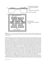
Schematics of a bubble immersed in a wetting liquid within a capillary of radius R are shown in Figure 13.1.
The dimensionless coordinate r is scaled by the capillary radius R. If the bubble is not translating, the cap-
illary pressure drop across the bubble cap is of order
σ
/R, where s is the interfacial tension. In contrast, the
pressure drop necessary to drive a liquid slug of length l at speed U in the same channel is of order Ul
µ
/R
2
.
Hence, the slug length l scales as RCa
Ϫ1
where Ca ϭ
µ
U/
σ
is the capillary number. In microchannels, Ca
ranges from 10
Ϫ8
to 10
Ϫ4
(for aqueous solutions moving at 10
Ϫ4
to 1 mm/sec), thus the equivalent slug
length l is many orders of magnitude higher than R. Equivalently, the capillary pressure across the static
meniscus can drive a liquid slug of length R at the astronomically large dimensionless speed of Ca ϭ 1.
For electrokinetic flow, such speeds can be achieved only by an electric field of more than 104 V/cm. The
capillary pressure across a static meniscus in a capillary, sometimes called the invasion pressure, is the
13-2 MEMS: Introduction and Fundamentals
1.0
0.5
0.0
r
0.00.0 0.5 1.0 1.5 2.0 2.5 3.00.0 0.5 1.0 1.5 2.0 2.5 3.0
X
Ca = 1 × 10
−4
1 × 10
−2
1 × 10
−1
1.0
0.5
0.0
r
1.0 2.0 3.0 4.0 5.0 6.0
−X
Ca = 1 × 10
−4
1 × 10
−2
1 × 10
−1
FIGURE 13.1 Front and back profiles for very long bubbles.
© 2006 by Taylor & Francis Group, LLC
Bubble/Drop Transport in Microchannels 13-3
required pressure to insert a meniscus in the capillary. After the bubble is set into motion, the required
pressure to sustain its motion is less than
σ
/R but is still significant.
The thickness of the wetting film around a moving bubble in a capillary and the pressure drop across the
wetting film were first studied by Bretherton (1961). For capillary radii R smaller than the capillary length
(
σ
/∆
ρ
g)
1/2
, which is about 1 mm for aqueous solutions, buoyancy effects are negligible, and the bubble is
axisymmetrically placed within the capillary. The flat annular film around the bubble allows only uni-
directional longitudinal flow. This lubrication limit stipulates that the pressure be constant across the film
and determined by the local interfacial curvature, the sum of the axial and azimuthal curvatures of the
axisymmetric bubble. Pressure variation is only in the longitudinal direction. For pressure-driven mobile
bubbles, the flat annular film at the middle of the drop indicates that no pressure gradient is present and
that there is no flow in the film. Liquid flow only occurs at the transition regions near the caps where the
film is no longer flat in the longitudinal direction. Near the front cap, the azimuthal curvature decreases
behind the tip, and the resulting capillary pressure gradient drives fluid into the annular film. The reverse
happens near the back cap to pick up the stagnant liquid laid down by the front cap. Unlike the usual
symmetric Stokes flow, the flow around the two caps are not mirror images of each other in
this free-surface problem. If they were reflectively symmetric, the net pressure drop across the bubble
would be zero, which is impossible for a translating bubble. The same negative bulk pressure gradient
results in pressure-driven liquid flow before and after the bubble. The capillary pressure gradients
at the two caps are in opposite directions relative to this bulk gradient. As a result, the two caps are not
mirror images of each other, and the capillary pressure across the back cap must be smaller than that at
the front cap.
Simple scaling arguments determine the pressure drop across the bubble and the thickness of the sur-
rounding film. The leading order estimate of capillary pressure drops at both caps is identical at 2
σ
/R, and
the axial curvature at the tips is 1/R. The axial curvature at the surrounding annular film is d
2
h/dx
2
, where
h is the interfacial thickness measured from the capillary wall and x is the longitudinal direction. (The
azimuthal curvature gradient scales as h
x
and is negligible compared to the axial curvature gradient h
xxx
in the short transition region.) Balancing the axial curvature d
2
h/dx
2
to 1/R reveals that the ratio of the
length of the transition region scales as the square root of the film thickness, with both lengths small com-
pared to the capillary radius R. The pressure gradient in the transition regions provided by the capillary
pressure drives a liquid flow at the speed U of the bubble. Balancing the viscous dissipation estimate
µ
U/h
2
with dp/dx and using the above scalings for each quantity, we conclude that the ratio of h
2
to the
transition length x is of order Ca. Reconciling this with the relative scalings imposed by curvature matching,
we obtain the classical Bretherton scalings — the film thickness scales as RCa
2/3
while the transition
regions near the cap are of the order of RCa
1/3
long, with Ca ϽϽ 1. The total viscous dissipation due to the
flow at the caps is the integral of
µ
times the normal gradient of the flow field at the wall over the transi-
tion length. This is the capillary pressure required to balance the dissipation. Using the previous scaling, this
capillary pressure is of the order (
σ
/R)Ca
2/3
. Due to the asymmetry of the two caps, this capillary pressure
is different at the two caps. The difference in the pressure drop across the two caps is then of the order
(
σ
/R)Ca
2/3
.
Using this new estimate for the pressure drop, we conclude that the equivalent slug length l scales as
RCa
Ϫ1/3
. Equivalently, in a train of translating bubbles spaced by continuous liquid slugs, the pressure
drop across each bubble roughly corresponds to a liquid slug of length RCa
Ϫ1/3
, or 10 to 1000 times the
capillary radius. Hence, the pressure drop required to drive most bubble trains occurs at the bubble caps.
Even without contact-line resistance, pressure-driven multiphase transport in microchannels is expected
to require orders of magnitude higher pressure drops. In the next section, we estimate this pressure drop with
and without Marangoni traction introduced by surfactants, and we sketch the effects of drop viscosity
and noncircular capillaries. It is unlikely that we can achieve pressure-driven multiphase flow under realistic
conditions. The following section shows that electrokinetically driven multiphase flow is achievable and
demonstrates that bubble speed can reach as high as the electrokinetic speed of pure liquids. Such flows occur
under very specific conditions, which are described in some detail. We conclude with some conjectures on
other multiphase microfluidics.
© 2006 by Taylor & Francis Group, LLC
13.3 The Bretherton Problem for Pressure-Driven Bubble/
Drop Transport
The previous scaling arguments can be made more precise with matched asymptotics. Using a local Cartesian
coordinate for the thin-film region, the usual lubrication analysis yields the following longitudinal velocity
profile:
u(y) ϭ
Ϫ yh
(13.1)
The normal coordinate y is measured from the capillary wall. The pressure p is independent of y and is
equal to Ϫ
σ
h
xx
, the axial curvature of the film. Hence, integrating over the film thickness, one obtains the
flow rate q ϭ
ᎏ
σ
3
h
µ
3
ᎏ
ᎏ
∂
∂
3
x
h
3
ᎏ
. The cubic power dependence arises from the parabolic profile of u(y) in Equation
(13.1). Mass balance over the entire film cross section yields:
ϭ Ϫ (13.2)
In a frame moving with the bubble speed U, the time derivative is converted into ϪUh
x
in the moving frame.
Integrating from the flat-film region where the third derivative vanishes into the transition region yields:
3
(h Ϫ h
ϱ
) ϭ h
3
h
xx
(13.3)
Scaling h by the unknown flat-film thickness h
ϱ
and scaling the x coordinate by h
ϱ
/(3Ca)
1/3
, we obtain the
Bretherton equation:
H
XXX
ϭ (13.4)
This nonlinear equation for H describes the transition regions of both caps. However, the front one
corresponds to X → ϱ, while the back one corresponds to X → Ϫϱ. The two asymptotic behaviors are
not identical, indicating that the two caps are not mirror images. Nevertheless, as H blows up in both
infinities, its third derivative must vanish according to Equation (13.4), and one expects quadratic
blowup in both directions. These quadratic asymptotes must then be matched to the outer cap solutions.
As h blows up, viscous effects become negligible and the outer caps are, to the leading order, just static
solutions of the Laplace–Young equation. Without gravitational effects, these axisymmetric solutions are
just spherical caps of radius R that make quadratic contact with the wall.
Linearizing about H ϭ 1, the behavior away from the flat film is governed by three eigenvalues, 1 and
Ϫ
ᎏ
1
2
ᎏ
Ϯ
ᎏ
͙
2
3
ෆ
ᎏ
i.
There is only monotonic blowup in the positive X direction due to a lone positive real eigenvalue.
A numerical integration of Equation (13.4) yields the front cap asymptote:
H(X → ϱ) ϭ
α
ϩ
X
2
ϩ
γ
ϩ
X ϩ
β
ϩ
(13.5)
The second coefficient can be changed due to an arbitrary shift of X but the quadratic coefficient is universal.
We then choose the origin of X until
γ
ϩ
vanishes. Equivalently, we can vary H Ϫ 1 with H
X
ϭ H
XX
ϭ 0
for the initial condition in our forward integration of Equation (13.4). This one-parameter iteration yields:
α
ϩ
ϭ 0.32171
β
ϩ
ϭ 2.898 (13.6)
Hence, the asymptotic curvature of the annular film toward the front cap is H
XX
ϭ 2
α
ϩ
or, in the origi-
nal dimensional coordinate:
h
xx
ϭ H
XX
ϭ (13.7)
2
α
ϩ
(3Ca)
2/3
ᎏᎏ
h
ϱ
(3Ca)
2/3
ᎏ
h
ϱ
H Ϫ 1
ᎏ
H
3
µ
U
ᎏ
σ
∂q
ᎏ
∂x
∂h
ᎏ
∂t
y
2
ᎏ
2
∂
3
h
ᎏ
∂
x
3
Ϫ
σ
ᎏ
µ
13-4 MEMS: Introduction and Fundamentals
© 2006 by Taylor & Francis Group, LLC
This must match with the front spherical cap of radius R that makes the quadratic tangent with the cap-
illary. Matching Equation (13.7) to this quadratic contact, we obtain the leading order estimate of the film
thickness:
h
ϱ
/R ϭ 0.6434(3Ca)
2/3
(13.8)
The back matching is more intricate. We note first that the complex eigenvalues suggest that the back
film is undulating. A pronounced dimple due to this undulation is evident in the back profiles of Figure 13.1
computed by Lu and Chang (1988). This film oscillation is indeed confirmed by the photographs of Friz
(1965). The arbitrary phase between these two complex modes must be specified. This extra degree
of freedom is not present for the positive direction with only one real eigenvalue. Due to the quadratic
contact of the back cap, we again iterate on the origin of X to obtain the back asymptote:
H(X → Ϫϱ) ϭ
α
Ϫ
X
2
ϩ
β
Ϫ
(13.9)
Because of the extra degree of freedom in the phase of the two complex conjugate modes, both
α
Ϫ
and
β
Ϫ
are functions of the phase, thus the pair (
α
Ϫ
,
β
Ϫ
) is a one-parameter family. To the leading order, this
asymptote must also match a sphere of radius R that makes tangential contact with the capillary. Hence,
α
Ϫ
ϭ
α
ϩ
ϭ 0.32171. For this value of
α
Ϫ
, the corresponding value of
β
Ϫ
is
β
Ϫ
ϭ Ϫ0.8415. (This is the
most accurate estimate obtained by Chang and Demekhin, 1999. It is slightly different from many earlier
values, including Bretherton’s.)
The capillary pressure drops at the two caps arise from the
β
Ϯ
terms. Consider the two spherical caps
of radius RЈ ϭ R(1 ϩ
ε
) different from the capillary radius R. Then, the expansion of the cap near the
contact point,
ᎏ
dh
d
(
x
0)
ᎏ
ϭ 0, is:
h ϳ Ϫ R
ε
(13.10)
Matching this expansion of the outer cap solution near the capillary to the two asymptotes of the inner
film solutions, Equations (13.5) and (13.9), the front cap has a radius smaller than R, and the back cap
has a larger radius. The difference is of order Ca
2/3
, the scalings for H in both equations. Hence, the pres-
sure drop across the entire bubble is the difference in the two cap capillary pressures
σ
/RЈ:
∆p/(
σ
/R) ϭ Ϫ ϳ 2(
ε
ϩ
Ϫ
ε
Ϫ
)
ϭ 2(
β
ϩ
Ϫ
β
Ϫ
)(h
ϱ
/R) ϭ 10.0Ca
2/3
(13.11)
The scaling of this pressure drop is consistent with the order-of-magnitude arguments of the previous
section. The unit-order coefficients are now specified by this classical matched asymptotic analysis. We note
that an inner X ln X asymptotic behavior needs to be matched to similar expansions in the outer solution
[Kalliadasis and Chang,1996]. Such high-order matching becomes important only when contact lines appear.
13.3.1 Corrections to the Bretherton Results for Pressure-Driven Flow
At higher values of Ca, between 0.01 and 0.1, the film thickness and pressure drop across the bubble must
be solved numerically instead of by matched asymptotics. This effort was carried out by Reinelt and Saffman
(1985) and Lu and Chang (1988). The pressure drop can be correlated up to Ca ϭ 0.1 as [Ratulowski and
Chang, 1989]:
∆
ρ
/(
σ
/R) ϭ 10.0Ca
2/3
Ϫ 12.6Ca
0.95
(13.12)
However, the capillary number rarely exceeds 10
Ϫ4
in microfluidics, and the Bretherton results of the pre-
vious section are usually adequate.
2
ᎏ
1 ϩ
ε
ϩ
2
ᎏ
1 ϩ
ε
Ϫ
x
2
ᎏ
R
Bubble/Drop Transport in Microchannels 13-5
© 2006 by Taylor & Francis Group, LLC
Bretherton finds his film thickness prediction to be smaller than the measured values at low Ca, exactly
where the matched asymptotic analysis is most valid. This is confirmed by a series of experiments sum-
marized by Ratulowski and Chang (1990), who attribute the deviation to Marangoni effects of surfactant
contaminants that are most pronounced at the thin films of low Ca. The film thickness is determined only
by how the front cap lays down a thin film by its capillary pressure. In this region, the film interface is
stretched considerably, and the interfacial surfactant concentration decreases from the cap to the film.
The film surface tension is then larger than the cap, and this Marangoni traction drags additional liquid
into the film to thicken it.
For soluble surfactants, a complex model involving bulk-interface transport must be constructed to
account for this new mechanism. For insoluble surfactants, a correction can be obtained almost trivially.
In the limit of very small Ca, this traction approaches infinity, and the free surface in the transition region
can be treated as a deformable but rigid interface that is laid onto the stagnant film. The velocity at the
rigid interface vanishes, and the parabolic velocity of Equation (13.1) becomes:
u(y) ϭ Ϫ
Ϫ
(13.13)
The flow rate q is then corrected by the factor of 4 due to the interface traction. The same correction yields
a factor of 4 to the left-hand side of the Bretherton equation, Equation (13.3). Simply scale Ca by 4 and
the same dimensionless Equation (13.4) results. Hence, in the limit of low Ca, soluble surfactants will correct
the film thickness by a factor of 4
2/3
. This asymptote is approached by the experimental data in Figure 13.2
at low Ca. Ratulowski and Chang show that these asymptotic values at infinite traction are also the
maximum values attainable for other more complex surfactant transport at low Ca. The correction to
yh
ᎏ
2
y
2
ᎏ
2
∂
3
h
ᎏ
∂
x
3
σ
ᎏ
µ
13-6 MEMS: Introduction and Fundamentals
FIGURE 13.2 The film thickness of a bubble translating in various surfactant solutions. The capillary number Ca is
a dimensionless speed, and the film thickness is scaled by the capillary radius. The theoretical curves correspond to
different surfactant equilibrium constants between the interface and the bulk. At low Ca, they all approach the same
asymptote derived in the text.
© 2006 by Taylor & Francis Group, LLC
pressure drop is more intricate because it requires the resolution of the entire bubble. Because the sur-
factants accumulate at the back cap (or near a stagnation point near the back cap), correction requires a
model for surfactant accumulation. Such a model was constructed by Park (1992) who then showed that
the pressure drop across the bubble now has a Ca
1/3
scaling due to the accumulation. The pressure drop,
increases by a factor of Ca
1/3
in the presence of surfactants.
One particularly interesting phenomenon concerning Marangoni effect is remobilization [Stebe et al.,
1991] at high bulk surfactant concentrations when the entire interface can saturate even as it is being
stretched. The Marangoni traction vanishes, and the mobile limit is again attained. This strategy reduces the
pressure drop by only a factor of order unity and does not change the basic scalings.
For bubble trains whose bubbles are separated by thin lamellae instead of spherical caps (see Figure 13.3),
Ratulowski and Chang (1989) show that the pressure drop remains constant to the leading order, while
the film thickness decreases as adjacent bubbles are compressed (larger contact radius r
c
in Figure 13.3.
Geometric considerations clarify that a larger compression between adjacent bubbles will decrease the
film thickness. An expansion of the Laplace–Young equation for the lamellae about zero contact radius
shows that the film thickness is related to the free bubble thickness at r
c
ϭ 0 by:
h
ϱ
(r
c
) ϭ (1 Ϫ r
c
)h
ϱ
(0) (13.14)
Because the lamella is a constant curvature axisymmetric surface, its contribution to the curvatures of
both asymptotes of the thin annular film is identical. The pressure drop across the bubble is independent
of the contact radius.
Schwartz et al. (1986) examine drop transport and find that the thickness and pressure drop increase
monotonically with respect to the viscosity ratio between the drop and the wetting fluid. The maximum
occurs at infinitely large viscosity, corresponding to a solid drop, and the maximum is found to be larger
than Bretherton’s result by a factor of 2
2/3
. The difference between this correction factor and the
Marangoni correction is a result of the differing films. The latter corresponds to a stationary rigid film
while the former corresponds to a translating film. The Bretherton scaling results are robust estimates for
circular capillaries. These estimates are only slightly corrected by Marangoni tractions due to surfactants,
drop viscosity, and even bubble spacing.
The Bretherton scaling arguments break down for noncircular channels. Ratulowski and Chang (1989)
examined the square channel numerically. Because the bubble caps of isolated bubbles are axisymmetric,
contact must be made with the wall at low Ca, which is estimated to be at Ca ϭ 0.04. Below this level,
contact lines are expected, and the liquid does not wet the channel wall. Thus, favorable operating con-
ditions only exist for Ca larger than 0.04, and the numerical results show that the film thickness and pres-
sure drop show peculiar scaling:
h
ϱ
ϭ 0.69 Ϫ 0.10 ln Ca ∆p/(
σ
/R) ϭ 3.14Ca
0.14
(13.15)
The radius R corresponds to a cylindrical capillary with the same cross-section area.
Bubble/Drop Transport in Microchannels 13-7
FIGURE 13.3 Schematic of a bubble train. The contact radius r
c
represents the degree of compression.
© 2006 by Taylor & Francis Group, LLC
Estimates for other channel geometries have not been computed, but the formulation by Ratulowski
and Chang can be used. Solve the following two-dimensional unit cell equation for each dimensionless
bubble radius r, scaled with respect to R:
∇
2
ψ
ϭϪ1 (13.16)
This fundamental solution is solved within a cross section of the straight capillary with a Dirichlet
boundary condition at the capillary wall and Neumann condition at the circular interface with the
dimensionless radius r.The flow rate–capillary pressure relation then becomes:
q ϭϪK ϭ K(r) (13.17)
The permeability constant K(r) is the cross-section average of the previous fundamental solution multiplied
by the factor
σ
R
4
/
µ
. A higher order version of the curvature can be used in place of the second derivative
of r.Toavoid contact between bubble and capillary, the capillary cross-section geometry must be nearly
axisymmetric. As a result, one does not expect the pressure drop to be significantly different from
Bretherton’s estimate for circular capillaries, despite the difference in Ca scaling.
13.4 Bubble Transport by Electrokinetic Flow
The large pressure drop required to drive multiphase microchannel flow suggests the electrokinetic driv-
ing force is more desirable. If the electrokinetic flow behind the bubble is larger than that of the sur-
rounding film, a high-pressure region can build up behind the bubble to drive it with the previously
mentioned capillary pressure mechanism. The task is reducing the flow around the bubble without cut-
ting the current required to drive the fluid. It is much easier to build the back pressure with electrokinetic
flow than with pressure-driven flow behind the bubble because the required driving force is not as large.
This is in direct contrast to single-phase channel flow where the hydrodynamic stress of the electrokinetic
flow is confined to the thin double layer. As a result, the efficiency of single-phase electrokinetic flow is
much lower than that of pressure-driven flow.
This design consideration requires some knowledge of electrokinetic flow [Russel et al., 1989;
Probstein, 1994]. Electrokinetic flow occurs when the dielectric channel wall contains some surface
charges that attract co-ions of opposite charge in the solution to a thin double layer of thickness
λ
.Also
known as the Debye length,
λ
,ranges from 10 nm to microns depending on the bulk electrolyte concen-
tration. The counter-ion concentration increases from the bulk value toward the wall within this double
layer, while the co-ion decreases from its bulk value. Both bulk values are identical due to charge
neutrality, therefore a net charge exists within the thin double layer. The total amount of this charge is
determined through ionization equilibrium by the surface charge on the capillary.
Within the double layer, the potential
φ
is governed by the Poisson equation:
ϭ (13.18)
The charge density is
ρ
, and the potential is set to zero at the bulk when y approaches infinity. The poten-
tial at the surface is called the zeta potential
ζ
.Due to the Boltzmann distributions of the co-ion and counter-
ion, the counter-ion concentration increases much faster than the co-ion concentration decreases toward
the wall. As a result, the total ion concentration in the double layer exceeds that in the bulk by a factor of
exp(
ζ
/kT), as seen in Figure 13.4. The charge density
ρ
also increases from zero at the bulk to a value at
the wall equal to the bulk concentration multiplied by exp(
ζ
/kT). Hence, at low
ζ
/kT, Equation (13.18)
indicates that the scaling for
λ
is inversely proportional to the square root of the bulk ion concentration.
By integrating Equation (13.18) over the double layer, its total charge scales linearly with respect to the
F
ρ
ᎏ
ε
∂
2
φ
ᎏ
∂y
2
∂
3
r
ᎏ
∂
x
3
∂p
ᎏ
∂
x
13-8 MEMS: Introduction and Fundamentals
© 2006 by Taylor & Francis Group, LLC
potential gradient at the wall. The latter quantity scales as
ζ
/
λ
. One concludes that, for a given
capillary–electrolyte pair, the zeta potential
ζ
scales as
λ
, inversely as the square root of the bulk
electrolyte concentration.
In the presence of a tangential electric field E, there is a net body force on the electrolyte that scales as
E
ρ
. This body force vanishes in the neutral bulk but accelerates the ions in the double layer to large
speeds. These streaming ions drag the entire fluid body in the capillary along with them. The body force
is concentrated in the thin double layer and acts like a surface force. The entire bulk liquid translates
rigidly with a uniform tangential velocity, assuming there is no external pressure gradient. The momen-
tum transfer in y for the tangential velocity field involves the viscous dissipation term (
µ
d
2
u/d
2
y) balanced
by the body force E
ρ
. Because this is in the same form as the Poisson equation, one sees that u scales lin-
early with respect to the electric potential
φ
but approaches a constant value away from the double layer.
This asymptote is called the electrokinetic velocity:
u
c
ϭ Ϫ (13.19)
The constants
ε
0
and
ε
are the dielectric permittivities that we have omitted in the previous scaling
arguments.
Because the electrokinetic velocity is flat away from the thin double layer (see Figure 13.4), the flow
rate scales as the cross-section area, or R
2
. For pressure-driven flow, the flow rate scales as the square of
the area, or R
4
. The electrokinetic velocity is independent of R, whereas the velocity of pressure-driven
flow scales as the second power of R. Electrokinetic flow is much less efficient than pressure-driven flow,
but electrokinetic flow is easier to scale up and down in microfluidic designs.
Unfortunately, the same flat electrokinetic velocity profile now serves to prevent cessation of film flow.
By simple current–voltage calculation in the longitudinal direction, the local electric field E is shown to
scale as the inverse of the cross-section area of the electrolyte across the capillary. By Equation (13.19),
ε
0
εζ
c
E
ᎏ
µ
Bubble/Drop Transport in Microchannels 13-9
U
b
U
eo
V
(a)
U
f
C
o
C
s
Air - liquid boundary
Glass capillary
0 < ζ
b
< ζ
c
ζ
b
< 0
ζ
c
> 0
(
b
)
FIGURE 13.4 Electrokinetically driven bubble transport. The electrolyte ion concentration profile C
0
is shown with
the velocity profiles U
f
for both negative and positive zeta potentials at the bubble interface. The bubble translates with
bubble speed U
b
and the liquid with electrokinetic velocity U
eo
.
© 2006 by Taylor & Francis Group, LLC
the electrokinetic velocity scales the same way. However, the flow rate scales as the electrokinetic velocity
times the cross-section area and is independent of the cross-section area. The flow rate behind the bubble
is the same as the flow rate in its surrounding film. As a result, there is no back pressure buildup, and the
electrolyte simply flows around the bubble. This is observed when air bubbles are driven electrokinetically
in a KCl/H
2
SO
4
electrolyte (about 10
Ϫ2
and 10
Ϫ6
mol/L each) in a 5-cm-long glass capillary with a 1.0-mm
inner diameter and with a voltage drop of 30 to 70 V [Takhistov et al., 2000]. At these conditions, the elec-
trokinetic velocity of the electrolyte is 0.1 to 1.0mm/sec, yet the bubble remains stationary as the electrolyte
flows past it.
There are several possible means of breaking the flow rate invariance to cross-section area in order to
reduce the film flow. One can endow the interface with traction by using finite viscosity drops or interfacial
surfactants so that the film profile is no longer flat. The longitudinal electric field in the film can be reduced
by lowering the electrolyte concentration such that the thickened double-layer thickness approaches that
of the film. As a result, the higher ion concentration within the double layer can increase the film conduc-
tivity beyond the bulk value. More intriguingly, one can use an ionic surfactant to endow a double layer at
the interface that has a different charge from the capillary double layer. The velocity at the interface is not zero
in the moving frame but is negative (see Figure 13.4). This could effectively reduce the film flow to zero.
The surfactants act as a valve to film flow that requires no pressure expenditure and film flow leakage.
The bubble front does not produce a pressure drop that counters the one in the back of the bubble. In
contrast, the Bretherton problem in pressure-driven bubble flow requires a near-cancellation of these
pressure drops, resulting in the small pressure buildup of Equation (13.12) and a similarly small bubble
velocity. Takhistov et al. (2002) have experimentally established this major advantage of displacing air
bubbles with electrokinetic flow.
Because the glass capillary surface of Takhistov et al.’s e x p er iment has a positive charge such that its
double layer contains a negative charge, an anionic surfactant, sodium dodecyl sulfate (SDS), tests the
previous idea. Most glass surfaces are negatively charged, but the charge is reversed through chemical
treatment to allow an interfacial double layer of the opposite charge. About 10
Ϫ5
mol/L of the surfactant is
added and, after some equilibration time, the bubbles begin to move. In Figure 13.5, the measured bubble
13-10 MEMS: Introduction and Fundamentals
FIGURE 13.5 Electrokinetically driven bubble speed as a function of a concentration-normalized electric field for
the KCl electrolyte of indicated concentrations. The unnormalized data scatter over 5 decades and are collapsed by
the theory.
© 2006 by Taylor & Francis Group, LLC