Micro Electro Mechanical System Design - James J. Allen Part 2 pot
Bạn đang xem bản rút gọn của tài liệu. Xem và tải ngay bản đầy đủ của tài liệu tại đây (1016.61 KB, 30 trang )
Introduction 9
The automotive market is a mass market in which MEMS is playing an ever
increasing role. For example, 90 million air bag accelerometers and 30 million
manifold absolute pressure sensors were supplied to the automotive market in
2002 [30].
Another mass market in which MEMS has an increasing impact is the bio-
logical medical market. MEMS technology enables the production of a device of
the same scale as biological material. Figure 1.2 shows a comparison of a MEMS
device and biological material. An example of MEMS’ impact on the medical
market is the DNA sequencing chip, GeneChip, developed by Affymetrix Inc.
[31], which allows medical testing in a fraction of the time and cost previously
available. In addition, MEMS facilitates direct interaction at the cellular level
[32].
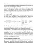
Figure 1.3 shows cells in solution flowing through the cellular manipulator,
which could disrupt the cell membrane to allow easier insertion of genetic and
chemical materials. Also shown in Figure 1.3 are chemical entry and extraction
ports that allow the injection of genetic material, proteins, etc. for processing in
TABLE 1.6
MEMS Applications
Device Use
Pressure sensors Automotive, medical, industrial
Accelerometer Automotive and industrial motion sensing
Gyroscope Automotive and industrial motion sensing
Optical displays Cinema and business projectors, home theater, television
RF devices Switches, variable capacitors, filters
Robotics Sensing, actuation
Biology and medicine Chemical analysis, DNA sequencing, drug delivery,
implantable prosthetics
FIGURE 1.2 MEMS device and biological material comparison. (Courtesy of Sandia
National Laboratories.)
Red Blood
Cells
Pollen
50 µ
5
© 2005 by Taylor & Francis Group, LLC
10 Micro Electro Mechanical System Design
a continuous fluid flow system. An additional illustration of the impact of MEMS
that would have been thought to be science fiction a few years ago is the retinal
prosthesis [33] under development that will enable the blind to see.
MEMS also has a significant impact on space applications. The miniaturization
of sensors is an obvious application of MEMS. The use of MEMS for thermal
control of microsatellites is somewhat unanticipated. MEMS louvers [34] are
micromachined devices similar in function and design to conventional mechanical
louvers used in satellites; here, a mechanical vane or window is opened and closed
to vary the radiant heat transfer to space. MEMS is applicable in this context
because it is small and consumes little power, but produces the physical effect of
variable thermal emittance, which controls the temperature of the satellite. The
MEMS louver consists of an electrostatic actuator that moves a louver to control
the amount of gold surface exposed (i.e., variable emittance).
Figure 1.4 shows the
MEM louvers that will be demonstrated on an upcoming NASA satellite mission.
The integration of MEMS devices into automobiles or satellites enables
attributes such as smaller size, smaller weight, and multiple sensors. The use of
MEMS in systems can also allow totally different functionality. For example, a
miniature robot with a sensor, control circuitry, locomotion, and self-power can
be used for chemical or thermal plume detection and localization [35]. In this
case, MEMS technology enables the group behavior of a large number of small
robots capable of simple functions. The group interaction (“swarming”) of these
simple expendable robots is used to search an area to locate something that the
sensor can detect, such as a chemical or temperature.
One vision of the future direction of MEMS is expressed in Picraux and
McWhorter [36], who propose that MEMS applications will enable systems to
think, sense, act, communicate, and self-power. Many of the applications dis-
cussed in this section indeed integrate some of these attributes. For example, the
FIGURE 1.3 Red blood cells flowing through a cellular manipulator with chemical
entry/extraction ports. (Courtesy of Sandia National Laboratories.)
© 2005 by Taylor & Francis Group, LLC
Introduction 11
small robot shown in Figure 1.5 has a sensor, can move, and has a self-contained
power source. To integrate all of these functions on one chip may not be practical
due to financial or engineering constraints; however, integration of these functions
via packaging may be a more viable path.
MEMS is a new technology that has formally been in existence since the
1980s when the acronym MEMS was coined. This technology has been focusing
on commercial applications since the mid 1990s with significant success [37].
The MEMS commercial businesses are generally organized around three main
models: MEMS manufacturers; MEMS design; and system integrators. In 2003,
368 MEMS fabrication facilities existed worldwide, with strong centers in North
America, Japan, and Europe. There are 130 different MEMS applications in
production consisting of a few large-volume applications in the automotive (iner-
FIGURE 1.4 MEMS variable emittance lover for microsatellite thermal control. The
device was developed under a joint project with NASA, Goddard Spaceflight Center, The
Johns Hopkins Applied Physics Laboratory, and Sandia National Laboratories.
FIGURE 1.5 A small robot with a sensor, locomotion, control circuitry, and self power.
(Courtesy of Sandia National Laboratories.)
© 2005 by Taylor & Francis Group, LLC
12 Micro Electro Mechanical System Design
tial, pressure); ink-jet nozzles; and medical fields (e.g., Affymetrix GeneChip).
The MEMS commercial market is growing at a 25% annual rate [37].
1.4 MEMS CHALLENGES
MEMS is a growing field applicable to many lines of products that has been
synergistically using technology and tools from the microelectronics industry.
However, MEMS and microelectronics differ in some very fundamental ways.
Table 1.7 compares the devices and technologies of MEMS and microelectronics,
and
Figure 1.6 compares the levels of device integration of MEMS and micro-
electronics. The most striking observation is that microelectronics is an enormous
industry based on a few fundamental devices with a standardized fabrication
process. The microelectronics industry derives its commercial applicability from
the ability to connect a multitude of a few fundamental types of electronic devices
(e.g., transistors, capacitors, resistors) reliably on a chip to create a plethora of
new microelectronic applications (e.g., logic circuits, amplifiers, computer pro-
cessors, etc.). The exponential growth predicted by Moore’s law comes from
improving the fabrication tools to make increasingly smaller circuit elements,
which in turn enable faster and more complex microelectronic applications.
The MEMS industry derives its commercial applicability from the ability to
address a wide variety of applications (accelerometers, pressure sensors, mirrors,
fluidic channel); however, no one fundamental unit cell [38,39] and standard
fabrication process to build the devices exists. In fact, the drive toward smaller
devices for microelectronics, which increased speed and complexity, does not
necessarily have the same impact on MEMS devices [40] due to scaling issues
(
Chapter 4). MEMS is a new rapidly growing [37] technology area in which
contributions are to be made in fabrication, design, and business.
TABLE 1.7
Comparison of MEMS and Microelectronics
Criteria Microelectronics MEMS
Feature size Submicron 1–3 µm
Device size Submicron ~50 µm–1 mm
Materials Silicon based Varied (silicon, metals, plastics)
Fundamental devices Limited set: transistor,
capacitor, resistor
Widely varied: fluid, mechanical, optical,
electrical elements (sensors, actuators, switches,
mirrors, etc.)
Fabrication process Standardized: planar
silicon process
Varied: three main categories of MEMS
fabrication processes plus variants:
Bulk micromachining
Surface micromachining
LIGA
© 2005 by Taylor & Francis Group, LLC
Introduction 13
1.5 THE AIM OF THIS BOOK
This book is targeted at the practicing engineer or graduate student who wants
an introduction to MEMS technology and the ability to design a device applicable
to his or her area of interest. The book will provide an introduction to the basic
concepts and information required to engage fellow professionals in the area
and will aid in the design of a MEMS product that addresses an application
area. MEMS is a very broad technical area difficult to address in detail within
one book due to this breadth of material. It is the hope that this text coupled
with an engineering or science educational background will enable the reader
to become a MEMS designer. The chapters (topics) of this book are organized
as follows. They can be taken in whole or as needed to fill the gaps in an
individual’s background.
•
Chapter 2: Fabrication Processes — offers an overview of the individ-
ual fabrication process applicable to MEMS.
•
Chapter 3: MEMS Technologies — is an overview of the combination
of fabrication processes necessary to produce a technology suitable for
the production of MEMS devices and products.
•
Chapter 4: Scaling Issues for MEMS — covers the physics and device
operation issues that arise due to the reduction in size of a device.
•
Chapter 5: Design Realization Tools for MEMS — discusses the com-
puter-aided design tools required to interface a design with the fabri-
cation infrastructure encountered in MEMS.
•
Chapter 6: Electromechanics — provides an overview of the physics
of electromechanical systems encountered in MEMS design.
•
Chapter 7: Modeling and Design — is an introduction to modeling for
MEMS design with an emphasis on low-order models for design
synthesis.
•
Chapter 8: MEMS Sensors and Actuators — offers an overview of
sensors and actuators utilized in MEMS devices.
FIGURE 1.6 Levels of device integration of MEMS vs. microelectronics.
© 2005 by Taylor & Francis Group, LLC
14 Micro Electro Mechanical System Design
• Chapter 9: Packaging — is a review of the packaging processes and
how the packaging processes and fabrication processes interact; three
packaging case studies are presented.
•
Chapter 10: Reliability — covers the basic concepts of reliability and
the aspects of reliability unique to MEMS, such as failure mechanisms
and failure analysis tools.
QUESTIONS
1. Use the Web as a tool to explore what is happening in the world of
MEMS.
2. Pick an application and research how it is used. What type of fabrication
process is used and how many companies have products in this area?
3. Look at a MEMS application that existed before MEMS technology
existed. How did MEMS technology have an impact on this application
in performance, cost, or volume production?
REFERENCES
1. D. Sobel, Longitude, The True Story of a Lone Genius Who Solved the Greatest
Scientific Problem of His Time, Penguin Books, New York, 1995.
2. J. Bardeen, W. H. Brattain, The transistor, a semiconductor triode, Phys. Rev., 74,
130–231, 1948.
3. W. Shockley, A unipolar field-effect transistor, Proc. IRE, 40, 1365, 1952.
4. ENIAC (electronic numerical integrator and computer) U.S. Patent No. 3,120,606,
filed 26 June 1947.
5. ENIAC Museum:
/>6. J.A. Hoerni, Planar silicon transistors and diodes, IRE Transactions Electron
Devices, 8, 2, March 1961.
7. J.A. Hoerni, Method of manufacturing semiconductor devices, U.S. Patent
3,025,589, issued March 20, 1962.
8. J.S. Kilby, Miniaturized electronic circuits, U.S. Patent 3,138,743, filed February
6, 1959.
9. R.N. Noyce, Semiconductor device and lead structure, U.S. Patent 2,918,877, filed
July 30, 1959.
10. G.E. Moore, Cramming more components onto integrated circuits, Electronics,
38(8), April 19, 1965.
11. R.P. Feynman, There’s plenty of room at the bottom, Eng. Sci. (California Institute
of Technology), February 1960, 22–36.
12. R.P. Feynman, There’s plenty of room at the bottom, JMEMS, 1(1), 60–66, March
1992.
13. R.P. Feynman, There’s plenty of room at the bottom,
/>nanotech/feynman.html.
14. E. Regis, Nano: The Emerging Science of Nanotechnology, Little, Brown and
Company, New York, 1995.
15. N. Maluf, An Introduction to Microelectromechanical Systems Engineering,
Artech House Inc., Boston, 2000.
© 2005 by Taylor & Francis Group, LLC
Introduction 15
16. The Caltech Institute Archives:
/>17. Pease Group Homepage:
/>18. C.S. Smith, Piezoresistive effect in germanium and silicon, Phys. Rev. 94(1),
42–49, April, 1954.
19. J.D. Meindel, Q. Chen, J.A. Davis, Limits on silicon nanoelectronics for terascale
integration, Science, 293, 2044–2049, September 2001.
20. H.C. Nathanson, W.E. Newell, R.A. Wickstrom, J.R. Davis, The resonant gate
transistor, IEEE Trans. Electron Devices, ED-14, 117–133, 1967.
21. K.E. Petersen, Silicon as a mechanical material, Proc. IEEE, 70(5), 420–457, May
1982.
22. R.T. Howe and R.S. Muller, Polycrystalline silicon micromechanical beams, J.
Electrochem. Soc.: Solid-State Sci. Technol., 130(6), 1420–1423, June 1983.
23. L-S. Fan, Y-C Tai, R.S. Muller, Integrated movable micromechanical structures
for sensors and actuators, IEEE Trans. Electron Devices, 35(6), 724–730, 1988.
24. W.C. Tang, T.C.H. Nguyen, R.T. Howe, Laterally driven polysilicon resonant
microstructures, Sensors Actuators, 20(1–2), 25–32, November 1989.
25. K.S.J. Pister, M.W. Judy, S.R. Burgett, R.S. Fearing, Microfabricated hinges,
Sensors Actuators A, 33, 249–256, 1992.
26. E.W. Becker, W. Ehrfeld, P. Hagmann, A. Maner, and D. Muchmeyer, Fabrication
of microstructures with high aspect ratios and great structural heights by synchro-
tron radiation lithography, galvanoforming, and plastic molding (LIGA process),
Microelectron. Eng., 4, 35, 1986.
27. Analog Devices IMEMS technology:
/>28. Texas Instrument DLP™ technology:
/>29. D. Forman, Automotive applications, smalltimes, 3(3), 42–43, May/June 2003.
30. R. Grace, Autos continue to supply MEMS “killer apps” as convenience and safety
take a front seat, smalltimes, 3(3), 48, May/June 2003.
31. Affymetrix, Inc.
GeneChip.
32. M. Okandan, P. Galambos, S. Mani, J. Jakubczak, Development of surface micro-
machining technologies for microfluidics and BioMEMS, Proc. SPIE, 4560,
133–139, 2001.
33. D. Sidawi, Emerging prostheses attempt vision restoration, R&D Mag., 46(6),
30–32, June 2004.
34. R. Osiander, J. Champion, A. Darrin, D. Douglass, T. Swanson, J. Allen, E.
Wyckoff, MEMS shutters for spacecraft thermal control, NanoTech 2002, Hous-
ton, TX. 9–12 September 2002.
35. R. H. Byrne, D. R. Adkins, S. E. Eskridge, H. H. Harrington, E. J. Heller, J. E.
Hurtado, Miniature mobile robots for plume tracking and source localization
research, J. Micromechatronics, 1(3), 253–261, 2002.
36. S.T. Picraux and P.J. McWhorter, The broad sweep of integrated microsystems,
IEEE Spectrum, 35(12), 24–33, December 1998.
37. MEMS not so small after all, Micro Nano, 8(8), 6, Aug 2003
38. M.W. Scott and S.T. Walsh, Promise and problems of MEMS or nanosystem unit
cell, Micro/Nano Newslett., 8(2), 8, February 2003.
39. M. Scott, MEMS and MOEMS for national security applications, Proc. SPIE,
4979, 26–33, 2003.
40. S.D. Senturia, Microsensors vs. ICs: a study in contrasts, IEEE Circuits Devices
Mag., 20–27, November 1990.
© 2005 by Taylor & Francis Group, LLC
17
2
Fabrication Processes
This chapter will present an overview of the various processes used in the
fabrication of MEMS devices. The first section will present an introduction to
materials and their structure. The processes that will be discussed in subsequent
sections include deposition, patterning, and etching of materials as well as pro-
cesses for annealing, polishing, and doping, which are used to achieve special
mechanical, electrical, or optical properties. Many of the processes used for
MEMS are adapted from the microelectronics industry; however, the conceptual
roots for some of the fabrication processes (e.g., sputtering, damascene) signifi-
cantly predate that industry.
2.1 MATERIALS
2.1.1 INTERATOMIC BONDS
The material structure type is greatly influenced by the interatomic bonds and
their completeness. There are three types of interatomic attractions: ionic bonds,
covalent bonds, and metallic bonds (
Figure 2.1). The ionic bonds occur in
materials where the interatomic attractions are due to electrostatic attraction
between adjacent ions. For example, a sodium atom (Na) has one electron in its
valence shell (i.e., outer electron shell of an atom), which can be easily released
to produce a positively charge sodium ion (Na
+
). A chlorine atom (Cl) can readily
accept an electron to complete its valence shell, which will produce a negatively
charged chlorine ion (Cl
–
). The electrostatic attraction of an ionic bond will cause
the negatively charged chlorine ion to surround itself with positively charged
sodium ions.
The electronic structure of an atom is stable if the outer valence shells are
complete. The outer valence shell can be completed by sharing electrons between
adjacent atoms. The covalent bond is the sharing of valence electrons. This bond
is a very strong interatomic force that can produce molecules such as hydrogen
(H
2
) or methane (CH
4
), which have very low melting temperature and low attrac-
tion to adjacent molecules, or diamond, which is a covalent bonded carbon crystal
with a very high melting point and great hardness. The difference between these
two types of covalent bonded materials (i.e., CH
4
vs. diamond) is that the covalent
bond structure of CH
4
completes the valence shell of the component atoms within
one molecule, whereas the valence shell of the carbon atoms in diamond are
© 2005 by Taylor & Francis Group, LLC
18 Micro Electro Mechanical System Design
completed via a repeating structure of a large number of carbon atoms (i.e.,
crystal/lattice structure).
A third type of interatomic bond is the metallic bond. This type of bond
occurs in the case when only a few valence electrons in an atom may be easily
removed to produce a positive ion (e.g., positively charged nucleus and the
nonvalence electrons) and a free electron. Metals such as copper exhibit this type
of interatomic bond. Materials with the metallic bond have a high electrical and
thermal conductivity.
Another, weaker group of bonds is called van der Waals forces. The mech-
anisms for these forces come from a variety of mechanisms arising from the
asymmetric electrostatic forces in molecules, such as molecular polarization due
to electrical dipoles. These are very weak forces that frequently only become
significant or observable when the ionic, covalent, or metallic bonding mecha-
nisms cannot be effective. For example, ionic, covalent, and metallic bonding is
not effective with atoms of the noble gases (e.g., helium, He), which have
complete valence electron shells, and rearrangements of the valence electrons
cannot be done.
2.1.2 MATERIAL STRUCTURE
The atomic structure of materials can be broadly classified as crystalline, poly-
crystalline, and amorphous (illustrated in
Figure 2.2). A crystalline material has
a large-scale, three-dimensional atomic structure in which the atoms occupy
specific locations within a lattice structure. Epitaxial silicon and diamond are
examples of materials that exhibit a crystalline structure. A polycrystalline mate-
rial consists of a matrix of grains, which are small crystals of material with an
interface material between adjacent grains called the grain boundary. Most metals,
such as aluminum and gold, as well as polycrystalline silicon, are examples of
this material structure.
The widely used metallurgical processes of cold working and annealing
greatly affect the material grains and grain boundary and the resulting material
properties of strength, hardness, ductility, and residual stress. Cold working uses
FIGURE 2.1 Simplified representation of interatomic attractions of the ionic bond, cova-
lent bond, metallic bond.
(
( (
)
) )
© 2005 by Taylor & Francis Group, LLC
Fabrication Processes 19
mechanical deformation to reduce the material grain size; this will increase
strength and hardness, but reduce ductility. Annealing is a process that heats the
material above the recrystallization temperature for a period of time, which will
increase the grain size. Annealing will reduce residual stress and hardness and
increase material ductility. A noncrystalline material that exhibits no large-scale
structure is called amorphous. Silicon dioxide and other glasses are examples of
this structural type.
2.1.3 CRYSTAL LATTICES
The structure of a crystal is described by the configuration of the basic repeating
structural element, the unit cell. The unit cell is defined by the manner in which
space within the crystal lattice is divided into equal volumes using intersecting
plane surfaces. The crystal unit cell may be in one of seven crystal systems. These
crystal systems are cubic; tetragonal; orthorhombic; monoclinic; triclinic; hex-
agonal; and rhombohedral. They include all the possible geometries into which
a crystal lattice may be subdivided by the plane surfaces. The crystalline material
structure is greatly influenced by factors such as the number of valance electrons
and atomic radii of the atoms in the crystal (
Table 2.1). The cubic crystal system
is a very common and highly studied system that includes most of the common
engineering metals (e.g., iron, nickel, copper, gold) as well as some materials
used in semiconductors (e.g., silicon, phosphorus).
The cubic crystal system has three common variants: simple cubic (SC), body-
centered cubic (BCC), and face-centered cubic (FCC), which are shown in
Figure
2.3
. The properties of crystalline material are influenced by the structural aspects
of the crystal lattice, such as the number of atoms per unit cell; the number of
atoms in various directions in the crystal; and the number of neighboring atoms
within the crystal lattice, as shown in
Table 2.2. The unit cells depicted are shown
with the fraction of the atom that would be included in the unit cell (i.e., the
simple cubic has one atom per unit cell; the body-centered cubic has two atoms
per unit cell; face-centered cubic has four atoms per unit cell). As can be surmised,
FIGURE 2.2 Schematic representation of crystalline, polycrystalline, and amorphous
material structures.
Grain
(a) Crystalline (b) Polycrystalline (c) Amorphous
Grain Boundary
© 2005 by Taylor & Francis Group, LLC
20 Micro Electro Mechanical System Design
TABLE 2.1
Atomic and Crystal Properties for Selected Elements
Element
Atomic
number
Atomic mass
(g/g-atom) Crystal Valence
Atomic
radius (Å)
Boron (B) 5 10.81 Orthorhombic 3 0.46
Aluminum (Al) 13 26.98 FCC 3 1.431
Silicon (Si) 14 28.09 Diamond 4 1.176
Phosphorus (P) 15 30.97 Cubic 5 —
Iron (Fe) 26 55.85 BCC 2 1.241
Nickel (Ni) 28 58.71 FCC 2 1.245
Copper (Cu) 29 63.54 FCC 1.278
Gallium (Ga) 31 69.72 Ortho 3 1.218
Germanium (Ge) 32 72.59 Diamond 4 1.224
Arsenic (As) 33 74.92 Rhombic 5 1.25
Indium (In) 49 114.82 Tetra 3 1.625
Antimony (Sb) 51 121.75 Rhombic 5 1.452
Tungsten (W) 74 183.9 BCC — 1.369
Gold (Au) 79 197.0 FCC — 1.441
Notes: BCC — body-centered cubic; FCC — face-centered cubic.
FIGURE 2.3 Cubic crystal structures.
TABLE 2.2
Properties of Different Forms of the Cubic Lattice
Crystal structure
Number of
nearest neighbors Atoms/Cell
Packing factor
a
(atom vol/cell vol)
Cubic 6 1 0.52
Body-centered cubic 8 2 0.68
Face-centered cubic 12 4 0.74
Diamond cubic 4 8 —
a
Assuming only one atom type in the lattice.
(a) Simple Cubic (b) Body-Centered Cubic (c) Face-Centered Cubic
Y
Y
Y
Z
Z
Z
X
X
X
© 2005 by Taylor & Francis Group, LLC
Fabrication Processes 21
the crystal structure and the unit cell size (i.e., lattice constant) will greatly
influence the density of the material. For example, dense materials such as metals
crystallize in the body-centered cubic (e.g., iron, tungsten) or the face-centered
cubic (e.g., aluminum, cooper, gold, nickel), which contain more atoms per unit
cell instead of the simple cubic crystal, which contains only one atom per unit cell.
Silicon and germanium are Group IV elements on the periodic table; these
have four valence electrons and need four more electrons to complete the outer
electron shell. This can be accomplished by forming covalent bonds with four
nearest neighbor atoms in the lattice. However, none of the basic cubic lattice
forms have four nearest neighbors (
Table 2.2). Elements such as silicon and
germanium form a diamond structure, which can be conceptually thought of as
two interlocking face-centered cubic lattices with a one-fourth lattice constant
diagonal offset. This means that the diamond cubic lattice has four additional
atoms within a face-centered cubic-like lattice structure (Figure 2.4). The gallium
arsenide and indium phosphide compounds also use a version of the diamond
cubic lattice, called the zincblende, which has a reduced level of symmetry due
to the different atom sizes. Every atom in the diamond cubic lattice is tetrahedrally
bonded to its four neighbors. For example, in the zincblende lattice, each gallium
atom is tetrahedrally bonded to four arsenic atoms, and each arsenic atom is
tetrahedrally bonded to four gallium atoms.
The properties of crystalline materials such as mechanical strength or chem-
ical etch rates are affected by the lattice structure, and they may depend upon
the directionality of the lattice structure. For example, a cubic lattice is uniform
in all directions (i.e., the same number of atoms on any plane or in any direction).
However, the diamond lattice has a different number of atoms in any plane or
direction. The anisotropy of silicon material properties and etch rates can be
somewhat attributed to its crystal structure.
2.1.4 MILLER INDICES
The Miller indices is nomenclature to express directions or planes in a crystal
structure.
Figure 2.5 shows the Miller index notation for direction in a orthor-
hombic lattice. An orthorhombic lattice is defined by orthogonal planes spaced
differently in each direction. Miller index notation is based on the lattice unit cell
intercepts within square brackets (e.g., [1 1 1]) vs. the Cartesian distances. For
FIGURE 2.4 The diamond cubic lattice can be formed by adding four atoms (shaded
dark) to the face-centered cubic lattice.
© 2005 by Taylor & Francis Group, LLC
22 Micro Electro Mechanical System Design
example, the Miller index [1 1 1] denotes the direction from the origin of the
unit cell through the opposite corner of the unit cell (i.e., not the Cartesian
direction vector; Figure 2.5). Note that the [2 2 2] direction is identical to the [1
1 1] direction and the lowest combination of integers is used (e.g., [1 1 1]).
The planes within a lattice also need to be identified. The planes are denoted
with labels within curved brackets — e.g., (1 0 0) — as illustrated in Figure 2.6.
The (1 0 0) plane is orthogonal to the [1 0 0] direction. The numbers used in the
Miller notation for planes are the reciprocals of the intercepts of the axes in unit
cell distances from the origin. The Miller index notation includes not only the
(1 0 0) plane shown in Figure 2.6, but also all equivalent planes. In a simple cubic
lattice structure, the point of origin is arbitrarily chosen, and the (1 0 0) plane
FIGURE 2.5 Crystal directions in an orthorhombic lattice.
FIGURE 2.6 Crystal plane directions utilizing Miller indices.
[ i j k ] – direction
( i j k ) – plane
x
y
z
b a
c
[010]
[001]
(001)(001)
(010)(010)
(100)
[100][100]
© 2005 by Taylor & Francis Group, LLC
Fabrication Processes 23
will have the same properties as the (0 1 0) and the (0 0 1) planes. The (1 0 0)
refers to all three planes. Conversely, in an orthorhombic lattice, the planes (1 0 0),
(0 1 0), and (0 0 1) are unique.
2.1.5 CRYSTAL IMPERFECTIONS
The symmetry of the crystal is broken at the surface of the material. The atoms
at the surface are not bound to the other atoms in the same way as the bulk
material. Therefore, the surface will behave differently than the bulk crystal. For
example, the surface can chemically react and form an oxide or the surface can
become electrically charged. Integrated circuit manufacturers frequently build the
circuits upon a single-crystal silicon wafer with a (100) orientation (i.e., the [100]
plane is the wafer surface) because this orientation minimizes surface charges.
In addition to the surface differences, imperfections in the crystal lattices can
also be found. These can influence many characteristics of the material such as
mechanical strength, electrical properties, and chemical reactivity. The lattice
imperfections can be due to missing, displaced, or extra atoms in the lattice,
which are called point defects. Line defects have an edge due to an extra plane
of atoms.
Figure 2.7 illustrates several types of point defects, which include substitu-
tional, vacancy, and interstitial types of defects. A substitutional defect is due to
an impurity atom occupying a lattice site for the bulk material. In a vacancy
defect, a lattice site is not occupied. An interstitial defect involves an atom of
the bulk material or an impurity atom occupying space between the lattice sites.
These defects can arise from the imperfect lattice formation during crystallization
or due to impurities in the material during crystallization. The defects can also
arise from thermal vibrations of the lattice atoms at elevated temperatures. Vacan-
cies may be a single or they may condense into a larger vacancy. Conversely,
defects within a single-crystal lattice structure may be intentionally created via
FIGURE 2.7 Schematic of lattice point and line defects.
© 2005 by Taylor & Francis Group, LLC
24 Micro Electro Mechanical System Design
the processes of diffusion or implantation to produce effects in the electronic
structure of the material for MEMS or microelectronics manufacturing.
The most common type of line defect is an edge dislocation, which is the
edge of an extra plane of atoms within a crystal structure (
Figure 2.7). This type
of dislocation distorts the lattice, thus increasing the energy along the edge
dislocation. There can also be surface defects, which are basically the transition
region, grain boundaries, in a polycrystalline material. Each grain of a polycrys-
talline material is a crystal oriented differently, and the grain boundary is the
transition between the grains (
Figure 2.2b).
Atoms can move within a solid material as shown in Figure 2.8. However,
energy is required to facilitate the movement. The energy required for the move-
ment of the atoms is called the activation energy and depends on a number of
factors, such as atom size and type of movement. A vacancy movement requires
less energy than an interstitial movement. Atoms can move within a lattice
without point or line defects using a method called ring diffusion (Figure 2.9).
These various methods of atomic movement within a crystal are utilized in
diffusion processes.
FIGURE 2.8 Atomic movements within a material.
FIGURE 2.9 Ring diffusion of atoms.
© 2005 by Taylor & Francis Group, LLC
Fabrication Processes 25
2.2 STARTING MATERIAL — SUBSTRATES
A substrate is needed for mechanical support or a platform upon which to build
the MEMS device. The substrate could be made of any material; however, con-
sideration of subsequent processing and the applications of the device that are to
build upon it require careful selection of the substrate material. MEMS devices
are generally built using the fabrication processes developed in the microelec-
tronics industry and the MEMS device may need to be integrated with electronics.
To a large extent, the microelectronics industry has been developed using
silicon-based materials. Silicon dominates this industry because silicon forms a
stable oxide essential in the formation of a MOS-FET (metal-oxide semiconductor
field effect transistor). Another popular material for electronics is gallium arsenide
(GaAs). GaAs has a higher electron mobility than silicon, but the hole mobility
is lower and GaAs has a poor thermal oxide. GaAs-based microelectronics is
generally limited to high-speed analog circuits; however, GaAs has found appli-
cations in optical devices [5] and MEMS in recent years.
Because the MEMS industry is heavily leveraging the materials and processes
of the microelectronics industry, MEMS substrates generally come from the
microelectronics infrastructure as well. Two substrates of particular interest for
MEMS applications are single-crystal substrates and silicon-on-insulator (SOI)
substrates.
2.2.1 SINGLE-CRYSTAL SUBSTRATE
2.2.1.1 Czochralski Growth Process
Czochralski growth is the method used to produce most of the single-crystal
substrates used in microelectronics and MEMS. The process was developed by
Czochralski in the early 1900s, and Teal [1] developed the process for use in the
microelectronics industry. Czochralski growth (Figure 2.10) involves the solidi-
fication of a crystal from a molten bath.
High-grade polycrystalline silicon is loaded into a fused silica crucible that
is purged with an inert gas. The crucible and its contents are heated to approxi-
mately 1500°C to form a molten bath. A seed crystal is then lowered into contact
with the molten bath. This crystal is approximately 0.5 cm in diameter, and it
FIGURE 2.10 Schematic of Czochralski growth.
Seed
Crystal
Single Crystal
Boule
Molten Silicon Molten Silicon
Silica Crucible
Graphite Crucible
© 2005 by Taylor & Francis Group, LLC
26 Micro Electro Mechanical System Design
has been carefully etched and oriented because it will serve as a template for
crystal growth. The solidification or crystal growth is accomplished by the reduc-
tion in temperature as the seed crystal is gradually withdrawn from the molten
bath. A simple heat transfer analysis of the liquid–solid interface can be per-
formed, as depicted in Equation 2.1, which shows that the speed of withdrawal,
which is proportional to dm/dt, is limited by the transfer of the latent heat of
fusion across the interface:
(2.1)
where
K = thermal conductivity
L = latent heat of fusion
T = temperature
A = area
m = mass
x = pull direction of boule
t = time
In reality, the pull rate is slower than the heat transfer limit and changes
during the process. At the beginning of the process, the pull rate is rapid to form
a tang, which is a narrow, highly perfect crystal that will trap crystal imperfec-
tions. The crucible and the seed crystal are then counter-rotated; the pull rate and
temperature of the furnace are lowered to form a boule of the desired size. Boules
of up to 300 mm in diameter can be produced.
Silicon in its pure or intrinsic state is a semiconductor with an electrical
resistance between that of a conductor and an insulator. The resistance can be
significantly varied by introducing a small amount of impurities into the silicon
crystal lattice. These impurities or dopants are added to the molten bath to obtain
wafers of a particular resistivitiy.
Silicon is in group IV of the periodic table and it has four valence electrons,
which can form four covalent bonds with all four neighboring silicon atoms in
single-crystal silicon. If silicon is doped with a small amount of a group V
element, an excess of valance electrons will be present. Frequently used group
V dopants are phosphorus (P), arsenic (As), or antimony (Sb). Silicon doped with
these impurities is referred to as n-type, in which electrons are the majority
carriers. If silicon is doped with a small amount of a group III element such as
Boron (B), holes will be the majority carrier; this is referred to as p-type.
However, the dopant materials that are added to the charge of materials in
the Czochralski growth process have different solubility in the liquid and solid
phases. A segregation coefficient, K, is a metric defined as the ratio of the impurity
concentration in the solid phase (C
s
) and phase liquid (C
L
) (see Equation 2.2).
Table 2.3 lists the segregation coefficients of some commonly used impurities in
KA
dT
dx
L
dm
dt
=
© 2005 by Taylor & Francis Group, LLC
Fabrication Processes 27
silicon. The segregation coefficients for impurities in silicon are less than one,
which means that the dopants in the molten bath of the Czochralski growth
process are increasing as the boule is drawn from the bath. As a result, the dopant
concentration in the boule will also vary; however, refinements to the Czochralski
process attempt to mitigate these effects.
(2.2)
The fused silica (SiO
2
) crucible used in the Czochralski process releases a
significant amount of oxygen into the molten silicon, which will be incorporated
into the boule as shown by the segregation coefficient of oxygen in silicon.
However, oxygen precipitates in silicon have several beneficial features:
• Oxygen helps localize crystal defects.
• Oxygen increases the mechanical strength of silicon.
• Oxygen traps mobile impurities.
2.2.1.2 Float Zone Process
The float zone technique is used when very high purity silicon is required.
Figure
2.11
is a schematic of a float zone system, in which localized heating is done
using a high-power RF coil. The RF heater is moved along the length of the
silicon rod, where eddy current heating causes localized melting and crystalliza-
tion of the silicon. A crucible is not required in this process and the crystal
orientation is set by a seed crystal. The float zone method is used for producing
high-purity, high-resistance silicon. It is difficult to introduce a uniform distribu-
tion of dopants with this process; it is generally limited to production of smaller
diameter wafers and not generally used for GaAs.
2.2.1.3 Post-Crystal Growth Processing
Processing still remains to convert the boule of grown crystal into a polished
wafer suitable for use in microelectronic or MEMS processing (
Figure 2.12). The
boule will have an undulating surface along its length due to the nature of the
growth process. First, the boule will have crystallographic and resistivity inspec-
tions after which the seed crystals will be removed and the boule ground to the
TABLE 2.3
Segregation Coefficients of Impurities in Silicon
Impurities P As Sb O B
K
Si
0.35 0.3 0.023 0.25 0.8
k
C
C
S
L
=
© 2005 by Taylor & Francis Group, LLC
28 Micro Electro Mechanical System Design
proper diameter. Silicon and gallium arsenide are brittle materials that can be
sawed and ground using diamond-bonded wheels. Flats will be ground into the
boules to identify crystallographic plane (
Figure 2.13). For wafers greater than
150 mm, a notch will be ground into the edge. The boule will then be sawed into
wafers that are typically 625 to 725 µm thick. The edges of the wafers are rounded
by grinding to minimize chipping from subsequent mechanical handling. The
wafers are then lapped and polished, followed by subsequent etching to remove
any mechanical damage. Then, the wafers are laser marked for identification and
quality-control purposes. Silicon wafers in use are typically 100 to 300 mm, with
commercial IC manufacturing currently working toward the use of 300-mm
wafers. GaAs wafers are typically 100 to 150 mm.
2.2.2 SILICON ON INSULATOR (SOI) SUBSTRATE
Silicon on insulator (SOI) wafers have found increased application in recent years
in the microelectronics industry. An SOI wafer consists of three layers: a base
FIGURE 2.11 Schematic of a float zone system.
© 2005 by Taylor & Francis Group, LLC
Fabrication Processes 29
single-crystal silicon layer or handling wafer; a buried silicon dioxide (BOX)
layer; and the silicon on insulator layer, as illustrated in
Figure 2.14. The thickness
of the various layers can be specified when ordering SOI wafers.
Use of SOI wafers offers advantages for microelectronics and MEMS appli-
cations. In microelectronics, the active region (transistor junction) of the wafer
consists of only the top couple of microns. The rest of the wafer thickness
FIGURE 2.12 Post-crystal growth processing operations.
FIGURE 2.13 Standard flat orientations of silicon wafers.
( )
( )
( )
45°
90°
n-type
(111)
p-type
(111)
p-type
(100)
n-type
(100)
primary
(011)
primary
(011)
primary
(011)
primary
(011)
secondary
secondary
secondary
© 2005 by Taylor & Francis Group, LLC
30 Micro Electro Mechanical System Design
(typically ~700 µm) is for mechanical rigidity during processing and handling.
If the transistor could be fabricated on a very thin layer of single-crystal silicon
with an insulator below, the capacitance of the transistor could be reduced, thus
enabling higher speed switching cycles and lower power consumption. This
approach also reduces the microelectronic sensitivities to radiation, which can
cause data corruptions. This is a growing issue as operating voltages decrease.
If the SOI layer can be made thick (10 to 100 µm), MEMS devices that
require very flat stiff surfaces can be enabled. Optical MEMS devices frequently
require metalization or optical coatings to produce desired properties; however,
these layers can induce stresses in the optical structure that frequently have
flatness constraints. Use of a thick SOI layer for this application is very attractive
[6]. Currently, two manufacturing processes are available for production of SOI
wafers: SIMOX and Unibond.
The SIMOX process, shown in
Figure 2.15, produces SOI wafers by implan-
tation of oxygen. High-energy oxygen atoms are implanted into a single-crystal
silicon wafer. The depth of implantation of the oxygen atoms is controlled by
their energy. The implantation of oxygen will damage the silicon crystalline
structure. Then, the wafer is annealed, which will heal the damage induced by
the oxygen implantation as well as oxidize the silicon to create the BOX layer
of silicon dioxide.
An SOI wafer produced by the Unibond process involves the fusion bonding
of two wafers (
Figure 2.16). One silicon wafer has an implanted subsurface layer
of hydrogen; the other has an outer layer of silicon dioxide. During the bonding
process, the heat causes the implanted hydrogen layer to fracture, yielding a thin
SOI layer.
2.3 PHYSICAL VAPOR DEPOSITION (PVD)
Physical deposition processes are a class of material deposition methods that do
not require a chemical reaction for the deposition process to occur. Physical
deposition methods have the capability to deposit thin films of conductors and
insulators that are used in MEMS application for optical coatings or electrical
conductors. The two physical deposition processes that will be discussed are
evaporation and sputtering.
FIGURE 2.14 Silicon on insulator wafer layers.
© 2005 by Taylor & Francis Group, LLC
Fabrication Processes 31
FIGURE 2.15 SIMOX process for SOI wafers.
FIGURE 2.16 Unibond process for SOI wafers.
Wafer with implanted
Hydrogen Layer
Wafer with Silicon
Dioxide top Layer
Single Crystal Silicon Layer
BOX Layer
Single Crystal Silicon Wafer
(a) Bond a Wafer with implanted hydrogen and a wafer with an oxide laye
r
(b) High Temperature Anneal causes the wafer with implanted
hydrogen to fracture and heals implant damage.
© 2005 by Taylor & Francis Group, LLC
32 Micro Electro Mechanical System Design
2.3.1 EVAPORATION
A schematic of an evaporation chamber is shown in Figure 2.17. The key features
of an evaporator are:
• High-vacuum chamber with an associated pumping system
• Crucible containing the material to be deposited with an associated
heating system
• Wafer support structure for holding the samples to be coated
The evaporator may also have a shutter system for control of the deposition time
and multiple crucibles for depositing multiple layers or alloys.
The crucible is frequently made of boron nitride (BN) and contains the molten
charge of material to be deposited. Several methods are available for heating the
charge of material. The simplest is resistive heating; however, for extremely high-
temperature evaporation, the resistive elements may also evaporate, leading to
contamination. Inductive heating and electron beam heating are alternative meth-
ods for these applications.
Evaporation is a “line of sight” deposition phenomena from the molten mate-
rial source to the wafer. Several wafers may be fixed around the crucible in various
orientations to increase throughput or enhance deposition on particular features.
Alloys or multilayer films can be deposited via evaporation using an evaporator
equipped with multiple crucibles and a shutter system to control deposition times
of the various materials.
At low pressures and elevated temperatures, materials exhibit a vapor pres-
sure, P
v
. The physical process for material loss from a molten sample due to the
elevated vapor pressure is evaporation. The process for material loss from a solid
due to an elevated vapor pressure is sublimination. Most practical processes
FIGURE 2.17 Evaporator schematic.
Shutters
Wafers
Source
Crucible
Vacuum
System
Vacuum
Chamber
Vent
© 2005 by Taylor & Francis Group, LLC
Fabrication Processes 33
involve evaporation of material from molten samples. For materials of interest in
MEMS fabrication, vapor pressures less than a millitorr (i.e., 1 torr = 1 mm Hg)
are typical. Table 2.4 shows melting temperatures for various materials as well
as the range of temperature necessary for these materials to exhibit a vapor
pressure of 10
–3
torr. These data show that the required temperature to achieve a
vapor pressure of 10
–3
torr ranges from 889°C for aluminum (Al) to 3016°C for
tungsten (W). The higher temperature materials require specialized equipment
for heating and minimization of contamination due to the elevated vapor pressure
of other materials in the chamber at these temperatures.
The kinetic of theory gases (Equation 2.3) can relate the evaporator chamber
pressure, P
v
, and temperature, T, to the flux of atoms leaving the surface of the
molten sample, J:
(2.3)
where
P
v
= vapor pressure
k = Boltzmann constant (1.38 × 10
–23
J/°K)
T = temperature (°K)
M = atomic mass
J = atomic flux
The mass flux of deposition in an evaporation process can be calculated from the
preceding equation and a geometric “view factor” from the molten sample to the
deposition surface because evaporation is a line of sight deposition process. This
information can be used to determine deposition times and material thickness.
The line of sight nature of the evaporation deposition process leads to the
issue of step coverage of topographic features on a wafer. In any MEMS pro-
cessing sequence, topography will be generated on the wafer due to the sequence
of deposition, patterning, and etching that has preceded the evaporation process.
This issue for MEMS is accentuated due to the thickness of the layers involved.
Because evaporation is a line of sight phenomena, the rate of material deposition
TABLE 2.4
Melting Point and Temperatures Required to Achieve 10
–3
torr Vapor
Pressure for Selected Elements
Material Al Cr Si Au Ti Pt Mo Ta W
Melting point (
°°
°°
C) 660 1900 1410 1063 1668 1774 2622 2996 3382
Temperature (
°°
°°
C)
to produce a P
v
= 10
–3
torr
889 1090 1223 1316 1570 1904 2295 2820 3016
J
P
kTM
v
=
2
2π
© 2005 by Taylor & Francis Group, LLC
34 Micro Electro Mechanical System Design
on the top and bottom of a topographic feature is greater than on the side walls
of the feature (see Figure 2.18). This leads to thinner coverage of the side walls
and possibly very thin coverage in the corners of the topographic features.
Methods such as rotating the wafer during deposition or heating the wafer to
increase the surface mobility of the deposited atoms have been used to mitigate
the step coverage issues encountered in evaporation. However, step coverage
issues of a particular process can sometimes be used to advantage — for example,
in the development of a “lift-off” process for patterning of deposited layers (see
Section 2.6.2). Also, a self-shadowing design feature can be used in a MEMS
device to allow a blanket evaporation of a conductive material such as gold and
yet maintain electrical isolation of different portions of a design.
2.3.2 SPUTTERING
Sputtering is a process that has its roots as far back as 1852 [2]. The sputtering
process utilizes a plasma formed by a large voltage in a low pressure gas (0.1
torr) across a closely spaced electrode pair. The target material (source material
to be deposited) is on the cathode. The ions come from an inert gas within the
chamber. Bombardment of the cathode by energetic ions gives rise to the sput-
tering process. When ions strike a material surface, several things can happen,
depending on the energy of the ions:
• Bouncing off the surface
• Absorption by the surface to produce heat
• Penetration of the surface to deposit the energy within the material
• Ejection of surface atoms from the cathode (sputtered)
FIGURE 2.18 Step coverage of topographic features.
© 2005 by Taylor & Francis Group, LLC