Surface Engineering of Metals - Principles, Equipment and Technologies Part 6 doc
Bạn đang xem bản rút gọn của tài liệu. Xem và tải ngay bản đầy đủ của tài liệu tại đây (600.26 KB, 23 trang )
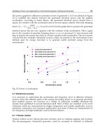
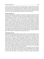
Fig. 3.15 Typical correlations of the absorption coefficient for metals (continuous curves)
and oxides (dashed curves): a) with temperature for pure and oxidized steel; b) with
temperature for the majority of refractory metals and oxides; c) with wavelength of
laser radiation incident on the heated material. (From Burakowski, T., et al. [11]. With
permission.)
– deposition of an absorbing coating which in most cases also fulfills
the role of an anti-reflection coating. This can be a paint coating in the
form of paints, varnishes and colloids, powder, paste, electrodeposit, chemi-
cal or any other coating which exhibits good absorption of radiation. Ab-
sorption coatings are most often produced from saline compositions (e.g.,
magnesium and zinc phosphates), metal oxides (e.g., zinc, titanium, silicon,
chromium, iron, aluminum), non-metals, sulfides, carbides (e.g., silicon and
molybdenum carbides), graphite, soot, blackening, etc. They increase the ab-
sorption rate of the surface by even up to 90% at lower temperatures and up
© 1999 by CRC Press LLC
to 50% in the higher temperature range (approx. 1500ºC). As an example,
paints of the gouache type increase absorption rates by 60 to 90% [25−27],
magnesium zinc Zn
3
(PO
4
)
2
or magnesium phosphate coatings Mn
3
(PO
4
)
2
up
to 55 to 90%, iron sulfide coatings (Fe
2
S
3
) up to 20 to 40%, graphite coatings
up to 40 to 70% [11, 23−27]. An interesting development is that of exothermic
oxide-metal coatings (e.g., FeO+Al, FeO+Si) which, besides raising the ab-
sorption rate of radiation, also cause the emission of heat. This is achieved by
a exothermic reaction between the components of the coating, initiated by
laser radiation. Such coatings may, within certain limits, intensify the effec-
tiveness of laser heating, conducive to a decrease of the power density of the
beam, thus to using lower power lasers. With appropriately selected compo-
sition, the coating may also prevent its constituents from migrating to the
substrate [24].
It is also possible to employ combinations of the above methods.
When selecting the method of enhancing the absorption rate of the
surface, one should take into consideration that increasing surface rough-
ness causes a deterioration its three-dimensional quality. It does not, how-
ever, cause changes of the chemical composition of the metal’s heated
zone which usually, although to a negligible degree, takes place in the
case of absorbing coatings. Unless remelting of the substrate material takes
place, such coatings either do not cause deterioration or cause only insig-
nificant deterioration of surface quality. Good absorbing coatings should,
moreover, feature good adhesion to the substrate, stability of thermophysical
properties, homogeneity of properties and of thickness, as well as ease of
deposition and stripping [24]. The thickness of such coatings usually does
not exceed 0.1 mm.
Since laser heating is usually carried out in air, a protective atmo-
sphere is introduced, usually nitrogen or argon at (0.5 to 1.0)∞10
5
Pa pres-
sure [5, 11]. This is done to protect against oxidation of the substrate which
was not preoxidized, if it is detrimental to the technological process, but
predominantly to protect the laser lenses against radiation.
3.4.3 Depth of penetration of photons into the metal
The initial phase of laser heating consists of absorption of photons which
are not reflected from the surface by free or bound electrons of the heated
material. Because of the high frequency of laser radiation, exceeding many
times the frequencies of electromagnetic radiation used for induction heat-
ing, the depth of penetration of photons into the heated material is small. It
can be determined from a formula analogous to that used for induction
heating [7]:
(3.4)
where: d - depth of penetration of laser radiation into the heated material,
m;
ρ
- resistivity (reciprocal of conductivity) of heated material, Ω°m;
µ
-
© 1999 by CRC Press LLC
relative magnetic permeability of heated material; f - frequency of changes of
electromagnetic field, bound to laser radiation wavelength by the correlation:
f = c/
λ
, where c - velocity of light (wavelength of 1 µm corresponds to a
frequency of 3.33∞10
-15
Hz).
According to equation (3.4), the radiation of molecular CO
2
lasers pe-
netrates the material deeper than that of Nd-YAG lasers.
To simplify the problem it can be said that photons from infrared radia-
tion penetrate materials that are not transparent to this range of frequencies
to a depth not exceeding 10
-6
to 10
-5
cm (1 to 10 µm), i.e., a depth which is
comparable to the wavelength of the incident radiation [6, 7].
Photons are absorbed by free or bound electrons of the heated material
and cause a rise of their energy. Electrons with higher energy interact with
the crystalline lattice and with other electrons and cause passing of energy
deeper into the heated material which is manifest by a rise of temperature.
From the zone heated by the penetrating photons the heat is therefore passed
on to the colder zones of the material by means of heat conduction at a rate
which depends on the conductivity coefficient of the given material which is
significantly higher for metals than for non-metals.
Usually materials with high thermal conductivity are characterized by
high electrical conductivity and, at the same time, high reflectivity. These
are properties which characterize metals. For non-metals there is a gener-
ally opposite rule. For this reason, the intensity of conducting heat into
the material from the directly heated surface of the metal is greater than
for an absorptive coating deposited on the metal substrate.
Assuming that the diameter of the laser spot is 20 mm and the depth
of photon penetration is approximately 10 µm, the volume of material af-
fected by photon penetration is approximately 3 mm
3
. In this volume there
occurs absorption of 0.5 to 10 kW of radiant power and its transformation
into heat energy. Such great powers evolved in such small volumes cause
almost instantaneous heating of that volume of material. The time of energy
transfer by electron collisions is approximately 10
-12
to 10
-14
s, while the time
of energy transfer to the crystalline lattice is approximately 10
-11
to 10
-12
s [6].
For normal and gigantic laser pulse durations of 10
-3
to 10
-7
s it is safe to
assume that during one pulse, electrons which absorbed photons collide
many times with other electrons and with the lattice. For this reason it can be
assumed that radiant energy is instantly transformed into heat energy at the
site where radiation is absorbed. Thus it is possible to obtain uncommonly
short heating times for laser heating, ranging from 10
-1
to 10
-8
s [4, 27, 29].
Transfer of heat from heated spots by penetration of photons (limited to a
layer of a fraction of a micrometer to several micrometers at the most) to the
remaining portion of the load is significantly slower and equal to the rate of
heat conduction by the given material.
In laser heating, the highest temperature is attained by the thin subsur-
face layer in the zone of incidence of the laser beam (i.e., in the laser spot);
in stricter terms, in the zone of the greatest power density. Surface tempera-
ture distribution approximately corresponds to the distribution of
© 1999 by CRC Press LLC
Fig. 3.16 Schematic representation of the interaction of laser radiation with material.
power density in the cross-section of the beam at the site of the laser spot
[30].
Heat accumulated in the surface layer heated by laser radiation (over
90% of the total heat evolved) is passed on concentrically into the mate-
rial by way of heat conduction. Thus, cooling rates are very high, com-
pared to rates of heating. Only a small portion of the heat delivered to the
material (max. 10%) is given off by radiation of the material’s surface
layer (Fig. 3.16).
The efficiency of laser heating is very low. This efficiency depends on
the type and design of the laser heater and on the absorption coefficient
of the heated surface. On the average, the efficiency of heating a solid by
laser pulses ranges from 2 to 3%, while that of continuously operating gas
lasers ranges from 5 to 7%.
3.4.4 Laser heating stages
For given values of exposure time t and absorbed power density q = q
0
A,
the heated material, e.g., steel, may be subjected to successive heating stages
to a higher temperature [11, 30] with a rise of q and t. Each such stage
includes the previous heating stage (Fig. 3.18).
Stage 0. Heating to temperature T
max
<A
1
(per iron-carbon phase diagram)
at which no phase transformations take place in solid steel. The heated zone
includes material at temperature T<T
max
, practically T<150°C.
Stage I. Heating to temperature T
max
<T
m
(where T
m
is melting point) at
which phase transformations occur in the solid state. Due to the rise of
surface temperature, emission of electrons and photons begins. The heated
© 1999 by CRC Press LLC
zone comprises the usable zone (at temperature A
1
<T<T
m
), i.e., that in which
the
α
∩
γ
transformation takes place; next - further away from the laser spot -
tempering, and a unusable zone, i.e., that which is at temperature T<A
1
ac-
cording to Stage 0. This is the typical zone for carrying out heat treatment.
Stage II. Heating to temperature T
max
⊕T
m
at which the steel melts. The
heated zone comprises: the usable zone, i.e., remelted (at temperature T⊕T
m
),
the zone of phase transformations (at temperature A
1
<T<T
m
), i.e., hardened
- after cooling down - and tempered (per Stage I), as well as the unusable
zone (per Stage 0). During heating the surface which constitutes the bound-
ary of melted material propagates inward, thereby increasing the zone of
melted material to the moment of breaking off of heating or equalizing the
amount of heat delivered with the amount of heat conducted to deeper,
unmelted layers.
Stage III. Heating to the temperature of vaporization T
max
>T
v
(where
T
v
is temperature of vaporization) at which steel undergoes rapid vapor-
ization and plasma is formed which impedes or even stops (screens) the
influx of radiation to the material by absorbing it. In such conditions it is
possible - besides hollowing, cutting or welding - to harden the material
by means of shock waves generated in that material due to sudden pulsed
impact of propagating plasma. The heated zone comprises the vaporized
zone (a crater) at temperature T⊕T
v
and the zone per Stage II.
Heating per Stage 0 is, from a technical standpoint, of no practical
significance and it will not be included in further considerations.
Fig. 3.17 Ty pical correlation between temperature and time of exposure in heating of
metal by pulsed laser radiation. (From Burakov, V.A., et al. [30]. With permission.)
Because of very high densities of absorbed power in laser heating, steel
temperature rises rapidly with time of exposure and after cutting off the
influx of radiation drops equally rapidly (Fig. 3.17), mainly due to heat
conduction into the material (so-called cooling by load mass) and par-
tially due to radiation of heat to the environment [30, 31].
Maximum heating rate may even exceed 10
6
K/s and occurs in the sur-
face layer of the heated material at the beginning of the heating pulse. It
© 1999 by CRC Press LLC
transformation in the solid state are shifted upward while rapid and uniform
solidification (big number of crystallization nuclei) allows non-epitaxial grain
growth. The structure is thus more refined.
Heating without remelting (per Stage I) is applied in cases of heat treat-
ment. Heating with remelting (per Stage II) is applied for welding, cutting,
heat treatment as well as for alloying and surface plating. Heating with
vaporization (per Stage III) has found application in perforation and
cutting operations but could also be utilized for detonation hardening of
crater walls by the shockwave formed as the result of rapid vaporization.
Detonation hardening has not, however been practically utilized to date
(Fig. 3.19).
3.4.5 Temperature distribution in laser-heated material
The effectiveness of laser heating depends on the heat balance of absorbed
power within the thin subsurface layer of cold material and power given
off to the environment by way of radiation of the heated surface. For
simplicity, the latter value maybe neglected.
If the rate of radiant power input (or power density q
1
) is high relative
to the power of heat conducted into the material, the surface temperature
T
1
is high and localized within the thin subsurface layer. If the input
power density q
2
is lower, i.e., if the rate of power input is less and compa-
rable to the rate of heat loss by conduction into the material, surface
temperature T
2
is lower and reaches deeper layers of the material (Fig.
3.20). temperatures T
1
and T
2
rise with further input of radiant power,
similarly to the depth of thermal penetration, until stabilization is reached.
Fig. 3.20 Dependence of temperature profile on absorbed power density.
At the moment when radiant power input from the laser is interrupted
(e.g., expiration of the laser pulse or displacement of laser beam to an-
other zone) there occurs cooling of heated sites, including cooling by con-
duction to deeper-lying material bulk. In most cases, the cold bulk of the
material may be treated as semi-infinite which rapidly consumes thermal
power input. In such cases load mass cooling or autocooling occurs. When
© 1999 by CRC Press LLC
heating thin elements with low mass (as in e.g., knife edges, edges of
circular saw teeth, thin sheet, etc.) which do not ensure rapid autocooling
required for local hardening of an element, additional spray cooling is
applied [33].
It appears from the above that the degree of heating and character of
temperature distribution depend on physical properties, or, more strictly,
on thermophysical properties of the heated material and on the shape and
value of absorbed power distribution.
The distribution of temperature in laser-heated materials, especially in
metals and predominantly in steels, has been the topic of theoretical and
experimental determination by many researchers [33−46].
In the case of a fixed beam (one that is not displaced relative to mate-
rial) the distribution of temperature in the heated material may be deter-
mined from heat conduction equations for point, linear or area heating.
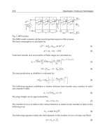
For a Gaussian distribution of power density the following correlation
holds true [33, 34]:
(3.5)
where: T(r,z,
τ
) - temperature at radius r and depth z from the focal point
of heating after time
τ
; P
abs
- power of absorbed radiation;
τ
f
- time neces-
sary for flow of heat through distance r
f
(
τ
f
= r
2
f
/4a); r
f
- distance from
beam axis at which power density decreases to 1/e
2
of value of maximum
power in beam axis; z - perpendicular coordinate to surface of heated
material in direction of heat propagation (into the material); r - radial coordi-
nate, perpendicular to coordinate z; c - specific heat of material; r - material
density; a - coefficient of thermal conductivity of material.
In laser heating practice the case of heating with a fixed beam occurs
only very seldom. Usually the laser beam or the treated material is displaced
relative to each other with a given velocity u. This case may be described by
the equation of temperature distribution in the feed (scanning) plane of the
beam along axis x, which holds true for the Gaussian distribution of power
density in the beam [33]:
(3.6)
where:
υ
- beam feed rate;
λ
- thermal conductivity; z
0
- depth to which
heat penetrates into the material during the action of the laser beam
τ
= r
f
/
υ
; x - coordinate perpendicular to coordinate z, in agreement with
the direction of beam displacement; T
0
- temperature of environment.
© 1999 by CRC Press LLC
For short times of beam action (
τ
<<
τ
f
) which take place when the values
of u are high and the diameter of the laser spot is small, the value of z
0
equals
[33]:
(3.7)
while the maximum temperature in the heating cycle is equal to:
(3.8)
For longer times of laser beam action (
τ
>>
τ
f
) which take place when the
values of u are low and the diameter of the laser spot is big, the following
correlations apply [33]:
(3.9)
(3.10)
The correlation (3.10) holds true only to the point at which the surface
temperature T
max
attains a value equal to that of melting temperature T
m
.
Fig. 3.21 shows the temperature field for the case of the point source,
across the surface of a semi-infinite body, while Fig. 3.22 shows the same
for the case of a very strong and rapidly moving point source [29].
For many practical cases, the most interesting parameter to know is
maximum temperature and its distribution along the depth axis z (i.e., along
the axis of the laser beam).
For the case of pulse heating with phase transformations without
remelting, by a beam with spot diameter d, incident perpendicular to the
surface of the treated material, the temperature T
z
at any point along z
(to 0 ≤ z ≤ z
h
, where z
h
is depth at which the allotropic transformation
Fe
α
∩ Fe
γ
takes place) is described by the following formula [14, 30, 31]:
(3.11)
where: a - coefficient of temperature conductivity of heated steel, cm
2
/s;
λ
- coefficient of thermal conductivity of heated steel, J/(s∞cm∞K).
© 1999 by CRC Press LLC
Fig. 3.23 Effect of duration of laser pulse t on temperature distribution T
z
along axis
perpendicular to heated surface (for M2 high speed steel). (From Burakov, V.A., et al.
[30,31]. With permission.)
Fig. 3.23 shows the correlation T
z
= f(z) for different values of t, with the
isotherm T
h
for M2 grade high speed steel indicated (T
m
= 1310°C) [30, 31].
The case of pulse heating with remelting and phase transformations
is more complicated by the fact that calculations must take into consider-
ation additional energy losses for latent heat of melting Q
m
of the heated
material.
Based on report [46], as well as on certain simplifying assumptions and
indirect calculations, it is possible to determine the temperature of the surface
and the depth of remelted zone z
m
by the following equations:
(3.14)
(3.15)
where: c - specific heat, J/(g°K).
For surface temperature T
max
= T
v
(where T
v
- temperature of vaporiza-
tion, T
v
∪ 2900ϒC) the depth of remelting is denoted by z
mE
.
The total depth of the hardened layer z
ht
is equal to the depth of re-
melting z
m
and the depth of hardening z
h
(determined from formula (3.15)
for T
max
= T
m
and for that value, denoted by z
hL
).
z
ht
= z
t
+ z
hL
(3.16)
© 1999 by CRC Press LLC
On the basis of experimental results or formulas quoted in literature [33 −
46], it is possible to construct plots which correlate the values of z, T, q and
τ
for any chosen material with known thermophysical properties. Such plots
are developed by research centers and manufacturers of technological lasers.
The method of construction of such plots for steel, based on equations
(3.11 to 3.16) and known values of
λ
and Q
m
, is given below [30, 31].
Thermophysical properties of steel change with temperature during
heating, in a way similar to that of the absorption coefficient A (an almost
leap change of value occurs at the transition of the metal from solid to
liquid). For this reason, calculations should take into account either
tabularized, temperature-dependent values, or determine them experimen-
tally for given temperature intervals. It is also possible to assume average
constant values, keeping, however, in mind that the results of such calcula-
tions are only approximate. The temperatures T
h
and T
m
are read from the
steel phase diagrams.
The plot is constructed in the following way [30, 31]: upon appropriat-
ing values of surface temperature T
max
(within the range of A
3
≤T
max
≤T
m
) and
time of exposure
τ
(e.g., within the range of 1 to 10 ms), the value of ab-
sorbed power density q necessary to achieve the assumed T
max
temperatures
is determined from the formula (3.12). Next, assuming a given value of the
absorption coefficient A, the correlation q = q
0
A is used to determine the
input power density q
0
, i.e., the power density of the beam as it exits the
laser.
Next, for the same values of T
max
and
τ
, the formula (3.13) is used to
determine the value of the depth of hardened layer z
h
, placing T
h
= 912ϒC, per
the iron-carbon phase diagram.
Using equations (3.14) and (3.15) for heating with remelting, and taking
the value T
m
= 1310ϒC from the iron-carbon phase diagram and T
m
within the
range: T
m
< T
max
< T
e
, an analogous method is pursued.
With mutual correlations between z, T, q and
τ
determined, the dia-
gram is plotted. Fig. 3.24 shows such a plot for M2 grade high speed steel.
The correctness of the assumed methodology has been tested in practice
by a measurement of the depth of zones z
h
and z
m
for different conditions
of laser treatment on metallographic mounts [30, 31].
The accuracy of the approximate formulas given above has been estimated
for pulse heating of tool steels [42, 43] and for carbon steels [41] as ±5 to 10%
in the case of heating to temperature T
m
. Treatment with remelting of the
surface lowers the accuracy of calculations. When heating a surface to above
2000ϒC, the experimental data differ from calculations by as much as ±20%.
More accurate determination of the real situation in the high temperature
zone of the diagram is possible after e.g., taking into account changes in
absorption with the rise of surface temperature T
max
. In this case the probabil-
ity of an error may be lowered to ±10 to 15% both for carbon steels [43] and
for tool steels [30, 31].
By using such plots, given in literature for continuous and pulse laser
treatment, it is possible to control the conditions of heating of the surface
© 1999 by CRC Press LLC
Fig. 3.25 Focusing of beams and heating the load: a) diagram of focusing of laser
beam with Gaussian power density distribution (e.g. for laser beam of diameter D ∪11
mm, emitted by molecular CO
2
laser of wavelength
λ
= 10.6 µm and focal length f =
50 mm, the diameter of the laser spot d ∪50 mm; b) single mode defocused laser beam
- load surface behind focal constriction, single path heating; c) single mode continu-
ous defocused beam - load surface before focal constriction, multi-path heating, heated
layers overlap, causing possibility of tempering of prior hardened layer; d) single mode
beam, oscillating in one plane, multi-path heating; e) multi-mode continuous beam; I
- schematic of focusing or oscillation; II - schematic of heating and displacement of
load; III - cross-section of hardened layers, approximately corresponding to power
density distribution in beam.
Laser heating of a surface of the treated material may be carried out in
a manner similar to that with the electron beam. However, due to the
specifics of the laser beam, the most often used type of heating is sequen-
tial or point-insular with beam deflection or beam transverse movement
across precision x-y stages, rotation and movement of the load or a com-
bination of the above. The input power density on which thermal pro-
cesses taking place at the surface depend are controlled by focusing and
defocusing of the beam (Fig. 3.25) and by a change of exposure to radia-
© 1999 by CRC Press LLC
tion time. Depth of heated or remelted layer for a given power density de-
pends mainly on exposure time and fluctuates within the range from several
micrometers to several millimeters. In most common cases it is of the order of
several tens of micrometers [14, 19, 22, 30−36].
As opposed to stock-removing treatments (cutting, hollowing, perforat-
ing), forming (blanking, inscribing, bending) or joining (welding), in metal
surface engineering the one-mode Gaussian power density distribution in
the beam is not desired. What is desired is a multi-mode distribution, as far
as possible close to uniform.
Fig. 3.26 Diagrams showing different power density distributions in load: a) single
mode distribution, obtained by condensing lens and non-oscillating mirror; b) distri-
bution close to rectangular, obtained by mirror oscillating in two perpendicular di-
rections; c) rectangular distribution obtained by condensing several radiation beams;
1 - laser beam; 2 - shape of power density distribution; 3 - treated object. (From
Burakowski, T., et al. [11]. With permission.)
Usually, the spatial distribution of power density in high power con-
tinuous and pulse laser beams is irregular and for very high power lasers,
this irregularity is even greater. This distribution may be smoothed out by
the application, outside of the laser, of a set of lenses or apertures, colli-
mating of laser beams, or oscillation scanning by the beam (with the aid
of a vibrating mirror). Focusing also smoothes out the distribution of power
density in the beam. Usually, however, it is not possible to achieve a fixed
power density distribution throughout the cross-section of the laser beam.
In the outer zones of the beam, power density is usually lower than in the
remaining zone. Two methods of obtaining a uniform distribution of power
density are shown in Fig. 3.26 [11]. Most often, the beams are circular in
cross-section, with a diameter of over 30 mm; in rarer cases rectangular, with
dimensions of several tens of millimeters per side.
Scan patterns obtained with the aid of a laser beam are similar, as in
the case of an electron beam. In general, laser beams are less flexible than
electron beams.
© 1999 by CRC Press LLC
3.5 Laser techniques
The utilization of laser radiation in surface engineering depends on a great
many factors, of which the most important are different properties of materi-
als subjected to laser treatment, as well as different properties of the laser
beam (Fig. 3.27). Combinations of different properties of material and beam
allow the utilization of Laser Beam Machining [36] in approx. 200 different
areas [32]. Of these, surface engineering utilizes only some - up to 20%. They
differ among one another - like in electron beam heating - mainly by combi-
nations of power densities delivered to the load (and especially of absorbed
power q) and sometimes by combinations of interaction of the beam t with the
treated material. Approximate values of these parameters, typical of different
technological groups, are shown graphically in Fig. 3.28 and given in Table
3.1. All these methods are carried out in order to enhance the service life of
machines, mainly with the utilization of CO
2
and Nd-YAG lasers [47-75].
Lately, increased application of excimer lasers for forming of surface layer
properties is noted [76].
Fig. 3.27 Graphic portrayal of factors affecting the results of laser treatment. (From
Kusiñski, J. [33]. With permission.)
foaming
of laser-treated material
© 1999 by CRC Press LLC
Tests of laser annealing carried out on layers of arsenic, silicon, chro-
mium, aluminum, graphite, etc. on different substrates have shown that their
properties very strongly depend on annealing parameters and on the initial
condition. Laser annealing is applied for correcting the resistivity of metal
and metal-ceramic resistors (e.g., Cs-SiO
2
, Au-Cr
2
O
3
), for forming of ohm con-
tacts in semiconductor instruments and for the formation of current paths
[29].
A significant utilization of laser annealing, especially in the area of
machine building, is local lowering of hardness and increase of ductility
in order to facilitate subsequent deformation of those sites or to increase
fatigue strength. Rapid heating of cold-formed steels causes shifting of
beginning and end of primary crystallization to the high temperature zone
and this, in turn, causes a rise in the number of crystallization nuclei and
significant refinement of grains in comparison with slow heating. The
greatest impact of heating rate on grain size is observed when the coeffi-
cient of deformation is low, close to the critical value [29].
In order to lower hardness and to increase ductility of metals, besides re-
crystallization annealing laser annealing with phase transcrystallization is used.
This can also be utilized in the heat treatment of thin strip, sheet and wire [29].
Tempering. This process is used after hardening of steel and consists of
heating it to a temperature lower than eutectoid and subsequent cooling
in order to enhance ductility and to reduce brittleness at the cost of a
drop in hardness. During rapid tempering by laser, steel undergoes the
same phase and structural transformations as during slow conventional
tempering (in a furnace). The formation of tempered martensite, decom-
position of retained austenite and the formation of a mixture of ferrite
and cementite all take place but the temperatures of all these transforma-
tions are shifted upward, especially the temperature of decomposition of re-
tained austenite.
The short time of action of the laser beam yields very fine carbides and a
significantly higher hardness than that obtained by conventional tempering.
Moreover, it results in higher static and impact strength, higher cold brittle-
ness and temper brittleness. Laser tempering of carbon steels allows the ob-
taining of mechanical properties comparable to those of conventionally tem-
pered steel with chromium and vanadium alloy additives. The structure and
properties of laser tempered steel may be controlled by a change of energy
parameters (power density, exposure time) and by retempering, employing
different parameters.
Laser tempering is used in those cases where there is a need to locally
increase the ductility of or impact strength at e.g., join sites of different com-
ponents after prior induction hardening. Laser tempering is also used on
tools which were hardened and tempered at a low temperature [29].
Laser tempering allows a change in the distribution and lowering of
the value of quenching stresses formed as the result of intensive local
hardening, e.g., by laser, electron beam or plasma, especially in cases of re-
melting where a high stress concentration is formed [78].
© 1999 by CRC Press LLC
No significant structural differences are noted when comparing laser tem-
pering with conventional tempering of carbon and alloy steels [81, 82]. The
recommended practice is to apply high temperature laser tempering for com-
ponents working under dynamic loads at low temperatures when it is impor-
tant for the material to avoid stress concentrations, formed e.g., during laser
hardening [82]. The laser beam may also be utilized for annealing and tem-
pering of welds and padwelds [83].
Preheating. The laser beam may also be used to increase the ductility
of different materials by preheating the surface immediately before the
next surface treatment or forming operation, e.g., before machining of ma-
terials which are difficult to machine (sintered carbides, creep-resistant
steels and alloys, hardened alloys) [2]. Other applications include pre-
heating prior to forging, also in order to achieve fine-grained structure
[29], before welding [50], prior to laser treatment, e.g., plating or harden-
ing, in order to avoid cracks [51] or prior to laser hardening in order to
aid the heating process when using a high powered laser, by preheating
up to 200ϒC [84]. Very advantageous is multiple laser heating in order to
facilitate bending of even thick metals [14]. By laser heating a material to
a temperature close to the melting point directly prior to subjecting it to a
cutting tool or a welding torch, hardness and cutting resistance are re-
duced, bringing about a reduction in the deformation of components be-
ing treated or joined, an extension of the life of the cutting tool and short-
ening of treatment time [2, 8].
3.5.1.2 Remelt-free hardening
Remelt-free hardening consists of heating a metallic material to a tem-
perature at which a known phase transformation takes place (e.g., for steel to
several K above A
c3
) and self-cooling, resulting in a structure which is less
stable than the initial one and usually harder. In the case of steel, this struc-
ture is usually martensitic.
Hardening parameters are selected in such a way as to allow the oc-
currence of the phase transformation (in steels - the martensitic transfor-
mation) without the occurrence of remelting, even remelting of a thin
surface layer. Remelting is usually accompanied (after self-cooling) by the
obtaining of a less hard surface of the layer than that obtained without
remelting. This loss in hardness may even reach 20 to 30%. If remelting oc-
curs, retained austenite appears in the remelted and resolidified structure of
high alloy tool steels. This retained austenite is difficult to remove even by
cryogenic treatment [50]. Usually, for remelting-free hardening the applied
power density is 10
2
to 2°10
4
kW/cm
2
and the time of exposure is 10
-2
1 s. The
typical heating rate is approximately 10
6
K/s and cooling rate is approxi-
mately 10
4
K/s [11].
In remelting-free laser hardening phase transformations do not, how-
ever, occur at the same temperatures as in conventional hardening, in
accordance with phase diagrams for the particular elements forming the
given alloy. Due to the very big heating and cooling rates, exceeding conven-
© 1999 by CRC Press LLC
tional rates by several orders of magnitude, phase transformations at
temperatures which are appropriate for conventional hardening “lag be-
hind.” Such phase transformations require temperatures higher by sev-
eral tens K [85].
In comparison with normally employed methods of conventional sur-
face hardening (induction, flame or plasma), laser hardening yields harder
surface layers with a more refined grain structure and thinner (thick-
nesses usually within 0.25 to 2.5 mm). Obtaining of thicker layers requires a
longer exposure time, of the order of even whole seconds. The thickness of
the hardened layer is usually 0.25 to 0.75 mm for steel, approximately 0.5 mm
for gray cast iron and approximately 1.0 mm for nodular cast iron [11].
Similarly to the case of remelt-free hardening by laser beam (see Fig.
2.24) laser hardening can also be applied as a single layer and multi-layer
version, as well as simple or complex.
Fig. 3.29 Different hardness distribution in continuous laser-hardened (with different
hardening parameters) superficial layer on carbon steel.
Simple remelt-free hardening consists of laser hardening of a material,
the initial state of which is the result of a previous forming, surface or
machining operation. On account of cooling rates which are much faster
than in conventional hardening, it is possible to harden steels and alloys
which are non-pardonable by conventional means, e.g., steel with a carbon
content of 0.2% [50, 51]. Fig. 3.29 shows hardness profiles on low carbon
steels. As a general rule, an increase in carbon content causes a rise in
hardness [91, 92] and thickness of the hardened layer for the same laser
treatment parameters. This is mainly the result of a rise in hardenability
and of the lowering of austenitizing temperature [50, 51]. For steels which
are normally hardenable by conventional means, hardnesses obtained by
laser treatment are approximately 30% higher than those obtained by con-
ventional hardening. This is connected, among other factors, with a more
© 1999 by CRC Press LLC
refined microstructure (carbides do not have the time required to dissolve
during austenitization). Increments in hardness are accompanied by ap-
propriate increments of yield strength, ultimate tensile strength and wear
resistance [50, 51].
Good results are also attained in hardening of gray cast iron, with a
mainly pearlitic matrix. This enhancement is most pronounced in the rise
of tribological properties, with relatively small layer thicknesses [50, 51, 86,
89, 90].
The residual stresses formed (both thermal and structural) depend on
the energy and geometry conditions of laser radiation. Along hardened
beam paths, compressive stresses almost always prevail, while between
paths, tensile stresses dominate [93, 123]. In martensitic stainless steels,
compressive stresses prevail near the path surface while tensile stresses
are present near the core [233]. A decrease of distance between two paths
down to their touching each other and partial overlap is conducive to the
formation of a complex distribution of residual stresses, due to local tem-
pering of already hardened zones [93-96].
As a general rule, fatigue strength rises. The mechanism of fatigue dam-
age occurring in contact fatigue testing is significantly different from that
of classical pitting which occurs in linear or point contact of mating sur-
faces. Fatigue damage is initiated by microcracks in the hardened path
and, subsequently, flaking off of layer fragments situated between the
microcrack network. In the exposed matrix there appear secondary cracks
which, by developing, lead to classical pitting [97]. Upon bending, fatigue
cracks are temporarily arrested at the boundaries between the hardened
paths and the core and their value changes by a leap. Within the paths,
the rate of cracking is not big, while in the tempered zones it is even lower
[98−101].
Complex remelt-free hardening consists of laser hardening as shown
in Fig. 2.24, which also holds true for electron beam hardening. Thus it can
be carried out after conventional heat treatment, e.g., hardening, tempering,
annealing, or surface diffusion treatment, e.g., carburizing, nitriding, or
after mechanical strengthening operations. Besides, in addition to what is
shown in Fig. 2.24, this operation can be carried out after the deposition of
coatings by different methods (e.g., electro-vibration, concealed arc [102],
thermal spray or by PVD). It is also possible to apply some of these treat-
ments after laser hardening or to apply them simultaneously. As an ex-
ample, simultaneous arc and laser heating of normalized 1045 steel allows
obtaining 2.5 to 3 times greater thickness of the hardened layer and a high
hardness of 56 to 62 HRC in comparison with results obtained by laser
heating alone [103].
In laser hardening of steel martensitic transformation occurs. Depending,
however, on energy and geometric parameters of the laser beam, the proper-
ties of the steel and the type of prior (pre-laser) treatment, different martensi-
tic structures, as well as different proportions of other residual phases (car-
bides, ferrite, etc.) are obtained.
© 1999 by CRC Press LLC
Fig. 3.30 Hardness distribution in direction perpendicular to center of laser path: a)
1045 steel, normalized (1) and hardened and tempered (2) without laser hardening
and with transformation hardening (correspondingly: 1’ and 2’); b) 52100 steel, an-
nealed (3) or hardened and tempered (4) without laser hardening and with transfor-
mation hardening (correspondingly 3’ and 4’). (From Zenker, R., et al. [104]. With
permission.)
In hypoeutectoid steels, e.g. 6150H: 0.47%C; 0.26%Si; 0.64%Mn; 0.003%P;
0.018%S; 0.98%Cr; 0.09%V, normalization, carried out with high beam
power density, causes lath martensite in big, regular clusters, to form in
the subsurface zone, in a way similar to that occurring during conven-
tional hardening. In deeper zones, increasingly finer, irregular martensite
is found. It is so fine that it may be impossible to see with the resolution of
an optical microscope. Often, traces of pearlite may be observed in the
microstructure. The greater the pearlitic zones in the initial condition of
the material, the more often such traces occur in the final microstructure.
The presence of pearlite is an indication that the temperature at that
particular site did not exceed A
c3
[88, 104].
In hypoeutectoid steels, e.g., the 90Cr3* grade, after softening annealing
with comparable energy and geometrical parameters of the laser beam, lath
martensite and residual austenite occur in the subsurface zone. In the transi-
tion zone the predominant component phase is very fine acicular or lath
martensite, as well as numerous undissolved carbides [104].
Adhering directly to the laser hardened zone in steel or to a conven-
tionally hardened and tempered zone which was additionally laser hard-
ened is a more or less broad zone of tempered material with a hardness
© 1999 by CRC Press LLC
Fig. 3.31 Products of martensitic transformation and hardness distributions of hypo- and hypereutectoid steels, laser transformation
remelt-free hardened, after different prior heat treatment: a) zone of action of laser beam on object surface; b) hardness profile. (From Zenker,
R., et al. [104]. With permission.)
© 1999 by CRC Press LLC
significantly lowered relative to that of hardened sites. The effect of temper-
ing is manifest especially in steels with low temper resistance, e.g. in 52100
grade steel, and is characterized by a low increase of hardness (relative to
initial) [104].
In steel which was laser hardened with prior hardening and temper-
ing, hardness distribution is uniform, while in steel that was laser hard-
ened after prior normalizing, hardness fluctuates more than in conditions
of other initial heat treatment. It first increases from the surface in the
direction of the core and then drops off to the level of core hardness
(Fig. 3.30). A lowering of hardness at the surface of 52100 steel is probably
due to the big proportion of retained austenite in this zone [104].
Fig. 3.31 shows the products of martensitic transformation and hard-
ening profiles obtained during remelt-free laser hardening of hypo- and
hypereutectoid steels, subjected to different prior heat treatments [104].
Fig. 3.32 Hardness profiles of superficial layers following annealing of laser hardened
Russian steels: a) plain carbon; b) alloyed; c) eutectoid; 1 - U8
*
; 2 - U10
*
; 3 - U12
*
; 4 -
C1045; 5 - 60S2
*
; 6 - HWSG
*
; 7 - 9HS
*
; 8 - HWG
*
; 9 - 12H1
*
; 10 - H
*
; 11 - H12M
*
; 12 -
C1062; 13 - 7H3
*
. (From Kremnev, L.S., et al. [105]. With permission.)
© 1999 by CRC Press LLC
If the condition of not remelting of the surface layer is kept, lowering of
power density of the laser beam and shortening of the time of its action is
not conducive to qualitatively different processes but only to a displacement
of the said zones in the direction of the material surface. With the same
radiation parameters, the depth of hardening rises with a rise of thermal
conductivity of the treated material. The hardness of laser hardened steels
drops with a rise in the content of retained austenite. Fig. 3.32 shows some
Fig. 3.33 Hardness distribution of low alloy steels containing titanium (initial condi-
tion: hardened and tempered), hardened by CO
2
continuous laser beam with fixed
power density of 5.88 kW/cm
2
: a) steel containing 0.9% Ti, only laser hardened with
different exposure times; b) steel containing 0.9% Ti, laser hardened with different
exposure times and subsequently glow discharge nitrided 60 h at 520ϒC; c) steel
containing 0.21% Ti and 0.9% Ti, only glow discharge nitrided (60 h at 520ϒC), laser
hardened (exposure time: 2.5 s) and laser hardened (exposure time: 2.5 s) followed by
glow discharge nitriding (60 h at 520ϒC).
© 1999 by CRC Press LLC
hardness profiles for different steels: carbon (characterized by high thermal
conductivity), alloy (with thermal conductivity, on an average half that of
carbon steels) and eutectoid (with lowest amount of retained austenite). If
maximum thickness of the hardened layer using same laser heating param-
eters is the desired goal, it is recommended to use eutectoid steel, alloyed by
elements which raise thermal conductivity, and to subject it to prior heat treat-
ment which yields a troostite structure [105].
A change in the hardness profile and a change of the content of the
element alloying the surface layer by diffusion may be obtained by utiliz-
ing a combination of prior thermo-chemical treatment and laser harden-
ing [132]. Fig. 3.33 shows the distribution of hardness on alloy steels con-
taining titanium: laser hardened only and laser hardened, followed by
glow discharge nitrided [11]. Such a combination enhances the steel’s
nitridability, resulting in thicker and harder nitrided layers [132]. Fig. 3.34
shows a diagram of correlations at different sites of the laser path be-
tween microstructure, nitrogen content and hardness at different distances
from the surface [106−110].
Fig. 3.34 Graphic representation of co-dependence between microstructure in the
laser hardened zone, nitrogen content and hardness distribution in normalized and
laser hardened 6150H steel, gas carbonitrided (4-8 h, 843 K). (From Zenker, R., and
Zenker, U. [109]. With permission.)
© 1999 by CRC Press LLC
Generally, remelt-free laser hardening increases the following: hard-
ness (to a degree higher than that obtainable by conventional methods),
static and fatigue strength, as the result of formation of favorable com-
pressive stresses [113], impact strength and ductility, corrosion resistance
and wear resistance [111, 118, 131]. As an example, wear of 1045 grade
steel is 10% less after laser hardening than after conventional hardening
[112]. Surface roughness after laser treatment does not change relative to
pre-treatment condition.
Remelt-free laser hardening is applied to harden cold work tool steels
[139, 142], high speed steels [127, 139, 148], structural steels, including
those containing chromium [96] and manganese [134]; low carbon steels
[87, 117, 128, 140] containing less than 0.2%C, medium carbon steels [147],
alloy steels, steels used for armor plates, corrosion resistant steels [122],
bearing steels, cast iron (especially gray) and for copper alloys [129].
3.5.1.3 Surface cleaning
Laser radiation, with shallow penetration into solids while heating them,
also causes a cleaning of the surface by desorption of vapors, gases and
contaminants adsorbed by that surface. The effect is enhanced by the em-
ployment of vacuum as the protective atmosphere and by using pulse
heating. When the pulses are very short, the gaseous contaminants and
atoms of foreign inclusions do not have the time needed to diffuse into the
surface. On the other hand, combined action of temperature and vacuum
cleans the surface quickly and effectively. Laser cleaning of materials in
vacuum is used in electronics to remove inclusions and adsorbed atoms of
oxygen, nitrogen, hydrogen, etc. from crystals of silicon, nickel, etc. It is
possible to obtain a surface of atomic purity in times substantially shorter
than those used in traditional cleaning methods [29].
In combination with the formation of slits, it is possible, with the aid of
a laser beam, to remove varnish coatings and to subsequently etch the
surface in etching solutions. The utilization of the difference in expansion
coefficients of coating and substrate material allows the use of the laser
beam in such a way as to cause so-called thermo-peeling of the coating,
due to the generation of substantial shear stresses at the interface [29].
3.5.2 Remelting techniques
3.5.2.1 Surface remelting
Surface remelting is a name given to a group of methods carried out with
the application of greater power densities and heating rates, consisting of
rapid remelting of a thin surface layer of the substrate material or of the
coating deposited on it, followed by equally rapid crystallization or
amorphization (Fig. 3.35). It is sometimes called pure remelting. Remelt-
ing always causes a change of surface roughness. In the laser - affected zone
a cloud of gaseous plasma is always formed.
© 1999 by CRC Press LLC