Volume 10 - Materials Characterization Part 9 ppsx
Bạn đang xem bản rút gọn của tài liệu. Xem và tải ngay bản đầy đủ của tài liệu tại đây (1.64 MB, 90 trang )
Richard L. Harlow, E.I. DuPont de Nemours
o
Richard L. Harlow, E.I. DuPont de Nemours
Richard L. Harlow, E.I. DuPont de Nemours
o
o
o
o
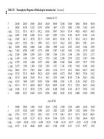
Table 2 Fractional coordinates x, y, and z (× 10,000) and isotropic thermal parameters B
iso
for Cu
6
Mo
5
O
18
x y z ORTEP illustration of the basic structural unit of Cu
6
Mo
5
O
18
. Each atom is represented by an oval, a
two-
dimensional projection of its ellipsoidal thermal motion. The unique atoms have been labeled, and some of
the symmetry-
equivalent atoms have been added (as indicated by the small letters at the end of the label) to
complete the coordination sphere around each atom. Source: Ref 14
Copper tetrahedra and molybdenum octahedra as packed into the unit cell. All the symmetry-
equivalent units are included. Source: Ref 14
−
+
−
−
Bond distances in angstroms and angles of the
−
anion in the green (a) and yellow (b)
modifications. T
he estimated standard deviations are given as single digits in parentheses after bond
parameters. A prime is added to the labels of the symmetry-
equivalent atoms. In the green form, the copper
atom sits on a center of symmetry (indicated by solid circle);
in the yellow form, a twofold axis passes through
the copper atom (indicated by solid oval). Source: Ref 15
−
Table 3 Positional and thermal parameters for Rb
2
[Pt(CN)
4
](FHF)
0.40
x y z
β β β β β
Perspective view of the unit cell of Rb
2
[Pt(CN)
4
](FHF)
0.4
. The small circles ar
e the partially filled fluorine
atom positions. The platinum-platinum spacing is the shortest known for any
−
1-
D metal complex. The
corresponding platinum-chain conductivity is the highest (~2000 Ω
-1
cm
-1
at 298 K) for any known complex of
this type. Source: Ref 16
Stacking of square-planar [Pt(CN)
4
]
x-
groups showing the overlapping of platinum d orbitals.
Source:
Ref 16
−
Richard L. Harlow, E.I. DuPont de Nemours
•
•
•
•
Richard L. Harlow, E.I. DuPont de Nemours
Richard L. Harlow, E.I. DuPont de Nemours
Brent L. Adams, Department of Mechanical Engineering, Brigham Young University
General Uses
•
Examples of Applications
•
Samples
•
•
•
•
Limitations
•
•
Estimated Analysis Time
•
•
Capabilities of Related Techniques
•
•
Brent L. Adams, Department of Mechanical Engineering, Brigham Young University
Brent L. Adams, Department of Mechanical Engineering, Brigham Young University
Construction of the stereographic projection. A point P
on the surface of the reference sphere is
projected to point P' on the projection plane
Crystal axes using the stereographic projection.
Spherical polar angles defining directions in the RD-TD-ND coordinate system.
Three consecutive Euler rotations defining an orientation.
The complete set of angles for Roe's analysis of orientation. The index i denotes
different pole figures.
The angles and fix the diffracting plane normal, r
i
, to specimen axes x, y, and z. The angles
i
and
i
fix
this direction to the crystal axes X, Y, and Z. Also shown are the Euler angles , θ, and .
Eulerian cradle mounted on the -axis of a diffractometer. The unit vectors S
0
and S depict the source
and diffracted beams, respectively. The angles χ and η correspond to those shown in Fig. 2.
≤ ≤ ≤ ≤
Expected pole orientations of preferred orientations in Cu-3Zn. (a) Expected
positions of <111> poles for
three specific variants of the preferred orientations. (b) Expected <111> orientations when two mirror planes
are introduced. Figure 8
shows the measured <111> pole figure for the same alloy; note similarities between
Fig. 7(b) and 8.
Measured (111) pole figure for Cu-3Zn. Source: Ref 2
Euler space in Roe's notation. Points in the cube represent discrete orientations. For materials of cubic
symmetry, regions I, II, and III represent equivalent orientations.
Orientation distribution function for copper 10100 tubing using method of Euler plots. and
vary as
shown in lower right-hand corner. The value of for each slice is given in each rectangle.
Brent L. Adams, Department of Mechanical Engineering, Brigham Young University
≤ ≤ ≤ ≤
(111) pole figure for copper 10100 tubing taken from the midwall.