Volume 18 - Friction, Lubrication, and Wear Technology Part 14 potx
Bạn đang xem bản rút gọn của tài liệu. Xem và tải ngay bản đầy đủ của tài liệu tại đây (1.81 MB, 80 trang )
Fig. 22 Bushing insert for pivoted-pad hydrostatic journal bearing. Source: Ref 21
Three-Sector Journal Bearing
This journal bearing, with three equally spaced axial grooves, has shown some degree of stability against self-excited
whirl. Castelli and Pirvics (Ref 26) have presented comprehensive numerically computed performance characteristics for
three- and four-axial grooved gas-lubricated journal bearings. Angular extent of each groove is considered to be 5°. Thus
for a three-sector bearing, the arc length of a sector would be 120 - 5 = 115°.
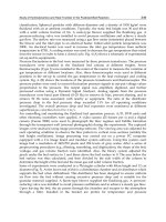
Figure 23 lists results in terms of the dimensionless load capacity parameter W' = W/p
a
rl plotted against the bearing
compressibility number . Note that the value of used here is actually the same as in Eq 1. The applied load is directed
toward the center of one sector. Evaluating W' and will determine the eccentricity ratio and thus the minimum film
thickness.
Fig. 23 Load function W' versus for three-groove journal bearing. Source: Ref 26
Information on many other sizes, load directions, and attitude angles can be found in Ref 26 and 27.
Helical-Grooved Journal Bearings
The helical grooving in this type of journal bearing enhances stability by reducing the attitude angle below that obtained
from a plain cylindrical journal bearing. These bearings are known for their stability and are often used as a possible
substitute for tilting-pad journal bearings.
Castelli and Vohr (Ref 28) solved the appropriate equations numerically for load capacity and attitude angle for the case
of l/d = 1.0, with various values of . Figure 24 lists the geometric parameters for the spiral-grooved bearing as used in
Ref 28. Figure 25 lists the results showing the load parameter W' = Wp
a
as a function of with the eccentricity ratio as
the third variable. Malanoski (Ref 29) shows good comparison between the theoretical predictions of Castelli and Vohr
and his own measured results for helical-grooved journal bearings.
Fig. 24 Geometry of spiral-groove bearing, using notation of Castelli and Vohr (Ref 28)
Fig. 25 Load capacity of spiral-
groove journal bearing as a function of bearing number and eccentricity ratio.
Source: Ref 28
Hydrostatic Gas-Lubricated Bearings
The many advantages of externally pressurized bearings are well known (Ref 9). With gas they have the added benefit of
extreme cleanliness, and the use of gas enables them to operate over a wide range of temperatures.
However, analytical and design complications arise because of the compressibility of the gas. At low supply pressures
(gage) equal to or less than ambient pressure (absolute), the system can be very simple; for example, supply pressure 70
kPa (10 psig) with an ambient pressure of 100 kPa (14.7 psia).
With high feed pressure, the gas flow in the entrance section is extremely complicated and may involve choked flow,
shock waves, vortex formation, and boundary layer growth. Many comprehensive studies have been made of supersonic
pressure depression in the feeding region of externally pressurized bearings (Ref 30, 31, 32, 33, 34).
These bearings do not involve a constant volume of flow as is the case with many liquid-lubricated hydrostatic bearings.
Therefore, in order to achieve stiffness, they must have some kind of upstream restrictor in the feed line (Fig. 26). The
flow restrictor can be an orifice or a capillary, and the bearing is then described as being restrictor compensated; the
orifice restrictor area is equal to (Fig. 26).
Fig. 26 Flow-restricted hydrostatic gas-lubricated bearing
Sometimes, the resistance to flow at the entrance to the film itself may dominate. In that case the bearing is identified as
having inherent compensation. Many bearings are of this type. The inherent restrictor area would then be the
circumferential annulus r
0
h at the entrance to the film (Fig. 26).
A typical pressure profile is shown in Fig. 27 for a simple circular thrust bearing with a central feed source. With a supply
pressure of 480 kPa (70 psig) and a film thickness on the "sill" of h = 0.05 mm (0.002 in.), the effect of sonic velocity is
seen. The minimum pressure measured on the sill (p
s
) is 76 kPa (11.01 psia), indicating a partial vacuum. The maximum
recovery pressure on the sill is 101 kPa (14.6 psig).
Fig. 27 Experimental pressure profiles for simple area 2 r
0
h externally pressurized thrust bearing
However, notice in Fig. 27 that the radial distances are measured in mils (0.001 in. = 0.025 mm), so that all of this
"micro-aerodynamic" activity has taken place within a radius of 120 mils, or about 3.2 mm. The remainder of the bearing
area can thus be treated as laminar isothermal gas flow and analyzed accordingly.
The dashed line in Fig. 27 shows the pressure profile when the bearing feed pressure was 70 kPa (10 psig). There is no
sonic flow. Allowing for the pressure drop in the restrictor, either external or inherent, the bearing characteristics can be
obtained in a relatively simple manner.
Figure 28 is a sample of the excellent program conducted by Laub (Ref 35) on thrust bearings and journal bearings
intended for metrology applications. The pressure profiles show no indication of significant flow restriction and localized
pressure loss because of bearing geometry and low pressure levels that were used. Flow evaluation, however, must
include compressibility effects.
Fig. 28 Pressure profiles in gas-lubricated hydrostatic bearing: Source: Ref 35
As an example of the need to include the compressibility effect in flow prediction, consider the hydrostatic step bearing
shown in Fig. 29. For liquids (incompressible), the supply pressure, P
0
and the ambient pressure, P
1
, are gage pressures,
R
0
is the radius of the recess, and R is the radius of the shaft. The derivation for the flow of lubricant in such a bearing is
given in Ref 9 as:
(Eq 8)
Fig. 29 Schematic diagram of a step bearing
However, when compressibility effects are included, the equation for flow volume becomes (Ref 9):
(Eq 9)
where P
0
and P
1
are in this case absolute pressures, and V
0
is the flow volume at the supply pressure P
0
.
Pneumatic Hammer
The most troublesome characteristic of the externally pressurized air bearing is instability. During test programs, the
phenomenon of self-excited vibration is often encountered, characterized violent fluctuations of pressure in the recess and
amplitudes of vibration many times greater than the gap width at the equilibrium point. This phenomenon is often called
pneumatic hammer.
Licht, Fuller, and Sternlicht (Ref 36) used a simplified lumped-parameter analysis to examine this problem. The gas film
density in an oscillating thrust bearing is time dependent, and, in general, the mass inflow does not equal the mass
outflow. As a consequence of film compressibility, energy from the film may be periodically added to the system in phase
with the motion so that instability develops. The vibration is independent of system resonances.
The general stability analysis reveals the following:
• For a constant supply pressure, p
s
, stability is enhanced by increasing the recess pressure p
0
that is,
minimizing the pressure drop through the supply restrictor so that p
s
- p
0
is a minimum.
This of course
reduces the stiffness of the bearing
• A recess depth comparable to the film thickness would be the ideal
• Maximizing the size of the inlet supply orifice wil
l increase stability because capillary restriction is
more likely to be unstable than orifice restriction
• Incompressible films are always stable
Multiple-Pressure Sources
To avoid pneumatic instability, it is clear that the high-pressure recess should be very shallow. The limit would be a
recess of zero depth or no recess at all. However, that would reduce the load capacity of the bearing. A frequently used
alternative is a ring or other appropriate pattern of multiple supply orifices that acts to develop an equivalent high-
pressure area with the same depth as the film itself. Figure 30 shows a simple thrust bearing modified in this manner.
Fig. 30 Multiple-source feed for thrust bearing
In this bearing, the orifices are located on a circle of radius r
0
. All orifices feed air to the interface at the same pressure P
0
.
Because there is no pressure gradient between the orifices, there is no flow between the orifices, and the entire circle of
radius r
0
acts as a high-pressure recess. The same concept has also been successfully applied to journal bearings by Laub
(Ref 35).
Porous Bearings
An alternate means for reducing the size and depth of a pressurized recess, other than using a finite number of multiple
orifices as just described, is to feed the bearing through a section of porous material. Gas is admitted to the bearing
interface through the pores of the material, resulting in a very large number of feeding restrictors in parallel. Again, the
recess has been eliminated and stability enhanced. Many porous bearings have been made in both flat thrust and
cylindrical journal bearing configurations. Sneck (Ref 37) provides an excellent survey of the many applications that have
been made of this type of bearing, plus a very complete list of references.
Figure 31 is typical of a circular thrust bearing with pressurization through a porous annulus.Frequently, a porous carbon
graphite is used so that antiscuff protection is provided by the material when in solid contact. A reasonable range of
permeability is available in these commercial products, and they have proven to be satisfactory. Clean air is essential to
keep the pores from clogging with dust.
Fig. 31 Typical configurations for externally pressurized porous gas-lubricated thrust bearings. Source: Ref 9
Typically, pressurized porous bearings can be used anywhere classical orifice-compensated bearings are used. Design
charts have been prepared by Gargiulo and Gilmour (Ref 38) to assist in a more exact analysis of these bearings.
However, it must be expected that the actual permeability of the material will be subject to some variation, even when cut
from the same block. Vohr (Ref 4) discusses many additional design details involved in the use of porous materials in
externally pressurized gas-lubricated bearings. These bearings can be extremely useful and are an attractive option for
applications that call for a hydrostatic gas bearing.
Compliant-Surface Bearings
Compliant-surface bearings have been mentioned before in this article. They can use elastomers as the bearing material;
in this form they have remarkable low-speed fluid-film capabilities. Foil bearings fall into this category as well.
Compliant-surface bearings can be used as flexible membrane bearings.
The advantages of compliant-surface bearings include:
• Freedom from precision machining and maintenance of close tolerances
• Ability to accept misalignment
• Tolerance of dirt and particulates
• Accommodation of surface roughness with low surface speeds
The foil bearing (Fig. 32) is the most widely used form of compliant-surface bearing. It was first introduced, in simple
form, by Blok and Van Rossum (Ref 39).
Fig. 32 Schematic diagram of a foil bearing. Source: Ref 27
The bearing can consist of a thin strip of flexible material (such as a plastic tape or thin metallic foil) partially wrapped
around simple journal like the saddle belly band on a horse. As the journal spins, a reasonably large force can be
supported by the self-acting hydrodynamic film in the contact area between the tape and the journal.
The simple foil bearing was further analyzed by Patel and Cameron (Ref 40) in 1957. It was utilized in the United States
as an air bearing for applying load to a rotating shaft as early as 1956 by Fischer, Cherubim, and Fuller (Ref 27). By far,
the greatest value of this simple concept is in tape transport for high-speed magnetic tape recorders. In this application,
the journal is stationary and contains the recording head for the read-out components, while the tape glides past. Foil
bearing analysis and design are reviewed extensively in Ref 4 and 41.
Developments of the original foil bearing concept of Blok and Van Rossum have now reached the stage of commercial
application. Their advantages are many. If a metallic foil is used, the bearing can operate at high temperatures, especially
when lubricated with air or some other gas. There is no problem with the possible loss of clearance due to differential
thermal expansion between shaft and bearing, as is often the case with rigid surface units. The foil bearing establishes its
own operating film thickness at all times.
It can also tolerate misalignment. In manufacturing, the foil bearing greatly reduces the need for holding expensive
dimensional tolerances. An additional benefit is its stability in conjunction with high-speed rotor applications. The foil
bearing is often used just for this reason, because it effectively reduces the possibility of self-excited fractional-frequency
whirl (Ref 42).
Three distinct commercial varieties of foil bearings are available:
• Tension-dominated foil bearings (Fig. 33a)
• Bending-dominated segmented foil bearings (Fig. 33b)
• Bending-dominated continuous foil bearings (Fig. 33c)
Fig. 33 Foil bearing designs. (a) Tension-dominated foil bearing. (b) Bending-
dominated segmented foil
bearing. Source: Ref 9. (c) Bending-dominated continuous foil bearing. Source: Ref 9
Tension-dominated foil bearings (Fig. 33a) have been used in data-processing equipment, where they provide
support for magnetic tape traveling over guides, heads, and vacuum columns in tape transport. Recent developments have
concentrated on adapting these bearings to the support of high-speed rotors for turbomachinery (Ref 43).
Bending-dominated segmented foil bearings of the type shown in Fig. 33(b) are widely used in both commercial
and military aircraft applications. One example is the air-cycle refrigeration compressor used on many commercial
transports for cabin cooling. Operating speeds can easily be 100,000 rpm, yet the compressor exhibits a high degree of
reliability and freedom from rotor whirl instabilities. These bearings are being developed for cryogenic compressors at
working temperatures near absolute zero.
A great deal of research and development work is being devoted to extending these bearings to high-temperature
applications. With support from the Air Force Aero Propulsion Center and the Naval Air Propulsion Center, research
programs are underway to develop a foil bearing capable of operating at high speed in a 650 °C (1200 °F) ambient. The
potential application is for high-temperature gas turbines (Ref 44). Thrust bearing configurations are also used.
Bending Dominated Continuous Foil Bearings. This configuration has a single top foil strip that is restrained at
one end and supported by a resilient corrugated foil strip called the bump foil strip (Fig. 33c). This piece elastically
supports the top foil and controls the stiffness of the bearing. The deflection of the bump foil tolerates load fluctuations,
and its elastic behavior provides resilience. Friction damping is also introduced with its beneficial stabilizing effects on
the dynamics of the rotor.
Significant accomplishments have been recorded for bending-dominated continuous foil bearings, including:
• Three years of operation in automotive-type gas turbines at 60,000 rpm and 260 °C (500 °F)
• 120,000 rpm in product hardware
• Bearing shock resistance to 25 g at 100,000 rpm
• Tests at 650 °C (1200 °F)
•
Unit bearing pressures for hydrodynamic air operation up to 345 kPa (50 psi), based on projected area
under laboratory conditions
Modified Bending-Dominated Continuous Foil Bearings. This type of bearing is a modification of the design
shown in Fig. 33(c). Although only limited applications have been made, it does appear to have excellent performance
characteristics.
Design Analysis. There is no significant design analysis available, in the public domain, for the foil bearings described
above. The design procedures are essentially proprietary. However, if a proposed application involves light starting loads
( 7 to 14 kPa, or 1 to 2 psi) and when up to speed (>20,000 rpm) the unit loads do not exceed 70 to 100 kPa (10 to 15
psi), it appears that some type of foil bearing would be an excellent choice.
Pressurized-membrane bearings are bearings with a flexible membrane pressurized from the center through port
holes (Fig. 34). At equilibrium conditions, the air escapes from under the inflated membrane through the minimum air
gap. Levy and Coogan (Ref 45) first developed the analysis for such a device.
Fig. 34 Compliant-surface membrane bearing. Source: Ref 45
These bearings find wide use in areas where large loads must be lifted and transported over surfaces that may not be
perfectly smooth, such as the floors in warehouses and factories. The flexibility of the membrane accommodates itself to
the undulations that may exist, and motion proceeds smoothly with almost no friction. When the desired location or
position is attained, the air supply is shut off and the object is set down. These devices are now available commercially.
A spectacular application of this type of hydrostatic membrane bearing is the Mile High Stadium in Denver, Colorado.
The stadium was designed so that it would be suitable for both football and baseball. Accordingly, the entire side section
of the grandstand, weighing 4080 Mg (4500 tons) and including 21,000 seats, is mounted at 46 points on water-lubricated
hydrostatic rubber pads. Each pad is 1.2 m (4 ft) in diameter and made of fabric-reinforced synthetic rubber.
When pressurized, the entire section of the grandstand floats on a film of water and is moved back a distance of 44 m
(145 ft) with very little effort. It is then set down in place, producing an arena suitable for playing baseball (Fig. 35).
Although water was the pressurized lubricant of choice in this application, air could have been used.
Fig. 35 Use of pressurized membrane bearings in Denver Mile High Stadium
It is surprising how little pressure is needed to support a large load. An available circular commercial unit 430 mm (17
in.) in diameter, with a pressure of about 21 kPa (3 psig) can carry a load of 270 kg (600 lb) with a flow of about 57
L/min (2 standard ft
3
/min). The same unit at only 70 kPa (10 psig) can carry 900 kg (2000 lb) with, of course, a greater
flow.
A novel application was made recently by a company in England that refurbishes full-size passenger railroad cars. A
cradle platform was built to hold the four-wheel trucks at each end of the car. Then the platforms were floated on air-
pressurized membrane bearings. Once this was done, the railroad car could be easily moved to any location on the factory
floor without being encumbered by rails.
A few years ago, this type of hydrostatic compliant pad was offered as an option on a well-known brand of domestic
refrigerator. By reversing the hose connection on a standard vacuum cleaner, the discharge pressure could be directed to
the pads under the refrigerator and cause it to float in a film of air. It could then be moved very easily away from the wall,
even when fully loaded, to allow for cleaning and maintenance.
Hydrostatic Journal Bearings
Externally pressurized journal bearings may be used when it is necessary to maintain a precise shaft position, with
negligible friction, when rotational speed is insufficient to establish a hydrodynamic film. External pressurization is also
used in combination with a hydrodynamic-type bearing to increase film stiffness, reduce the attitude angle, and raise the
threshold of instability. The combination of these two actions produces what is known as a "hybrid bearing" (Fig. 36).
Fig. 36 Typical hybrid journal bearing designs. Source: Ref 9
The mutual contribution of each type of lubrication is of course of design decision. The rotor may be started or stopped
without solid contact. Bearings for high-speed dental drills (500,000 rpm) are of the hybrid variety (Ref 46).
Externally pressurized journal bearings are affected by a great many combinations of parameters, so their design is
relatively complex. Lund (Ref 47) has combined first-order self-acting and externally pressurized perturbation solutions
for small eccentricity ratios. The results are found to be satisfactory and in good agreement with experimental results for
small eccentricity ratios.
As with thrust bearings, the recesses must be kept as small as possible to avoid pneumatic instability. Multiple feed
orifices or porous sections may be an answer to the problem. With multiple feeds, the assumption is usually made that the
discrete points be considered as a continuous line source of pressure.
Comprehensive design charts for externally pressurized journal bearings are presented in Ref 48. Shapiro (Ref 49) has
evaluated a three-sector hybrid journal bearing for both steady-state and dynamic behavior. He has published the results
for this gas bearing, which uses orifice compensation, in tabular and graphical forms.
Many applications of externally pressurized gas bearings have been made to instruments, with remarkable increases in
precision. Wunch, in Ref 45, describes the revolution that gas bearings have produced in the field of metrology. The
surprising conclusion is that even though the components of the air bearing have been produced with normal
manufacturing tolerances on dimensions and surface finishes, the rotational accuracy of the final instrument itself is of the
order 0.075 to 0.125 m. The explanation assumes the pressurized film has an averaging effect, and the small surface
undulations of the bushing (surface roughness) are not transmitted to the shaft. This is similar to the smooth motion of a
row boat on the surface of a pond; the boat is not influenced by the roughness of the bottom of the pond.
In machine tool applications, Lewis (Ref 50) has shown that grinder spindles, shapers, and gear cutters will actually show
run-outs measured in microinches using externally pressurized journal bearings.
Materials for Gas-Lubricated Bearings
Engineers have been forced to search for materials that, when operated under extremely adverse conditions, will deliver
acceptable life expectancy and reasonably low friction. These adverse conditions may be associated with high
temperature, with the use of lubricants with low viscosity and little or no natural oiliness (like gas), or with dry operation
where no lubricants are present at all.
Experimentation has led in the direction of harder and harder materials, such as refractory materials and ceramics (Ref 51,
52, 53). These materials are usually brittle, so impact must be avoided. When they are used as rigid bearings with gas
lubrication, the geometry must be precise and true because there is little possibility of conformability with such materials
(as there could be with tin or lead-based babbitt, for example). Rigid designs, relatively light loads, and elimination of
thermal or elastic deformations are necessary.
Investigations of gas-lubricated rigid thrust bearings and journal bearings operating under high temperature and high-
speed conditions have shown favorable performance with the use of hard ceramic materials. Materials that might be
considered for such applications include boron carbide, chromium carbide, silicon carbide, titanium carbide, alumina,
silicon nitride, tungsten carbide, and chromium oxide.
Ceramics and cermets exhibit superior wear resistance. Cermets are ceramics that have been bonded with metals to
improve their ability to handle impact and shock loading. The results, of course, vary with the ceramic and its bonding
material. Cobalt is often used as a binder.
Hinkle and Fuller (Ref 54) conducted a study of the friction and wear of various materials for gas-lubricated rigid journal
bearings under conditions of start-stop and high-speed whirl-induced rubbing. The tests were performed with a variety of
imposed loads, temperatures, and ambient atmospheric conditions. Of the 36 combinations of materials investigated, by
far the best performance was exhibited by aluminum oxide (alumina) against itself. The best specimens showed no visible
evidence of wear even after extended testing.
Surprisingly, of the four different types of aluminum oxide used, one was far superior to the other three. The binder, the
density, and the grain size are apparently strong variables. It might be advisable to get guarantees of friction and wear
characteristics from a prospective vendor before selecting a particular grade of aluminum oxide.
Ceramics do provide low wear, but they also have relatively high friction. This may be a problem in some applications. In
instrument gyroscopes, the electric motor drive is very small and light and has a low starting torque. Consequently, unless
the friction of the bearing material is low enough, the motor will stall and not start. Much current research in gyro
bearings is directed toward the reduction of friction in ceramic bearings through the introduction of some form of
boundary lubrication.
Research carried out at the University of Rhode Island has determined that if final grinding of the ceramic is done in a
bath of a prescribed boundary lubricant, a surface modification is achieved that provides lower friction. For silicon
nitride, octadecanoic armide is recommended. For glass ceramics such as Pyroceram, the use of dioctedecyl disulfide is
indicated.
In England, the British Royal Navy Scientific Service frequently uses silicon nitride against silicon nitride for gyro air
bearings. They have been successful with small built-in graphite brushes that spread a thin film of solid graphite on the
running surfaces. This technique not only reduces wear and lowers friction, but it also burnishes the surfaces to a high
gloss while running. An alternative technique is burnishing the surfaces before installation with either molybdenum
disulfide (MoS
2
) or Teflon. Reducing friction with ceramics is an active research field.
Surface Coatings. High-density ultrahard coatings can be applied to the surfaces of ordinary commercial machine
elements and provide them with a highly wear-resistant capability. Typical applications include parts for use in jet aircraft
and in the chemical, textile, steel, and data processing industries. New coating technologies for tribological applications
are described in Ref 55. Many different techniques can be used in making these surface depositions, depending on the end
results desired.
Surface coating is a specialized field in which dramatic developments have been made within the last decade. For
example, the metallic foil compliant-surface bearings, described earlier, have been coated with wear- and friction-resistant
materials for use in various applications. Commercially bonded MoS
2
, aluminum oxide, chromium oxide, and a three-
component commercial blend of aluminum oxide, silicon oxide, and chromium oxide have all been used successfully for
coating these bearings.
References
1. H.D. Smyth, Atomic Energy for Military Purposes, Princeton University Press, 1946
2. D.D. Fuller, Ed., Proceedings, First International Symposium on Gas-Lubricated Bearings
(Washington,
D.C.), ACR-49, 26-28 Oct 1959
3. Proceedings, Second International Symposium on Gas Lubrication (Las Vegas), 17-
20 June 1968,
American Society of Mechanical Engineers
4. W.A. Gross, Ed., Fluid Film Lubrication , John Wiley & Sons, 1980
5. A.S. Raimondi, A Numerical Solution for the Gas-Lubricated, Full Journal Bearing of Finite Length,
Trans.
ASME, Apr 1961, p 131-155
6. W.A. Gross, A Gas Film Lubrication Study; Part I: Some Theoretical Analyses of Slider Bearings,
IBM J.
Res. Dev., Vol 3, July 1959, p 237-255
7. G.W.K. Ford, D.M. Harris, and D. Pantall, Principles and Applications of Hydrodynamic-
Type Gas
Bearings, Proc. Inst. Mech. Eng., Vol 171, 1957, p 93-113, discussion, p 113-128
8. O. Reynolds, On the Theory of Lubricat
ion and Its Application to Mr. Beauchamp Towser's Experiments,
Including an Experimental Determination of the Viscosity of Olive Oil, Philos. Trans. R. Soc. (London) A,
Vol 177, Part I, 1886, p 157-234
9. D.D. Fuller, Theory and Practice of Lubrication for Engineers, 2nd ed., John Wiley & Sons, 1984
10.
W.A. Gross, A Gas Film Lubrication Study; Part I: Some Theoretical Analyses of Slider Bearings,
IBM J.
Res. Dev., Vol 3, July 1959, p 248
11.
S. Abramovitz, Theory for a Slider Bearing with a Convex Pad Surface; Side Flow Neglected,
J. Franklin
Inst., Vol 259 (No. 3), Mar 1955, p 221-233
12.
R.K. Brunner, J.M. Harker, K.E. Haughton, and A.G. Osterlund, A Gas Film Lubrication Study; Part III:
Experimental Investigation of Pivoted Slider Bearing, IBM J. Res. Dev., No. 3, 1959, p 260-274
13.
A. Kingsbury, Experiments with an Air Lubricated Journal, J. Am. Soc. Naval Eng., Vol 9, 1897, p 267-292
14.
H.F. Brubach, Some Laboratory Applications for the Low Friction Properties of the Dry Hypodermic
Syringe, Rev. Sci. Instrum., Vol 18, May 1947, p 363-366
15.
H.G. Elrod and S.B. Malanoski, "Theory and Design Data for Continuous-Film, Self-
Acting Journal
Bearings of Finite Length," Report I-A 2049-
13, Franklin Institute Laboratories for Research and
Development, Nov 1960
16.
H.G. Elrod and S.B. Malanoski, "Theory and Design Data for Continuous-Film, Self-
Acting Journal
Bearing of Finite Length," (Supplement to Report I-A 1049-13), Report I-A 2049-
17, Franklin Institute
Laboratories for Research and Development, June 1962
17.
H.G. Elrod and A. Burgdorfer, Refinements of the Theory of the Infinitely Long, Self-Acting, Gas-
Lubricated Bearings Proceedings, First International Symposium on Gas-Lubricated Bearings, ACR-
49,
U.S. Government Printing Office, Oct 1959, p 93-118
18.
A.S. Raimondi, A Numerical Solution for the Gas-Lubricated, Full Journal Bearing of Finite Length,
Trans.
ASME, Apr 1961, p 131-155
19.
A.C. Hagg, The Influence of Oil-Film Journal Bearings on the Stability of Rotating Machines,
J. Appl.
Mech. (Trans. ASME), Vol 68, 1946, p A211-A220. Discussion, Vol 69, Mar 1947, p A77-A78
20.
V. Castelli and H.G. Elrod, Solution for the Stability Problem for 360 Degree, Self-Acting Gas-
Lubricated
Bearings, J. Basic Eng. (Trans. ASME), Vol 87, Mar 1965, p 199-212
21.
E.J. Gunter, J.G. Hinkle, and D.D. Fuller, "Design Guide for Gas-Lubricated, Tilting-
Pad Journal and
Thrust Bearings with Special Reference to High-Speed Rotors," NYO-2512-
1, U.S. Atomic Energy
Commission, Eng. Development Branch, I-A 2393-3-1, Contract AT 30-1-2512, Nov 1964
22.
E.J. Gunter, J.G. Hinkle, and D.D. Fuller, The Effects of Speed, Load, and Film Thickness on the
Performance of Gas-Lubricated Tilting-Pad Journal Bearings, Trans. ASLE, Vol 7, 1964, p 353-365
23.
J. Corniglion, G. Kilmis
ter, H. Woodley and A.D. Richards, Theoretical Design and Practical Performance
of Tilting-Pad Gas Bearings, Paper No. 19, Gas Bearing Symposium Proceedings,
University of
Southampton, United Kingdom, Apr 1967
24.
C. Mech, Some Practical Performance Aspects of the Design of Gas-
Bearing Blowers and Some
Performances of Industrial Machines, Paper No. 16, Gas Bearing Symposium Proceedings,
University of
Southampton, United Kingdom, Apr 1967
25.
J.H. Dunn, "Inspection of Two Brayton Rotating Units after Extensive Endurance Testing," Report TM X-
73569, Lewis Research Center, National Aeronautics and Space Administration, 1976
26.
V. Castelli and J. Pirvics, Equilibrium Characteristics of Axial-Groove Gas-Lubricated Bearings,
J. Lubr.
Technol. (Trans. ASME), Vol 85, p 177-195
27.
G.K. Fischer, J.L. Cherubim, and D.D. Fuller, "Some Instabilities and Operating Characteristics of High-
Speed Gas-Lubricated Journal Bearings," Paper No. 58-A-231, American Society of Mechanical Engineers
28.
V. Castelli and J.H. Vohr
, Performance Characteristics of Herringbone Grooved Journal Bearings Operating
at High Eccentricity Ratios and with Misalignment, Paper No. 14,
Proceedings of Third Gas Bearing
Symposium, University of Southampton, United Kingdom
29.
S.B. Malanoski, Experiments on an Ultrastable Gas Journal Bearing, J. Lubr. Technol. (Trans. ASME),
Vol
89, Oct 1967, p 433-438
30.
S.R. Carfagno and J.T. McCabe, "Summary of Investigations of Entrance Effects in Circular Thrust
Bearings," Report I-2049-24, Franklin Institut
e Research Laboratories, Defense Documentation Center
Report, AD619966, 1965
31.
J.T. McCabe, H.G. Elrod, S. Carfagno, and R. Colsher, Summary of Investigations of Entrance Effects of
Circular Thrust Bearings, Paper 17, Proceedings of Fourth Gas Bearing Symposium,
Vol 1, University of
Southampton, United Kingdom
32.
P.S. Moller, Radial Flow without Swirl between Parallel Disks Having Both Supersonic and Subsonic
Regions, J. Basic Eng. (Trans. ASME), Vol 88, 1966, p 147-154
33.
J.H. Vohr, A Study of Inher
ent Restriction Characteristics for Hydrostatic Gas Bearings, Paper 30,
Proceedings of Fourth Gas Bearing Symposium, Vol 2, University of Southampton, United Kingdom
34.
H. Mori, A Theoretical Investigation of Pressure Depression in Externally Pressurized Gas-
Lubricated
Circular Thrust Bearings, J. Basic Eng. (Trans. ASME), Vol 83, 1961, p 201-208
35.
J.H. Laub, Evaluation of Externally-Pressurized Gas Pivot Bearings for Instruments,
Proceedings, First
International Symposium on Gas-Lubricated Bearings, ACR-
49, U.S. Government Printing Office, Oct
1959, p 435-481
36.
L. Licht, D.D. Fuller, and B.Sternlicht, Self-Excited Vibrations of an Air-Lubricated Thrust Bearing,
Trans.
ASME, Vol 80, 1958, p 411-414
37.
H.J. Sneck, A Survey of Gas-Lubricated Porous Bearings, J. Lubr. Technol, (Trans. ASME),
Oct 1968, p
804-809
38.
E.P. Gargiulo and P.W. Gilmour, A Numerical Solution for the Design of Externally Pressurized Porous
Gas Bearings: Thrust Bearings, J. Lubr. Technol. (Trans. ASME), 1968, p 810-817
39.
H. Blok and J.J. van Rossum, Foil Bearing New Departure in Hydrodynamic Lubrication, Lubr. Eng.,
Vol
9, 1953, p 316-320
40.
B.J. Patel and A. Cameron, The Foil Bearing, Paper 73, Proceedings, Conference on Lubrication and Wear,
Institute of Mechanical Engineers (London), Oct 1957, p 219-223
41.
W.A. Gross, Analysis and Design of Foil Bearings, Paper No. 23, Proceedings, Gas Bearing Symposium,
University of Southampton, United Kingdom, Apr 1967
42.
F.J. Suriano, R.D. Dayton, and F.G. Woessner, "Test Experience with Turbine-End Foil-Bearing-
Equipped
Gas Turbine Engines," Paper 83-GT-73, American Society of Mechanical Engineers, 1983
43.
L. Licht, The Dynamic Characteristics of a Turborotor Simulator on Gas-Lubricated Foil Bearings,
J. Lubr.
Technol. (Trans. ASME), Vol 94, 1972, p 211-222
44.
"Gas Lubricated Foil Bearing Development for Advanced Turbomachines," Report AF APL-TR-76-
114,
Vol I and II, Air Force Aero Propulsion Laboratory, 1977
45.
S.B. Levy and C.H. Coogan, Flexible Membrane Hydrostatic Air Bearing J. Lubr. Technol. (Trans. ASME),
Vol 90, 1968, p 184-190
46.
N.S. Grassam and J.W. Powell, Gas Lubricated Bearings, Butterworths, London, 1964
47.
J.W. Lund, The Hydrostatic Gas Journal Bearing with Journal Rotation and Vibration, J. Basic Eng. (Tr
ans.
ASME), Vol 86, June 1964, p 328-336
48.
D.F. Wilcock, Ed., MTI Gas Bearing Design Manual, Mechanical Technology Inc., 1972
49.
W. Shapiro, Steady-State and Dynamic Analyses of Gas-Lubricated Hybrid Journal Bearings,
J. Lubr.
Technol. (Trans. ASME), Jan 1969, p 171-180
50.
T.G. Lewis, "Hydrostatic Gas Bearings and Metrology in Ultra-
Precision Machining," 1965 ASME Spring
Lubrication Symposium, American Society of Mechanical Engineers, June 1965
51.
E.L. Hemingway, Surface Finish Key to Bearing Life, Mach. Des., Jan 1945, p 168, 170
52.
J.T. Burwell, Jr., Teaching Lubrication and Bearing Design, Part V, Mach. Des. Manuf. Bull.,
Vol XV (No.
6), March 1949
53.
R. Poppinga, Wear and Lubrication of Piston Rings and Cylinders, Society of Tribologists an
d Lubrication
Engineers (ASLE), 1948
54.
J.G. Hinkle and D.D. Fuller, Evaluation of Friction and Wear Characteristics of Materials for Gas-
Lubricated Bearings under Conditions of Start-Stop and Whirl-
Induced Rubbing Paper No. 24,
Proceedings, University of Southampton, United Kingdom, Apr 1967, p 24-1 to 24-34
55.
W. Winer and M. Peterson, Ed., Wear Control Handbook,
ASME Research Committee on Lubrication,
American Society of Mechanical Engineers, 1980
Friction, Lubrication, and Wear of Gears
Robert Errichello, GEARTECH
Introduction
BECAUSE GEARS are such common machine components, they may be taken for granted. It is not generally appreciated
that they are complex systems requiring knowledge from all the engineering disciplines for their successful design. Gear
design is a process of synthesis in which gear geometry, materials, heat treatment, manufacturing methods, and
lubrication are selected to meet the requirements of a given application. The designer must design the gearset with
adequate strength, wear resistance, and scuffing resistance. To do this, he or she must consider gear tribology. The choice
of lubricant and its application method is as important as the choice of steel alloy and heat treatment. The interrelationship
of the following factors must be considered:
• Gear tooth geometry
• Gear tooth motion (kinematics)
• Gear tooth forces (static and dynamic)
• Gear tooth material and surface characteristics (physical and chemical)
• Lubricant characteristics (physical and chemical)
• Environmental characteristics (physical and chemical)
Note: Originally published in Lubrication Engineering, Jan-April, 1990. Reprinted by permission of the Society of
Tribologists and Lubrication Engineers. All rights reserved.
Advantages and Disadvantages
The advantages of gas-lubricated bearings over liquid-lubricated fluid-film bearings are now well understood. These
include:
• Cleanliness. Elimination of contamination caused by more traditional lubricants
• Reduction (often elimination) of the need for bearing seals
• Stability of lubricant. No vaporization, cavitation, solidification, d
ecomposition, or phase change over
extreme ranges of temperature, from cryogenic (-270 °C, or -
450 °F) up to approximately 1650 °C
(3000 °F). Operation at these extremes of temperature is a current research goal
• Low friction and heating with little or no cooling generally required.
Permits practical attainment of
high speeds (700,000 rpm)
Disadvantages of gas-lubricated bearings are recognized as resulting from the relatively low viscosity and damping of
gas films. Thus, gas-lubricated bearings have a reduced load-carrying capacity compared to liquid-lubricated bearings,
especially with self-acting or hydrodynamic bearings. For acceptable application, therefore, the bearings are necessarily
larger and operate with thinner hydrodynamic films than their liquid-lubricated counterparts.
Thinner films demand closer control of manufacturing tolerances, surface finishes, and possible thermal and elastic
distortions and alignments, to prevent rubbing contact. With compliant surface bearings, as with foil bearings and
membrane bearings, rigid specifications regarding design and manufacture can be dramatically relaxed. The membrane
bearing, for example, operates very satisfactorily over a typical factory floor.
The low damping of the gas film makes it necessary to carefully analyze the dynamic characteristics of the mechanical
system employing the gas bearing, since if a critical speed or instability is encountered, there may not be enough damping
to suppress it or control it. With liquid-lubricated bearings these instabilities might not have been suppressed or passed
over unnoticed because of the greater damping action that inherently exists with liquids. Much recent research has been
devoted to the dynamics of gas bearings and their associated mechanical systems.
Gas-lubricated bearings have been characterized as being less forgiving than oil-lubricated bearings. This is certainly true
for self-acting or hydrodynamic bearings. They are less forgiving of errors in estimating loads, of deviations from
specifications during manufacture and installation, and of distortions and dirt that may afflict the rotor.
Compressibility Numbers
Gas is, of course, compressible and this effect must be included in the derivations for various forms of bearings whether
hydrodynamic (self-acting) or hydrostatic (externally pressurized). The extent of compressibility (represented by the
compressibility number, ) is determined by a dimensionless group of parameters that actually evolves from the
mathematical analysis. It takes on several forms depending on the geometry of the bearing.
For journal bearings (Fig. 1), the value of is:
(Eq 1)
where c is the machined-in radial clearance, p
a
is the absolute ambient pressure, is the angular velocity of the journal
(rad/s), is the absolute viscosity, and r is the radius of the shaft.
Fig. 1 Journal in full 360° bearing
For a tilting-pad thrust bearing (Fig. 2), the value of is:
(Eq 2)
where l is the length of the pad in the direction of sliding (sometimes designated as L), and h
2
is the minimum film
thickness (sometimes referred to as h
0)
, and u is the velocity of the runner past the shoe.
Fig. 2 Representation of pivoted shoe
For a Rayleigh step bearing (Fig. 3), the value of is:
(Eq 3)
where l is the length of the pad in the direction of sliding, U is the velocity of the runner past the pad, and h
2
is the
minimum film thickness.
Fig. 3 Effect of bearing number on isothermal load for square-
step slider bearings with film thickness ratios
h
1
/h
2
= 2 and 3. Source: Ref 4
When approaches 0, operation of the gas-lubricated bearing approaches that of the liquid-lubricated (incompressible)
case. As a gets larger, as with lower ambient pressure or higher speed, the compressibility effects become very
significant and must be included. For example, with journal bearings it can be shown that the equations for determining
the load-carrying capacity for liquids and gases are essentially the same up to a value of = 1 (Fig. 4). For tilting-pad
bearings, the identity remain up to a value of about 15 (Fig. 5).
Fig. 4
Discrepancy in load capacity between results based on incompressible and compressible lubricants.
Source: Ref 5
Fig. 5 Effect of bearing number on isothermal and adiaba
tic load for plane slider bearing operating in air with
film thickness ratio h
1
/h
2
= 2. Length-to-breadth ratio l/b = 1. Source: Ref 6
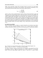
An interesting experimental demonstration is illustrated in Fig. 6, which shows the relationship between load-carrying
capacity, W, and for a hydrodynamic gas-lubricated journal bearing. Speed, viscosity, and eccentricity ratio were held
constant while the ambient pressure was reduced, thus producing higher values of . Notice that when the ambient
pressure was reduced to 9% of atmospheric, the load-carrying capacity was lowered by 40%.
Fig. 6 Example of relationship between load-carrying capacity, W, and for self-acting gas-
lubricated journal
bearing. Speed, viscosity, and eccentricity ratio held constant. Ambient pressure varied. Source: Ref 7
Definitions of Eccentricity Ratio and Clearance Modulus
In Fig. 1, O represents the center of the bearing and O' the center of the shaft. The distance O-O' is also designated as a;
for light loads and high operating speeds, the center of the shaft and bearing coincide, and a approaches zero. The ratio of
the distance a for any given operating condition to the machined-in radial clearance c of the bearing is called the
eccentricity ratio, .
For heavy loads or extremes of operation, such as low speed or very low viscosity, the journal becomes more eccentric in
the bearing and the distance a increases. The limit is where the journal just begins to make solid contact with the bearing,
or the distance a equals the radial clearance. The eccentricity ratio is then 1. The radial clearance in the journal bearing is
often designated as mr, where m is the clearance modulus of the bearing and r is the radius of the shaft or journal. The
value of m will usually range between 0.0005 and 0.003 mm/mm, with typical industrial-type bearings running between
0.001 and 0.0025 mm/mm.
In the analysis of fluid-film bearings using incompressible lubricants, the continuity relationship was satisfied by saying
that the volume of lubricant leaving the bearing was the same as the volume entering. With gas, of course, the volume
changes, so that continuity must be based on equality of mass. Thus the mass of lubricant leaving equals the mass
entering.
The basic Reynolds equation then becomes (Ref 8):
(Eq 4)
where is the mass density, x is the coordinate along the film in the direction of motion, z is the coordinate along the
bearing dimension perpendicular to the direction of motion (sometimes called the length of the bearing, l, or the width of
the bearing, b), p is the differential pressure, and h is the local differential film thickness.