sybex ccna fast pass 3rd edition 2007 phần 2 pps
Bạn đang xem bản rút gọn của tài liệu. Xem và tải ngay bản đầy đủ của tài liệu tại đây (3.08 MB, 51 trang )
1.5 Describe the purpose and basic operation of the protocols in the OSI and TCP
17
between hosts. Remember that none of the upper layers knows anything about networking or
network addresses. That’s the responsibility of the four bottom layers.
In Figure 1.8, you can see that it’s the four bottom layers that define how data is trans-
ferred through a physical wire or through switches and routers. These bottom layers also
determine how to rebuild a data stream from a transmitting host to a destination host’s
application.
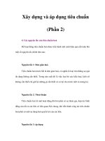
FIGURE 1.7 The upper layers
FIGURE 1.8 The lower layers
• Provides a user interface
• Presents data
• Handles processing such as encryption
• Keeps different applications’
• data separate
Application
Presentation
Session
Transport
Network
Data Link
Physical
• Combines packets into bytes and bytes into frames
• Provides access to media using MAC address
• Performs error detection not correction
• Provides logical addressing,
• which routers use for path determination
• Provides reliable or unreliable delivery
• Performs err
or correction before retransmit
• Moves bits between devices
• Specifies voltage, wire speed,
• and pin-out of cables
Transport
Network
Data Link
Physical
85711c01.fm Page 17 Thursday, September 27, 2007 11:17 AM
18
Chapter 1
Describe how a network works
The following network devices operate at all seven layers of the OSI model:
Network management stations (NMSs)
Web and application servers
Gateways (not default gateways)
Network hosts
Basically, the ISO is pretty much the Emily Post of the network protocol world. Just as Ms.
Post wrote the book setting the standards—or protocols—for human social interaction, the
ISO developed the OSI reference model as the precedent and guide for an open network pro-
tocol set. Defining the etiquette of communication models, it remains today the most popular
means of comparison for protocol suites.
The OSI reference model has seven layers:
Application layer (layer 7)
Presentation layer (layer 6)
Session layer (layer 5)
Transport layer (layer 4)
Network layer (layer 3)
Data Link layer (layer 2)
Physical layer (layer 1)
Figure 1.9 shows a summary of the functions defined at each layer of the OSI model. With
this in hand, you’re now ready to explore each layer’s function in detail.
FIGURE 1.9 Layer functions
In the next section, I’ll dive deeper into TCP and UDP that reside at the Transport layer.
85711c01.fm Page 18 Thursday, September 27, 2007 11:17 AM
1.6 Describe the impact of applications (Voice over IP and Video over IP) on a network
19
Exam Essentials
Understand the advantages of using layered models. The OSI model is hierarchical, and the
same benefits and advantages can apply to any layered model. The primary purpose of all such
models, especially the OSI model, is to allow different vendors’ networks to interoper-
ate.Remember that the OSI/DoD model is a layered approach.
Functions are divided into layers, and the layers are bound together. This allows layers to oper-
ate transparently to each other, that is, changes in one layer should not impact other layers.
1.6 Describe the impact of applications
(Voice over IP and Video over IP) on
a network
The main purpose of the Host-to-Host layer is to shield the upper-layer applications from the
complexities of the network. This layer says to the upper layer, “Just give me your data stream,
with any instructions, and I’ll begin the process of getting your information ready to send.”
The following sections describe the two protocols at this layer:
Transmission Control Protocol (TCP)
User Datagram Protocol (UDP)
By understanding how TCP and UDP work, you can interpret the impact of applications on
networks when using Voice and Video Over IP.
Transmission Control Protocol (TCP)
Transmission Control Protocol (TCP) takes large blocks of information from an application and
breaks them into segments. It numbers and sequences each segment so that the destination’s TCP
stack can put the segments back into the order the application intended. After these segments are
sent, TCP (on the transmitting host) waits for an acknowledgment of the receiving end’s TCP
virtual circuit session, retransmitting those that aren’t acknowledged.
Before a transmitting host starts to send segments down the model, the sender’s TCP stack
contacts the destination’s TCP stack to establish a connection. What is created is known as a
virtual circuit. This type of communication is called connection-oriented. During this initial
handshake, the two TCP layers also agree on the amount of information that’s going to be sent
before the recipient’s TCP sends back an acknowledgment. With everything agreed upon in
advance, the path is paved for reliable communication to take place.
TCP is a full-duplex, connection-oriented, reliable, and accurate protocol, but establishing
all these terms and conditions, in addition to error checking, is no small task. TCP is very com-
plicated and, not surprisingly, costly in terms of network overhead. And since today’s net-
works are much more reliable than those of yore, this added reliability is often unnecessary.
85711c01.fm Page 19 Thursday, September 27, 2007 11:17 AM
20
Chapter 1
Describe how a network works
TCP Segment Format
Since the upper layers just send a data stream to the protocols in the Transport layers, I’ll dem-
onstrate how TCP segments a data stream and prepares it for the Internet layer. When the
Internet layer receives the data stream, it routes the segments as packets through an internet-
work. The segments are handed to the receiving host’s Host-to-Host layer protocol, which
rebuilds the data stream to hand to the upper-layer applications or protocols.
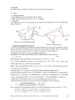
Figure 1.10 shows the TCP segment format. The figure shows the different fields within the
TCP header.
FIGURE 1.10 TCP segment format
The TCP header is 20 bytes long, or up to 24 bytes with options. You need to understand
what each field in the TCP segment is:
Source port The port number of the application on the host sending the data. (Port numbers
will be explained a little later in this section.)
Destination port The port number of the application requested on the destination host.
Sequence number A number used by TCP that puts the data back in the correct order or
retransmits missing or damaged data, a process called sequencing.
Acknowledgment number The TCP octet that is expected next.
Header length The number of 32-bit words in the TCP header. This indicates where the data
begins. The TCP header (even one including options) is an integral number of 32 bits in length.
Reserved Always set to zero.
Bit 0 Bit 15
Source port (16) Destination port (16)
Window (16)
Urgent (16)
Code bits (6)Reserved (6)
Checksum (16)
Header
length (4)
Sequence number (32)
Acknowledgment number (32)
Options (0 or 32 if any)
Data (varies)
Bit 16 Bit 31
24 bytes
85711c01.fm Page 20 Thursday, September 27, 2007 11:17 AM
1.6 Describe the impact of applications (Voice over IP and Video over IP) on a network
21
Code bits Control functions used to set up and terminate a session.
Window The window size the sender is willing to accept, in octets.
Checksum The cyclic redundancy check (CRC), because TCP doesn’t trust the lower layers
and checks everything. The CRC checks the header and data fields.
Urgent A valid field only if the Urgent pointer in the code bits is set. If so, this value indicates
the offset from the current sequence number, in octets, where the first segment of non-urgent
data begins.
Options May be 0 or a multiple of 32 bits, if any. What this means is that no options have
to be present (option size of 0). However, if any options are used that do not cause the option
field to total a multiple of 32 bits, padding of 0s must be used to make sure the data begins on
a 32-bit boundary.
Data Handed down to the TCP protocol at the Transport layer, which includes the upper-
layer headers.
Let’s take a look at a TCP segment copied from a network analyzer:
TCP - Transport Control Protocol
Source Port: 5973
Destination Port: 23
Sequence Number: 1456389907
Ack Number: 1242056456
Offset: 5
Reserved: %000000
Code: %011000
Ack is valid
Push Request
Window: 61320
Checksum: 0x61a6
Urgent Pointer: 0
No TCP Options
TCP Data Area:
vL.5.+.5.+.5.+.5 76 4c 19 35 11 2b 19 35 11 2b 19 35 11
2b 19 35 +. 11 2b 19
Frame Check Sequence: 0x0d00000f
Did you notice that everything I talked about earlier is in the segment? As you can see from
the number of fields in the header, TCP creates a lot of overhead. Application developers may
opt for efficiency over reliability to save overhead, so the User Datagram Protocol was also
defined at the Transport layer as an alternative.
85711c01.fm Page 21 Thursday, September 27, 2007 11:17 AM
22
Chapter 1
Describe how a network works
User Datagram Protocol (UDP)
If you were to compare the User Datagram Protocol (UDP) with TCP, the former is basically
the scaled-down economy model that’s sometimes referred to as a thin protocol. Like a thin
person on a park bench, a thin protocol doesn’t take up a lot of room—or in this case, much
bandwidth on a network.
UDP doesn’t offer all the bells and whistles of TCP either, but it does do a fabulous job of
transporting information that doesn’t require reliable delivery—and it does so using far fewer
network resources. (UDP is covered thoroughly in Request for Comments 768.)
The Requests for Comments (RFCs) form a series of notes, started in 1969,
about the Internet (originally the ARPAnet). The notes discuss many aspects
of computer communication; they focus on networking protocols, proce-
dures, programs, and concepts but also include meeting notes, opinion,
and sometimes humor.
There are some situations in which it would definitely be wise for developers to opt for UDP
rather than TCP. Remember the watchdog SNMP up there at the Process/Application layer?
SNMP monitors the network, sending intermittent messages and a fairly steady flow of status
updates and alerts, especially when running on a large network. The cost in overhead to estab-
lish, maintain, and close a TCP connection for each one of those little messages would reduce
what would be an otherwise healthy, efficient network to a dammed-up bog in no time!
Another circumstance calling for UDP over TCP is when reliability is already handled at the
Process/Application layer. Network File System (NFS) handles its own reliability issues, making
the use of TCP both impractical and redundant. But ultimately, it’s up to the application developer
to decide whether to use UDP or TCP, not the user who wants to transfer data faster.
UDP does not sequence the segments and does not care in which order the segments arrive
at the destination. But after that, UDP sends the segments off and forgets about them. It
doesn’t follow through, check up on them, or even allow for an acknowledgment of safe
arrival—complete abandonment. Because of this, it’s referred to as an unreliable protocol.
This does not mean that UDP is ineffective, only that it doesn’t handle issues of reliability.
Further, UDP doesn’t create a virtual circuit, nor does it contact the destination before
delivering information to it. Because of this, it’s also considered a connectionless protocol.
Since UDP assumes that the application will use its own reliability method, it doesn’t use any.
This gives an application developer a choice when running the Internet Protocol stack: TCP
for reliability or UDP for faster transfers.
So if you’re using Voice over IP (VoIP), for example, you really don’t want to use UDP,
because if the segments arrive out of order (very common in IP networks), they’ll just be passed
up to the next OSI (DoD) layer in whatever order they’re received, resulting in some seriously
garbled data. On the other hand, TCP sequences the segments so they get put back together
in exactly the right order—something that UDP just can’t do.
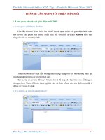
UDP Segment Format
Figure 1.11 clearly illustrates UDP’s markedly low overhead as compared to TCP’s hungry
usage. Look at the figure carefully—can you see that UDP doesn’t use windowing or provide
for acknowledgments in the UDP header?
85711c01.fm Page 22 Thursday, September 27, 2007 11:17 AM
1.6 Describe the impact of applications (Voice over IP and Video over IP) on a network
23
It’s important for you to understand what each field in the UDP segment is:
Source port Port number of the application on the host sending the data
Destination port Port number of the application requested on the destination host
Length Length of UDP header and UDP data
Checksum Checksum of both the UDP header and UDP data fields
Data Upper-layer data
FIGURE 1.11 UDP segment
UDP, like TCP, doesn’t trust the lower layers and runs its own CRC. Remember that the
Frame Check Sequence (FCS) is the field that houses the CRC, which is why you can see
the FCS information.
The following shows a UDP segment caught on a network analyzer:
UDP - User Datagram Protocol
Source Port: 1085
Destination Port: 5136
Length: 41
Checksum: 0x7a3c
UDP Data Area:
Z 00 01 5a 96 00 01 00 00 00 00 00 11 0000 00
C 2._C._C 2e 03 00 43 02 1e 32 0a 00 0a 00 80 43 00 80
Frame Check Sequence: 0x00000000
Notice that low overhead! Try to find the sequence number, ack number, and window size
in the UDP segment. You can’t because they just aren’t there!
Key Concepts of Host-to-Host Protocols
Since you’ve seen both a connection-oriented (TCP) and connectionless (UDP) protocol in action,
it would be good to summarize the two here. Table 1.1 highlights some of the key concepts that
you should keep in mind regarding these two protocols. You should memorize this table.
Bit 0 Bit 15
Source port (16) Destination port (16)
Length (16) Checksum (16)
Data (if any)
Bit 16 Bit 31
8 bytes
85711c01.fm Page 23 Thursday, September 27, 2007 11:17 AM
24
Chapter 1
Describe how a network works
A telephone analogy could really help you understand how TCP works. Most of us know
that before you speak to someone on a phone, you must first establish a connection with that
other person—wherever they are. This is like a virtual circuit with the TCP protocol. If you
were giving someone important information during your conversation, you might say, “You
know?” or ask, “Did you get that?” Saying something like this is a lot like a TCP acknowl-
edgment—it’s designed to get you verification. From time to time (especially on cell phones),
people also ask, “Are you still there?” They end their conversations with a “Goodbye” of
some kind, putting closure on the phone call. TCP also performs these types of functions.
Alternately, using UDP is like sending a postcard. To do that, you don’t need to contact the
other party first. You simply write your message, address the postcard, and mail it. This is
analogous to UDP’s connectionless orientation. Since the message on the postcard is probably
not a matter of life or death, you don’t need an acknowledgment of its receipt. Similarly, UDP
does not involve acknowledgments.
Exam Essentials
Remember the Host-to-Host layer protocols. Transmission Control Protocol (TCP) is a con-
nection-oriented protocol that provides reliable network service by using acknowledgments and
flow control. User Datagram Protocol (UDP) is a connectionless protocol that provides low over-
head and is considered unreliable.
Remember the Internet layer protocols. Internet Protocol (IP) is a connectionless protocol
that provides network address and routing through an internetwork. Address Resolution Pro-
tocol (ARP) finds a hardware address from a known IP address. Reverse ARP (RARP) finds
an IP address from a known hardware address. Internet Control Message Protocol (ICMP)
provides diagnostics and destination unreachable messages.
TABLE 1.1 Key Features of TCP and UDP
TCP UDP
Sequenced Unsequenced
Reliable Unreliable
Connection-oriented Connectionless
Virtual circuit Low overhead
Acknowledgments No acknowledgment
Windowing flow control No windowing or flow control
85711c01.fm Page 24 Thursday, September 27, 2007 11:17 AM
1.7 Interpret network diagrams
25
1.7 Interpret network diagrams
The best way to look at, build, and troubleshoot network diagrams is to use CDP. Cisco
Discovery Protocol (CDP) is a proprietary protocol designed by Cisco to help administrators
collect information about both locally attached and remote devices. By using CDP, you can
gather hardware and protocol information about neighbor devices, which is useful info for
troubleshooting and documenting the network.
In the following sections, I am going to discuss the CDP timer and CDP commands used to
verify your network.
Getting CDP Timers and Holdtime Information
The show cdp command (sh cdp for short) gives you information about two CDP global
parameters that can be configured on Cisco devices:
CDP timer is how often CDP packets are transmitted out all active interfaces.
CDP holdtime is the amount of time that the device will hold packets received from
neighbor devices.
Both Cisco routers and Cisco switches use the same parameters.
For this section, my 2811 used in this next example will have a hostname of
Corp, and it will have four serial connections to ISR routers named R1, R2, and
R3 (there are two connections to R1) and one FastEthernet connection to a
1242 access point with a hostname of just ap.
The output on the Corp router looks like this:
Corp#sh cdp
Global CDP information:
Sending CDP packets every 60 seconds
Sending a holdtime value of 180 seconds
Sending CDPv2 advertisements is enabled
Use the global commands cdp holdtime and cdp timer to configure the CDP holdtime and
timer on a router:
Corp(config)#cdp ?
advertise-v2 CDP sends version-2 advertisements
holdtime Specify the holdtime (in sec) to be sent in packets
log Log messages generated by CDP
run Enable CDP
source-interface Insert the interface's IP in all CDP packets
85711c01.fm Page 25 Thursday, September 27, 2007 11:17 AM
26
Chapter 1
Describe how a network works
timer Specify rate (in sec) at which CDP packets are sent run
Corp(config)#cdp holdtime ?
<10-255> Length of time (in sec) that receiver must keep this packet
Corp(config)#cdp timer ?
<5-254> Rate at which CDP packets are sent (in sec)
You can turn off CDP completely with the no cdp run command from the global configu-
ration mode of a router. To turn CDP off or on for an interface, use the no cdp enable and
cdp enable commands. Be patient—I’ll work through these with you in a second.
Gathering Neighbor Information
The show cdp neighbor command (sh cdp nei for short) delivers information about directly
connected devices. It’s important to remember that CDP packets aren’t passed through a Cisco
switch and that you only see what’s directly attached. So this means that if your router is con-
nected to a switch, you won’t see any of the devices hooked up to that switch.
The following output shows the show cdp neighbor command used on my ISR router:
Corp#sh cdp neighbors [Should this be neighbor (singular)?]no
Capability Codes: R - Router, T - Trans Bridge, B - Source Route Bridge
S - Switch, H - Host, I - IGMP, r - Repeater
Device ID Local Intrfce Holdtme Capability Platform Port ID
ap Fas 0/1 165 T I AIR-AP124 Fas 0
R2 Ser 0/1/0 140 R S I 2801 Ser 0/2/0
R3 Ser 0/0/1 157 R S I 1841 Ser 0/0/1
R1 Ser 0/2/0 154 R S I 1841 Ser 0/0/1
R1 Ser 0/0/0 154 R S I 1841 Ser 0/0/0
Corp#
Okay, we are directly connected with a console cable to the Corp ISR router, and the router
is directly connected to four devices. We have two connections to the R1 router. The device
ID shows the configured hostname of the connected device, the local interface is our interface,
and the port ID is the remote devices’ directly connected interface. All you get to view are
directly connected devices.
Table 1.2 summarizes the information displayed by the show cdp neighbor command for
each device.
TABLE 1.2 Output of the show cdp neighbor Command
Field Description
Device ID The hostname of the device directly connected.
Local Interface The port or interface on which you are receiving the CDP packet.
85711c01.fm Page 26 Thursday, September 27, 2007 11:17 AM
1.7 Interpret network diagrams
27
It is imperative that you can look at the output of a show cdp neighbors com-
mand and decipher the neighbor’s device (capability, i.e., router or switch),
model number (platform), your port connecting to that device (local inter-
face), and the port of the neighbor connecting to you (port ID).
Another command that’ll deliver the goods on neighbor information is the show cdp neighbors
detail command (show cdp nei de for short). This command can be run on both routers and
switches, and it displays detailed information about each device connected to the device you’re
running the command on. Check out this router output for an example:
Corp#sh cdp neighbors detail
Device ID: ap
Entry address(es): 10.1.1.2
Platform: cisco AIR-AP1242AG-A-K9 , Capabilities: Trans-Bridge IGMP
Interface: FastEthernet0/1, Port ID (outgoing port): FastEthernet0
Holdtime : 122 sec
Version :
Cisco IOS Software, C1240 Software (C1240-K9W7-M), Version 12.3(8)JEA,
RELEASE SOFTWARE (fc2)
Technical Support: />Copyright (c) 1986-2006 by Cisco Systems, Inc.
Compiled Wed 23-Aug-06 16:45 by kellythw
Holdtime The amount of time the router will hold the information before
discarding it if no more CDP packets are received.
Capability The capability of the neighbor, such as the router, switch, or repeater. The
capability codes are listed at the top of the command output.
Platform The type of Cisco device directly connected. In the previous output, a
Cisco 2500 router and Cisco 1900 switch are attached directly to the 2509
router. The 2509 only sees the 1900 switch and the 2500 router con-
nected through its serial 0 interface.
Port ID The neighbor device’s port or interface on which the CDP packets
are multicast.
TABLE 1.2 Output of the show cdp neighbor Command (continued)
Field Description
85711c01.fm Page 27 Thursday, September 27, 2007 11:17 AM
28
Chapter 1
Describe how a network works
advertisement version: 2
Duplex: full
Power drawn: 15.000 Watts
Device ID: R2
Entry address(es):
IP address: 10.4.4.2
Platform: Cisco 2801, Capabilities: Router Switch IGMP
Interface: Serial0/1/0, Port ID (outgoing port): Serial0/2/0
Holdtime : 135 sec
Version :
Cisco IOS Software, 2801 Software (C2801-ADVENTERPRISEK9-M),
Experimental Version 12.4(20050525:193634) [jezhao-ani 145]
Copyright (c) 1986-2005 by Cisco Systems, Inc.
Compiled Fri 27-May-05 23:53 by jezhao
advertisement version: 2
VTP Management Domain: ''
Device ID: R3
Entry address(es):
IP address: 10.5.5.1
Platform: Cisco 1841, Capabilities: Router Switch IGMP
Interface: Serial0/0/1, Port ID (outgoing port): Serial0/0/1
Holdtime : 152 sec
Version :
Cisco IOS Software, 1841 Software (C1841-IPBASE-M), Version 12.4(1c),
RELEASE SOFTWARE (fc1)
Technical Support: />Copyright (c) 1986-2005 by Cisco Systems, Inc.
Compiled Tue 25-Oct-05 17:10 by evmiller
advertisement version: 2
VTP Management Domain: ''
[output cut]
Corp#
First, we’re given the hostname and IP address of all directly connected devices. In addition
to the same information displayed by the show cdp neighbor command (see Table 1.5), the
show cdp neighbor detail command gives us the IOS version of the neighbor device.
85711c01.fm Page 28 Thursday, September 27, 2007 11:17 AM
1.7 Interpret network diagrams
29
Remember that you can see only the IP address of directly connected devices.
The show cdp entry * command displays the same information as the show cdp neighbor
details command. Here’s an example of the router output using the show cdp entry * command:
Corp#sh cdp entry *
Device ID: ap
Entry address(es):
Platform: cisco AIR-AP1242AG-A-K9 , Capabilities: Trans-Bridge IGMP
Interface: FastEthernet0/1, Port ID (outgoing port): FastEthernet0
Holdtime : 160 sec
Version :
Cisco IOS Software, C1240 Software (C1240-K9W7-M), Version 12.3(8)JEA,
RELEASE SOFTWARE (fc2)
Technical Support: />Copyright (c) 1986-2006 by Cisco Systems, Inc.
Compiled Wed 23-Aug-06 16:45 by kellythw
advertisement version: 2
Duplex: full
Power drawn: 15.000 Watts
Device ID: R2
Entry address(es):
IP address: 10.4.4.2
Platform: Cisco 2801, Capabilities: Router Switch IGMP
More—
[output cut]
There isn’t any difference between the show cdp neighbors detail and show cdp entry * com-
mands. However, the sh cdp entry * command has two options that the show cdp neighbors detail
command does not:
Corp#sh cdp entry * ?
protocol Protocol information
version Version information
| Output modifiers
<cr>
85711c01.fm Page 29 Thursday, September 27, 2007 11:17 AM
30
Chapter 1
Describe how a network works
Corp#show cdp entry * protocols
Protocol information for ap :
IP address: 10.1.1.2
Protocol information for R2 :
IP address: 10.4.4.2
Protocol information for R3 :
IP address: 10.5.5.1
Protocol information for R1 :
IP address: 10.3.3.2
Protocol information for R1 :
IP address: 10.2.2.2
The preceding output of the show cdp entry * protocols command can show you just the
IP addresses of each directly connected neighbor. The show cdp entry * version will show
you only the IOS version of your directly connected neighbors:
Corp#show cdp entry * version
Version information for ap :
Cisco IOS Software, C1240 Software (C1240-K9W7-M), Version
12.3(8)JEA, RELEASE SOFTWARE (fc2)
Technical Support: />Copyright (c) 1986-2006 by Cisco Systems, Inc.
Compiled Wed 23-Aug-06 16:45 by kellythw
Version information for R2 :
Cisco IOS Software, 2801 Software (C2801-ADVENTERPRISEK9-M),
Experimental Version 12.4(20050525:193634) [jezhao-ani 145]
Copyright (c) 1986-2005 by Cisco Systems, Inc.
Compiled Fri 27-May-05 23:53 by jezhao
Version information for R3 :
Cisco IOS Software, 1841 Software (C1841-IPBASE-M), Version 12.4(1c),
RELEASE SOFTWARE (fc1)
Technical Support: />Copyright (c) 1986-2005 by Cisco Systems, Inc.
Compiled Tue 25-Oct-05 17:10 by evmiller
More—
[output cut]
Although the show cdp neighbors detail and show cdp entry commands are very similar,
the show cdp entry command allows you to display only one line of output for each directly
connected neighbor, whereas the show cdp neighbor detail command does not. Next, let’s
look at the show cdp traffic command.
85711c01.fm Page 30 Thursday, September 27, 2007 11:17 AM
1.7 Interpret network diagrams
31
Documenting a Network Topology Using CDP
As the title of this section implies, I’m now going to show you how to document a sample net-
work by using CDP. You’ll learn to determine the appropriate router types, interface types, and
IP addresses of various interfaces using only CDP commands and the show running-config com-
mand. And you can only console into the Lab_A router to document the network. You’ll have
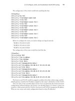
to assign any remote routers the next IP address in each range. Figure 1.12 is what you’ll use to
complete the documentation.
FIGURE 1.12 Documenting a network topology using CDP
In this output, you can see that you have a router with four interfaces: two FastEthernet
and two serial. First, determine the IP addresses of each interface by using the show
running-config command:
Lab_A#sh running-config
Building configuration
Current configuration : 960 bytes
!
version 12.2
service timestamps debug uptime
service timestamps log uptime
no service password-encryption
!
IP address
Fa0/0
S1
Fa0/1
.1
.1
.1
.1
S0/0
S0/1
Lab_A
Router
Int
IP address
Router
IP address
Router
Int Int
IP address
Router
Int
85711c01.fm Page 31 Thursday, September 27, 2007 11:17 AM
32
Chapter 1
Describe how a network works
hostname Lab_A
!
ip subnet-zero
!
!
interface FastEthernet0/0
ip address 192.168.21.1 255.255.255.0
duplex auto
!
interface FastEthernet0/1
ip address 192.168.18.1 255.255.255.0
duplex auto
!
interface Serial0/0
ip address 192.168.23.1 255.255.255.0
!
interface Serial0/1
ip address 192.168.28.1 255.255.255.0
!
ip classless
!
line con 0
line aux 0
line vty 0 4
!
end
With this step completed, you can now write down the IP addresses of the Lab_A router’s
four interfaces. Next, you need to determine the type of device on the other end of each of these
interfaces. It’s easy to do this—just use the show cdp neighbors command:
Lab_A#sh cdp neighbors
Capability Codes: R - Router, T - Trans Bridge, B - Source Route Bridge
S - Switch, H - Host, I - IGMP, r - Repeater
Device ID Local Intrfce Holdtme Capability Platform Port ID
Lab_B Fas 0/0 178 R 2501 E0
Lab_C Fas 0/1 137 R 2621 Fa0/0
Lab_D Ser 0/0 178 R 2514 S1
Lab_E Ser 0/1 137 R 2620 S0/1
Lab_A#
85711c01.fm Page 32 Thursday, September 27, 2007 11:17 AM
1.7 Interpret network diagrams
33
You’ve got a good deal of information now! By using both the show running-config and
show cdp neighbors commands, you know about all the IP addresses of the Lab_A router plus
the types of routers connected to each of the Lab_A router’s links and all the interfaces of the
remote routers.
And by using all the information gathered from show running-config and show cdp neighbors,
we can now create the topology in Figure 1.13.
FIGURE 1.13 Network topology documented
If we needed to, we could’ve also used the show cdp neighbors detail command to view the
neighbor’s IP addresses. But since we know the IP addresses of each link on the Lab_A router,
we already know what the next available IP address is going to be.
Exam Essentials
Understand when to use CDP. Cisco Discovery Protocol can be used to help you document
as well as troubleshoot your network.
Remember what the output from the show cdp neighbors command shows. The show
cdp neighbors command provides the following information: device ID, local interface,
holdtime, capability, platform, and port ID (remote interface).
192.168.21 .2/24
192.168.18 .2/24
2501
192.168.23 .2/24
2514
E0
Fa0/0
Fa0/0
2621
192.168.28.2/24
S0/1
S1
2620
Fa0/1
.1
.1
.1
.1
S0/0
S0/1
Lab_A
85711c01.fm Page 33 Thursday, September 27, 2007 11:17 AM
34
Chapter 1
Describe how a network works
1.8 Determine the path between two
hosts across a network
Once you create an internetwork by connecting your WANs and LANs to a router, you’ll need
to configure logical network addresses, such as IP addresses, to all hosts on the internetwork
so that they can communicate across that internetwork.
The term routing is used for taking a packet from one device and sending it through the net-
work to another device on a different network. Routers don’t really care about hosts—they
only care about networks and the best path to each network. The logical network address of
the destination host is used to get packets to a network through a routed network, and then
the hardware address of the host is used to deliver the packet from a router to the correct des-
tination host.
If your network has no routers, then it should be apparent that you are not routing. Routers
route traffic to all the networks in your internetwork. To be able to route packets, a router
must know, at a minimum, the following:
Destination address
Neighbor routers from which it can learn about remote networks
Possible routes to all remote networks
The best route to each remote network
How to maintain and verify routing information
The router learns about remote networks from neighbor routers or from an administrator.
The router then builds a routing table (a map of the internetwork) that describes how to find
the remote networks. If a network is directly connected, then the router already knows how
to get to it.
If a network isn’t directly connected to the router, the router must use one of two ways to
learn how to get to the remote network: static routing, meaning that someone must hand-type
all network locations into the routing table, or something called dynamic routing. In dynamic
routing, a protocol on one router communicates with the same protocol running on neighbor
routers. The routers then update each other about all the networks they know about and place
this information into the routing table. If a change occurs in the network, the dynamic routing
protocols automatically inform all routers about the event. If static routing is used, the admin-
istrator is responsible for updating all changes by hand into all routers. Typically, in a large
network, a combination of both dynamic and static routing is used.
Before we jump into the IP routing process, let’s take a look at a simple example that dem-
onstrates how a router uses the routing table to route packets out of an interface. We’ll be
going into a more detailed study of the process in the next section.
Figure 1.14 shows a simple two-router network. Lab_A has one serial interface and three
LAN interfaces.
Looking at Figure 1.14, can you see which interface Lab_A will use to forward an IP datagram
to a host with an IP address of 10.10.10.10?
85711c01.fm Page 34 Thursday, September 27, 2007 11:17 AM
1.8 Determine the path between two hosts across a network
35
FIGURE 1.14 A simple routing example
By using the command show ip route, we can see the routing table (map of the internet-
work) that Lab_A uses to make forwarding decisions:
Lab_A#sh ip route
[output cut]
Gateway of last resort is not set
C 10.10.10.0/24 is directly connected, FastEthernet0/0
C 10.10.20.0/24 is directly connected, FastEthernet0/1
C 10.10.30.0/24 is directly connected, FastEthernet0/2
C 10.10.40.0/24 is directly connected, Serial 0/0
The C in the routing table output means that the networks listed are “directly connected,”
and until we add a routing protocol—something like RIP, EIGRP, or the like—to the routers
in our internetwork (or use static routes), we’ll have only directly connected networks in our
routing table.
RIP and EIGRP are routing protocols and are covered in chapters 6 and 7
of the Sybex CCNA Study Guide 6
th
edition as well as in chapter x of this
FastPass book.
So let’s get back to the original question: By looking at the figure and the output of the rout-
ing table, can you tell what IP will do with a received packet that has a destination IP address
of 10.10.10.10? The router will packet-switch the packet to interface FastEthernet 0/0, and
this interface will frame the packet and then send it out on the network segment.
S0/0
10.10.40.1/24
Fa0/1
10.10.20.1/24
Fa0/0
10.10.10.1/24
Fa0/2
10.10.30.1/24
Lab_A
85711c01.fm Page 35 Thursday, September 27, 2007 11:17 AM
36
Chapter 1
Describe how a network works
Because we can, let’s do another example: Based on the output of the next routing table,
which interface will a packet with a destination address of 10.10.10.14 be forwarded from?
Lab_A#sh ip route
[output cut]
Gateway of last resort is not set
C 10.10.10.16/28 is directly connected, FastEthernet0/0
C 10.10.10.8/29 is directly connected, FastEthernet0/1
C 10.10.10.4/30 is directly connected, FastEthernet0/2
C 10.10.10.0/30 is directly connected, Serial 0/0
First, you can see that the network is subnetted and each interface has a different mask. And
I have to tell you—you just can’t answer this question if you can’t subnet! 10.10.10.14 would
be a host in the 10.10.10.8/29 subnet connected to the FastEthernet0/1 interface. If you don’t
understand, just go back and reread Chapter 3 of the Sybex CCNA Study Guide 6
th
Edition
if you’re struggling, and this should make perfect sense to you afterward.
I really want to make sure you understand IP routing because it’s super-important. So I’m
going to use this section to test your understanding of the IP routing process by having you
look at a couple of figures and answer some very basic IP routing questions.
Figure 1.15 shows a LAN connected to RouterA, which is, in turn, connected via a WAN
link to RouterB. RouterB has a LAN connected with an HTTP server attached.
FIGURE 1.15 IP routing example 1
The critical information you need to glean from this figure is exactly how IP routing will
occur in this example. Okay—we’ll cheat a bit. I’ll give you the answer, but then you should
go back over the figure and see if you can answer example 2 without looking at my answers.
1. The destination address of a frame, from HostA, will be the MAC address of the F0/0
interface of the RouterA router.
2. The destination address of a packet will be the IP address of the network interface card
(NIC) of the HTTP server.
3. The destination port number in the segment header will have a value of 80.
Fa0/0 Fa0/0
S0/0
RouterARouterB
HTTP Server
HostA
S0/0
85711c01.fm Page 36 Thursday, September 27, 2007 11:17 AM
1.8 Determine the path between two hosts across a network
37
That example was a pretty simple one, and it was also very to the point. One thing to
remember is that if multiple hosts are communicating to the server using HTTP, they must all
use a different source port number. That is how the server keeps the data separated at the
Transport layer.
Let’s mix it up a little and add another internetworking device into the network and then see if
you can find the answers. Figure 1.16 shows a network with only one router but two switches.
FIGURE 1.16 IP routing example 2
What you want to understand about the IP routing process here is what happens when
HostA sends data to the HTTPS server:
1. The destination address of a frame, from HostA, will be the MAC address of the F0/0
interface of the RouterA router.
2. The destination address of a packet will be the IP address of the network interface card
(NIC) of the HTTPS server.
3. The destination port number in the segment header will have a value of 443.
Notice that the switches weren’t used as either a default gateway or another destination.
That’s because switches have nothing to do with routing. I wonder how many of you chose the
switch as the default gateway (destination) MAC address for HostA? If you did, don’t feel
bad—just take another look with that fact in mind. It’s very important to remember that the
destination MAC address will always be the router’s interface—if your packets are destined
for outside the LAN, as they were in these last two examples.
Before we move into some of the more advanced aspects of IP routing, let’s discuss ICMP in
more detail, as well as how ICMP is used in an internetwork. Take a look at the network shown
in Figure 1.17. Ask yourself what will happen if the LAN interface of Lab_C goes down.
Lab_C will use ICMP to inform Host A that Host B can’t be reached, and it will do this by
sending an ICMP destination unreachable message. Lots of people think that the Lab_A router
would be sending this message, but they would be wrong because the router that sends the
message is the one with that interface that’s down is located.
Fa0/0
RouterA
HostA
Fa0/1
HTTPS Server
85711c01.fm Page 37 Thursday, September 27, 2007 11:17 AM
38
Chapter 1
Describe how a network works
FIGURE 1.17 ICMP error example
Let’s look at another problem: Look at the output of a corporate router’s routing table:
Corp#sh ip route
[output cut]
R 192.168.215.0 [120/2] via 192.168.20.2, 00:00:23, Serial0/0
R 192.168.115.0 [120/1] via 192.168.20.2, 00:00:23, Serial0/0
R 192.168.30.0 [120/1] via 192.168.20.2, 00:00:23, Serial0/0
C 192.168.20.0 is directly connected, Serial0/0
C 192.168.214.0 is directly connected, FastEthernet0/0
What do we see here? If I were to tell you that the corporate router received an IP packet
with a source IP address of 192.168.214.20 and a destination address of 192.168.22.3, what
do you think the Corp router will do with this packet?
If you said, “The packet came in on the FastEthernet 0/0 interface, but since the routing
table doesn’t show a route to network 192.168.22.0 (or a default route), the router will
discard the packet and send an ICMP destination unreachable message back out interface
FastEthernet 0/0,” you’re a genius! The reason it does this is because that’s the source LAN
where the packet originated from.
Exam Essentials
Understand the basic IP routing process. You need to remember that the frame changes at
each hop but that the packet is never changed or manipulated in any way until it reaches the
destination device.
Understand that MAC addresses are always local. A MAC (hardware) address will only be
used on a local LAN. It will never pass a router’s interface.
Understand that a frame carries a packet to only two places. A frame uses MAC (hardware)
addresses to send a packet on a LAN. The frame will take the packet to either a host on the LAN
or a router’s interface if the packet is destined for a remote network
Lab_A
Lab_B
Host A
E0 E0
Lab_C
Host B
E0
icmp
85711c01.fm Page 38 Thursday, September 27, 2007 11:17 AM
1.9 Describe the components required for network and Internet communications
39
1.9 Describe the components
required for network and Internet
communications
When a host transmits data across a network to another device, the data goes through encap-
sulation: It is wrapped with protocol information at each layer of the OSI model. Each layer
communicates only with its peer layer on the receiving device.
To communicate and exchange information, each layer uses Protocol Data Units
(PDUs). These hold the control information attached to the data at each layer of the model.
They are usually attached to the header in front of the data field but can also be in the trailer,
or end, of it.
Each PDU attaches to the data by encapsulating it at each layer of the OSI model, and each
has a specific name depending on the information provided in each header. This PDU infor-
mation is read only by the peer layer on the receiving device. After it’s read, it’s stripped off
and the data is then handed to the next layer up.
Figure 1.18 shows the PDUs and how they attach control information to each layer. This fig-
ure demonstrates how the upper-layer user data is converted for transmission on the network.
The data stream is then handed down to the Transport layer, which sets up a virtual circuit to
the receiving device by sending over a synch packet. Next, the data stream is broken up into
smaller pieces, and a Transport layer header (a PDU) is created and attached to the header of the
data field; now the piece of data is called a segment. Each segment is sequenced so the data
stream can be put back together on the receiving side exactly as it was transmitted.
FIGURE 1.18 Data encapsulation
Application
Presentation
Session
Transport
Network
Data Link
Physical
Segment
PDU
Packet
Frame
Bits
Upper layer dataTCP header
DataIP header
DataLLC header
DataMAC header
0101110101001000010
Upper layer data
FCS
FCS
85711c01.fm Page 39 Thursday, September 27, 2007 11:17 AM
40
Chapter 1
Describe how a network works
Each segment is then handed to the Network layer for network addressing and routing
through the internetwork. Logical addressing (for example, IP) is used to get each segment to the
correct network. The Network layer protocol adds a control header to the segment handed
down from the Transport layer, and what we have now is called a packet or datagram. Remem-
ber that the Transport and Network layers work together to rebuild a data stream on a receiving
host, but it’s not part of their work to place their PDUs on a local network segment—which is
the only way to get the information to a router or host.
It’s the Data Link layer that’s responsible for taking packets from the Network layer and
placing them on the network medium (cable or wireless). The Data Link layer encapsulates
each packet in a frame, and the frame’s header carries the hardware address of the source and
destination hosts. If the destination device is on a remote network, then the frame is sent to a
router to be routed through an internetwork. Once it gets to the destination network, a new
frame is used to get the packet to the destination host.
To put this frame on the network, it must first be put into a digital signal. Since a frame is
really a logical group of 1s and 0s, the Physical layer is responsible for encoding these digits into
a digital signal, which is read by devices on the same local network. The receiving devices will
synchronize on the digital signal and extract (decode) the 1s and 0s from the digital signal. At this
point, the devices build the frames, run a CRC, and then check their answer against the answer
in the frame’s FCS field. If it matches, the packet is pulled from the frame and what’s left of the
frame is discarded. This process is called de-encapsulation. The packet is handed to the Network
layer, where the address is checked. If the address matches, the segment is pulled from the packet
and what’s left of the packet is discarded. The segment is processed at the Transport layer, which
rebuilds the data stream and acknowledges to the transmitting station that it received each piece.
It then happily hands the data stream to the upper-layer application.
At a transmitting device, the data encapsulation method works like this:
1. User information is converted to data for transmission on the network.
2. Data is converted to segments and a reliable connection is set up between the transmitting
and receiving hosts.
3. Segments are converted to packets or datagrams, and a logical address is placed in the
header so each packet can be routed through an internetwork.
4. Packets or datagrams are converted to frames for transmission on the local network. Hard-
ware (Ethernet) addresses are used to uniquely identify hosts on a local network segment.
5. Frames are converted to bits, and a digital encoding and clocking scheme is used.
6. To explain this in more detail using the layer addressing, I’ll use Figure 1.19.
Remember that a data stream is handed down from the upper layer to the Transport layer.
As technicians, we really don’t care who the data stream comes from because that’s really a
programmer’s problem. Our job is to rebuild the data stream reliably and hand it to the upper
layers on the receiving device.
Before we go further in our discussion of Figure 1.19, let’s discuss port numbers and make
sure we understand them. The Transport layer uses port numbers to define both the virtual
circuit and the upper-layer process, as you can see from Figure 1.20.
85711c01.fm Page 40 Thursday, September 27, 2007 11:17 AM
1.9 Describe the components required for network and Internet communications
41
FIGURE 1.19 PDU and layer addressing
FIGURE 1.20 Port numbers at the Transport layer
The Transport layer takes the data stream, makes segments out of it, and establishes a reli-
able session by creating a virtual circuit. It then sequences (numbers) each segment and uses
acknowledgments and flow control. If you’re using TCP, the virtual circuit is defined by the
source port number. Remember, the host just makes this up starting at port number 1024
(0 through 1023 are reserved for well-known port numbers). The destination port number
defines the upper-layer process (application) that the data stream is handed to when the data
stream is reliably rebuilt on the receiving host.
Source IP
Destination
MAC
Source Port
Destination
Port
. . . Data
Destination
IP
Protocol . . . Segment
Source MAC Ether-Field Packet FCS
Segment
Packet
Frame
Bit 1011011100011110000
Source Port
Destination
Port
. . .
1028 23
Host A
Host Z
Defines upper layer
process or application
. . .
DPSP
Defines Virtual Circuit
85711c01.fm Page 41 Thursday, September 27, 2007 11:17 AM