AIRWAY MANAGEMENT IN EMERGENCIES - PART 3 pot
Bạn đang xem bản rút gọn của tài liệu. Xem và tải ngay bản đầy đủ của tài liệu tại đây (1.12 MB, 32 trang )
Sounds: A number of conditions associated
with abnormal upper and lower airway sounds
may cause difficulty with BMV.
A history of snoring has been correlated
with DMV.
21
As with the obese patient, this may
be associated with redundant oropharyngeal
tissues. Early placement of an OPA, and main-
taining a head-extended position will help.
Stridor is almost always a sign of patho-
logic airway obstruction and should be consid-
ered an ominous sign. Any patient presenting
with inspiratory or expiratory stridor should be
considered as potentially very difficult or impos-
sible to bag-mask ventilate.
The patient with “stiff”, poorly compliant
lungs, (often associated with wheezing or rales)
will present increased resistance to bag-mask
ventilation and requires higher than normal
insufflation pressure.
The presence of two or more of the factors
presented above significantly increases the
potential for DMV.
21
The true incidence of DMV
in the emergency department (ED) is not clear
but is likely greater than that seen with the
elective surgical population. In the operating
room, DMV has been reported to occur in up
to 5–8% of elective surgical patients.
19, 21
Inter-
estingly, the DMV rate is twice as high (15.5%)
in patients who were also described as difficult
intubations.
19
Prediction of difficulty with BMV is an
important component of the airway assessment,
as BMV remains the “go to” method of gas exchange
both before and between intubation attempts. It
also represents a vital decision node in airway
management in two ways:
A. Decision making: Anticipated difficulty
with BMV may point to the need for an
awake technique for intubation, especially
if difficulty with laryngoscopy is also pre-
dicted (see Chap. 11).
B. Defining the failed airway: In the setting
of failed intubation, the inability to maintain
the SaO
2
>90% with BMV defines failed
oxygenation, mandating proceeding with
rescue oxygenation via an extraglottic device
or cricothyrotomy (see Chap. 12).
One last implication of predicted difficulty
with BMV is the automatic need for an addi-
tional assistant, assuming a high probability of
requiring a two-person technique.
᭤ BMV TIPS AND PEARLS
Ideal Head and Neck Positioning
for BMV
Ideally, for BMV, the head and upper neck
should be extended
23
(a) to attain a more direct
path for the delivered volumes from face to tra-
chea, (b) to maintain longitudinal tension on
the lumen of the upper airway
24
and possibly,
(c) to increase retrolingual and retropalatal
space.
25
When studied, no additional benefit
was noted with elevation of the occiput (i.e.,
the “sniff” position) compared with simple head
tilt starting in the neutral position.
23
Gastric Insufflation
Protracted periods of BMV or poor technique
(e.g., delivering breaths during the expiratory
phase of the patient’s respiratory cycle; not
maintaining an adequately open upper airway;
or using excessive tidal volumes or positive
pressure) can lead to insufflation of the esoph-
agus and stomach. Gastric distention in turn
presents two problems:
• It predisposes to regurgitation of gastric con-
tents, potentially leading to aspiration, with
its sequellae.
• Particularly in children, but also in adults,
massive gastric distention can significantly
elevate and interfere with movement of the
diaphragm, in turn creating further difficulty
with BMV by impacting respiratory system
compliance. In extreme cases, gastric rupture
can occur.
OXYGEN DELIVERY DEVICES AND BAG-MASK VENTILATION 49
Gastric insufflation can be avoided by care-
ful attention to delivered tidal volumes, employ-
ing the lowest ventilation pressures possible
(below 20 cm H
2
O), and using airway adjuncts
such as the OPA and NPA. Evidence is emerg-
ing that especially in the cardiac arrest patient,
lower esophageal sphincter pressure decreases
rapidly from the normal 20 cm H
2
O to as little
as 5 cm H
2
O, underscoring the need to mini-
mize applied insufflation pressures.
26
Applica-
tion of cricoid pressure (see below) can also be
considered. Although most patients can be ade-
quately oxygenated and ventilated using good,
well-timed BMV technique, some gastric insuf-
flation is inevitable. BMV should therefore be
viewed as a “bridging” procedure to be used for
a limited period of time. If clinically significant
gastric distention is suspected, an oro- or naso-
gastric tube should be passed to decompress
the stomach.
Cricoid Pressure and BMV
Posterior pressure on the cricoid cartilage com-
presses the esophagus between the cartilagi-
nous ring of the cricoid and the body of the
C6 vertebra. It is often used to prevent passive
regurgitation of gastric contents during rapid-
sequence intubation, but can also be consid-
ered in the unconscious patient during BMV to
reduce inadvertent insufflation of air into the
stomach,
27
as discussed above. However, it must
be appreciated that cricoid pressure can cause
difficulty with BMV,
28, 29
especially if applied at
excessive pressures or in an upward direction.
30
If this is suspected, it should be at least tran-
siently released, to determine if that is the cause
of difficulty.
“AutoPEEP”
The patient with reactive airways disease experi-
ences air trapping and difficulty with exhalation.
In all patients, but particularly those with known
or suspected air trapping disease, attention must
be paid to allowing sufficient time for exhala-
tion during BMV. Failure to do this may result
in a buildup of intrathoracic pressure, which in
turn risks both cardiovascular collapse and baro-
trauma. Pressure may also be alleviated simply
by intermittently releasing the seal made by the
mask against the face.
Cervical Spine Precautions
and BMV
BMV can be performed safely in the patient who
is considered at risk for a cervical spine (C-spine)
injury, for example, the unconscious trauma
patient. However, radiologic studies have
shown that movement of the C-spine with BMV
is as much or more than that occurring with
laryngoscopic endotracheal intubation.
31–34
As
such, during BMV, manual in-line neck stabi-
lization (MILNS) should be applied. Head tilt
should be omitted: jaw lift is the only airway-
opening maneuver that should be used.
The Clinician with Small or
Tiring Hands
A one-person technique may be difficult or
impossible for the clinician with smaller hands,
or a clinician of average stature dealing with a
very large patient. In such situations, early use of
a two-person technique should be considered.
Laryngospasm
Laryngospasm is a tight and complete adduction
of the vocal cords. It sometimes occurs in response
to attempted airway manipulation in deeply
sedated patients, and may be more common in
the pediatric patient. Its effects can be dramatic,
with an almost total inability to bag-mask venti-
late the patient. If this is suspected, application
of CPAP with the BVM device will often help
break the spasm: simply continue to apply a tight
50 CHAPTER 4
seal with the mask, while maintaining light but
continuous positive pressure on the bag. Severe
or recalcitrant cases may require a small dose of
skeletal muscle relaxant, for example, succinyl-
choline 20 mg in the adult patient.
᭤ SUMMARY
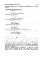
All clinicians with airway management respon-
sibilities must be able to assess the critically ill
patient for airway patency and adequacy of gas
exchange. BLS protocols should be followed to
open the airway, and if needed, positive-pressure
ventilation with BMV instituted. BMV must be
learned and practiced, and should not be looked
upon as an easy skill. As the clinician becomes
familiar with basic BMV, various adjuncts and
additions to BMV can be used, such as PEEP
and “pop-off” valves, depending on the prac-
tice environment. A formal approach should be
applied to the difficult BMV situation, and the
predictors of difficult BMV appreciated. Faced
with ongoing difficulty in performing BMV
and/or intubation, the clinician should consider
placing an extraglottic device such as a laryngeal
mask airway or Combitube.
REFERENCES
1. Dorges V, Wenzel V, Knacke P, Gerlach K. Com-
parison of different airway management strategies
to ventilate apneic, nonpreoxygenated patients.
Crit Care Med. 2003;31(3):800–804.
2. Gausche M, Lewis RJ, Stratton SJ, et al. Effect of
out-of-hospital pediatric endotracheal intubation
on survival and neurological outcome: a controlled
clinical trial. JAMA. 9, 2000;283(6):783–790.
3. Stockinger ZT, McSwain NE, Jr. Prehospital endo-
tracheal intubation for trauma does not improve
survival over bag-valve-mask ventilation. J Trauma.
2004;56(3):531–536.
4. Stapleton ER. Basic life support cardiopulmonary
resuscitation. Cardiol Clin. 2002;20(1):1–12.
5. Martin PD, Cyna AM, Hunter WA, et al. Training
nursing staff in airway management for resuscita-
tion. A clinical comparison of the facemask and
laryngeal mask. Anaesthesia. 1993;48(1):33–37.
6. Caples SM, Gay PC. Noninvasive positive pressure
ventilation in the intensive care unit: a concise
review. Crit Care Med. 2005;33(11):2651–2658.
7. Masip J, Roque M, Sanchez B, et al. Noninvasive
ventilation in acute cardiogenic pulmonary edema:
systematic review and meta-analysis. JAMA.
2005;294(24):3124–3130.
8. Mehta S, Hill NS. Noninvasive ventilation.
Am J Respir Crit Care Med. 2001;163(2):540–577.
9. Confalonieri M, Garuti G, Cattaruzza MS, et al. A chart
of failure risk for noninvasive ventilation in patients
with COPD exacerbation. Eur Respir J. 2005;25(2):
348–355.
10. Templier F, Dolveck F, Baer M, et al. Laboratory
testing measurement of FIO2 delivered by Boussi-
gnac CPAP system with an input of 100% oxygen.
Ann Fr Anesth Reanim. 2003;22(2):103–107.
11. Gabbott DA, Baskett PJ. Management of the airway
and ventilation during resuscitation. Br J Anaesth.
1997;79(2):159–171.
12. Levitan R, Ochroch EA. Airway management and
direct laryngoscopy. A review and update.
Crit Care Clin. 2000;16(3):373–388.
13. Roberts K, Porter K. How do you size a nasopha-
ryngeal airway. Resuscitation. 2003;56(1):19–23.
14. Stoneham MD. The nasopharyngeal airway. Assess-
ment of position by fibreoptic laryngoscopy.
Anaesthesia. 1993;48(7):575–580.
15. Muzzi DA, Losasso TJ, Cucchiara RF. Complication
from a nasopharyngeal airway in a patient with a
basilar skull fracture. Anesthesiology. 1991;74(2):
366–368.
16. Schade K, Borzotta A, Michaels A. Intracranial mal-
position of nasopharyngeal airway. J Trauma.
2000;49(5):967–968.
17. Part 4: Adult Basic Life Support. Circulation.
2005;112(24_suppl):IV19–IV34.
18. Wenzel V, Idris AH, Montgomery WH, et al. Rescue
breathing and bag-mask ventilation. Ann Emerg Med.
2001;37(4 Suppl):S36–S40.
19. Yildiz TS, Solak M, Toker K. The incidence and risk
factors of difficult mask ventilation. J Anesth.
2005;19(1):7–11.
20. Davidovic L, LaCovey D, Pitetti RD. Comparison of
1-versus 2-person bag-valve-mask techniques
for manikin ventilation of infants and children.
Ann Emerg Med. 2005;46(1):37–42.
21. Langeron O, Masso E, Huraux C, et al. Prediction of
difficult mask ventilation. Anesthesiology. 2000;92(5):
1229–1236.
OXYGEN DELIVERY DEVICES AND BAG-MASK VENTILATION 51
22. Walls RM, Murphy M. Identification of the diffi-
cult and failed airway. In: Walls RM, ed. Manual
of Emergency Airway Management. 2nd ed.
Philadelphia: Lippincott Willimas and Wilkins;
2004.
23. Morikawa S, Safar P, Decarlo J. Influence of the
headjaw position upon upper airway patency.
Anesthesiology. 1961;22:265–270.
24. Hillman DR, Platt PR, Eastwood PR. The upper air-
way during anaesthesia. Br J Anaesth. 2003;91(1):
31–39.
25. Isono S, Tanaka A, Ishikawa T, et al. Sniffing posi-
tion improves pharyngeal airway patency in anes-
thetized patients with obstructive sleep apnea.
Anesthesiology. 2005;103(3):489–494.
26. Gabrielli A, Wenzel V, Layon AJ, et al. Lower
esophageal sphincter pressure measurement dur-
ing cardiac arrest in humans: potential implications
for ventilation of the unprotected airway. Anesthe-
siology. 2005;103(4):897–899.
27. Wenzel V, Idris AH, Dorges V, et al. The respiratory
system during resuscitation: a review of the history,
risk of infection during assisted ventilation, respi-
ratory mechanics, and ventilation strategies for
patients with an unprotected airway. Resuscitation.
2001;49(2):123–134.
28. Palmer JHM, Ball DR. The effect of cricoid pressure
on the cricoid cartilage and vocal cords: an endo-
scopic study in anaesthetised patients. Anaesthe-
sia. 2000;55(3):263–268.
29. Hocking G, Roberts FL, Thew ME. Airway obstruc-
tion with cricoid pressure and lateral tilt. Anaes-
thesia. 2001;56(9):825–828.
30. Hartsilver EL, Vanner RG. Airway obstruction with
cricoid pressure. Anaesthesia. 2000;55(3):208–11.
31. Brimacombe J, Keller C, Kunzel KH, et al. Cervical
spine motion during airway management: a cine-
fluoroscopic study of the posteriorly destabilized
third cervical vertebrae in human cadavers. Anesth
Analg. 2000;91(5):1274–1278.
32. Aprahamian C, Thompson BM, Finger WA, et al.
Experimental cervical spine injury model: evalua-
tion of airway management and splinting tech-
niques. Ann Emerg Med. 1984;13(8):584–587.
33. Donaldson WF 3rd, Heil BV, Donaldson VP, et al.
The effect of airway maneuvers on the unstable
C1-C2 segment. A cadaver study. Spine. 1997;22(11):
1215–1218.
34. Hauswald M, Sklar DP, Tandberg D, et al. Cervical
spine movement during airway management:
cinefluoroscopic appraisal in human cadavers.
Am J Emerg Med. 1991;9(6):535–538.
52 CHAPTER 4
Chapter 5
Tracheal Intubation by Direct
Laryngoscopy
53
• Cervical spine immobilization will often
lead to an “epiglottis-only,” Grade 3 view
during direct laryngoscopy.
• To avoid patient morbidity, esophageal
intubations must be immediately recognized
and corrected.
᭤ INTRODUCTION
This chapter will review direct laryngoscopy and
intubation, including the initial response to
encountered difficulty. Direct laryngoscopy (DL)
is so named because it results ideally in direct
line-of-sight visualization of the glottis (Fig. 5–1).
While DL is only one method of facilitating defin-
itive airway management, it is still the procedural
standard for intubation in emergencies, and as
such is deserving of a detailed discussion. Alter-
native intubation techniques, including blind naso-
tracheal intubation, are discussed in later chapters.
᭤ PREPARATION FOR
ENDOTRACHEAL INTUBATION
The adage that “your first shot is your best shot”
is very applicable to laryngoscopy and intuba-
tion. Prior to proceeding with any intubation, it
is essential that the following preparations have
been undertaken:
᭤ KEY POINTS
• Direct laryngoscopy remains the proce-
dural standard for emergency intubation.
• The clinician should always psychologi-
cally prepare for a difficult airway, in an
attempt to “anticipate the unanticipated.”
• Special attention must be paid to positioning
the morbidly obese patient to facilitate
direct laryngoscopy.
• Cricoid pressure and external laryngeal
manipulation (ELM) are two separate
maneuvers done on two separate structures,
for different purposes.
• Failure to engage the hyoepiglottic liga-
ment in the vallecula is a probable cause
of the novice failing to achieve an ade-
quate view during direct laryngoscopy.
• Head lift, two-handed laryngoscopy
and ELM represent three ways to use
two hands on the fir s t intubation
attempt (“3–2–1”).
• Beware the “pseudolarynx,” especially in
young children.
• A tracheal tube introducer (“bougie”) or
fiberoptic stylet can be used on the first
intubation attempt when “best look” direct
laryngoscopy has failed to yield an ade-
quate view.
Copyright © 2008 by The McGraw-Hill Companies, Inc. Click here for terms of use.
A. Equipment should be assembled and imme-
diately available for management of either a
standard or unanticipated very difficult airway.
If possible, this equipment should be pre-
pared prior to the patient’s arrival. Ideally, a
dedicated airway equipment cart with all
the necessary tools, checked daily, should
be a fixture in most acute-care areas.
B. The patient and clinician performing the
intubation should be positioned in the
optimal (allowable) position for direct laryn-
goscopy.
C. The patient has been optimally preoxy-
genated.
D. Large-bore intravenous (IV) access has
been obtained and a fluid bolus delivered,
when appropriate.
E. Drugs needed to facilitate airway manage-
ment are available. Care should be taken to
match the drug type and dosage with the
patient and any acute or underlying chronic
conditions.
F. Personnel: Airway management is not a
one-person job. At least one assistant is nec-
essary to help, guided by specific directions.
If problems are anticipated, this should be
communicated to the team, and roles assigned
before getting started.
᭤ EQUIPMENT FOR TRACHEAL
INTUBATION
A well-equipped airway cart is not useful unless
it is at the bedside and its contents are familiar.
The following mnemonic may be helpful to
ensure that essential pieces of equipment are
immediately available: STOP “I” “C” BARS.
Suction—Rigid tonsillar suction is vital, turned
on and placed in close proximity to the
patient’s head. If there is a high likelihood
of encountering copious amounts of blood
or regurgitated matter, two running suctions
are not excessive. The suction tubing must
54 CHAPTER 5
Figure 5–1. Direct laryngoscopy is so-named as it affords a direct line-of-sight view from the
clinician’s eye to the laryngeal inlet.
be connected to an appropriate wall unit.
The rigid suction catheter should be checked
to see if it has a thumb port that must be
occluded to work effectively.
Tubes—An appropriately sized endotracheal
tube (ETT, e.g., adult female 7.0; adult male
8.0 internal diameter, [ID]) is prepared, as
well as a tube a half or full size smaller.
Rarely is a larger tube size required in an
adult patient. A 10 cc syringe is attached to
the pilot line, and the cuff integrity checked
by fully inflating, then deflating it. The ETT
tip can be lubricated with 2% lidocaine jelly
or other water soluble lubricant. For all emer-
gency intubations, a lubricated stylet should
be inserted into the ETT. If a curved Mac-
intosh blade is used, the stylet curve should
not exceed the default curvature of the ETT.
Alternatively, and in particular for a straight
blade, a “straight to cuff” shape will be ben-
eficial, whereby the tube is styletted
straight, with a 25–35° upward bend placed
just proximal to the cuff
1
(Fig. 5–2). For pedi-
atric patients, the Broselow tape can be con-
sulted for appropriate ETT sizing.
Oxygen and positive pressure—A manual
resuscitator with oxygen reservoir bag,
attached to high flow O
2,
should be avail-
able. As the only source of positive pressure
ventilation, this device should be checked
by occluding the patient end with a finger
and squeezing the self-inflating bag, feeling
for the positive pressure thus developed.
The reservoir bag should be distended.
Pharmacology—All the drugs that could possi-
bly be needed should be drawn up and
labeled. This may include drugs needed for
topical airway anesthesia, IV sedation, or
rapid-sequence intubation (RSI), including
induction agent and muscle relaxant. The
armamentarium should always include an
agent to treat postintubation hypotension—
merely instituting positive pressure ventila-
tion can interfere with venous return and
TRACHEAL INTUBATION BY DIRECT LARYNGOSCOPY 55
Figure 5–2. “Straight to cuff” stylet preparation of the ETT (above) compared to natural curve
(below).
cause hypotension, particularly in the vol-
ume-depleted patient.
Intravenous access—Good IV access (ideally
18G or larger) should be in situ, free-
flowing and not on a pump. It is rare that
a patient will not benefit from a fluid bolus
of 10–20 mL/kg prior to intubation.
Connect to monitors and Confirmation—During
intubation, the patient should ideally be mon-
itored with an electrocardiogram (ECG) tracing,
noninvasive blood pressure cuff (cycling at
intervals of no longer than 3 minutes), and a
pulse oximeter. In addition, objective means
for confirming tracheal location of the ETT
should be available, for example, capnometry
and/or an esophageal detector device.
Blades and Bougie—The laryngoscope should
be checked for bright light intensity. Sev-
eral blades should be available. The #3 Mac-
intosh (curved) blade will be useful as a
default blade, with the #4 for larger males.
To those familiar with it, a straight blade
(e.g., Miller, Phillips, or Wisconsin) can be
a useful primary or alternative blade. A tra-
cheal tube introducer (bougie) should be
within easy reach during all emergency intu-
bation attempts.
Alternative intubation device—In addition to
the bougie, during every emergency intuba-
tion attempt, equipment for an alternative
intubation technique should be available for
immediate use. Examples include the LMA
Fastrach
TM
(Intubating Laryngeal Mask Air-
way [ILMA]), fiberoptic optical stylet, or Tra-
chlight. These devices all require prepara-
tion by someone familiar with their use. If
the patient is being bag-mask ventilated
with difficulty in between intubation
attempts, the primary clinician will not be
available to prepare this equipment.
Rescue oxygenation technique—A Laryngeal
Mask Airway (e.g., LMA Classic
TM
, ProSeal,
Supreme, or Fastrach), Combitube, or other
extraglottic device is useful as a rescue oxy-
genation tool. One such device should be
sized for the patient and within arm’s reach
for the infrequent failed intubation or failed
oxygenation (Chap. 12) situation.
Surgical (i.e., cricothyrotomy) technique—For
most intubations, simply knowing the equip-
ment’s location and how to use it is adequate
preparation. However, for anticipated very
difficult situations, it may be appropriate to
have this equipment out and opened: a com-
ponent of the so-called “double set-up”.
᭤ POSITIONING FOR
LARYNGOSCOPY AND
INTUBATION
The clinician should be optimally positioned
before an intubation attempt, as should the patient.
Clinician Positioning
Comparisons of the posture of experienced and
novice laryngoscopists have observed the fol-
lowing: experienced clinicians stand further
back, with straighter backs and arms,
2
and hold
the laryngoscope closer to the base of the
blade
3
(Fig. 5–3). During direct laryngoscopy,
the laryngoscopist’s arm should be only mod-
estly flexed at the elbow and adducted, and not
bent at right angles and abducted. Better mechan-
ical advantage is then developed by the applica-
tion of a more in-line axial force through the arm
to the handle of the laryngoscope. Once a view
of the laryngeal inlet is obtained, some clinicians
elect to keep the arm adducted against the trunk
for additional support. This position of the arm is
consistent with the optimal distance from the
laryngoscopist’s eye to the patient’s glottis of
approximately 16–18 inches. Attention to clinician
positioning may help deliver favorable mechanical
and visual advantage during laryngoscopy.
Patient Positioning
Three aspects of patient positioning are crucial.
Failure to observe these positioning principles
may make obtaining a good view at laryn-
goscopy more difficult.
56 CHAPTER 5
A. “Up-down,” referring to stretcher height.
Often overlooked, the patient should be at the
appropriate height—with the middle of the
patient’s head at the level of the clinician’s belt
buckle.
B. “North-south”: the patient’s head should
be positioned as close as possible to the
upper (“north”) end of the stretcher.
C. “Sniff,” that is, head and neck positioning.
Classic teaching suggests placing the head
TRACHEAL INTUBATION BY DIRECT LARYNGOSCOPY 57
Figure 5–3. Clinician positioning during direct laryngoscopy: relatively straight back; modestly
flexed, adducted elbow, and a grip on the laryngoscope handle close to the blade.
and neck in the “sniffing” position for direct
laryngoscopy. When not contraindicated by
C-spine precautions, this involves flexing
the neck at the cervico-thoracic junction,
with extension of the neck at the upper few
cervical vertebrae and head at the occipito-
cervical junction. This will help align airway
axes, in turn helping attain a direct line-of-
sight view from the clinician’s eye to the laryn-
geal inlet (Fig. 3–8, Chap. 3). The sniffing
position can be attained by placing folded
blankets (about 4”/8 cm high) under the
patient’s occiput and/or lifting the head dur-
ing laryngoscopy, using the right hand under
the occiput.
The axis alignment sought by placing the
patient in the sniffing position can be exter-
nally referenced. Observing the patient from
the side, when the external auditory meatus is
lined up horizontally with the sternal notch, the
patient is generally well positioned for laryn-
goscopy in a good “sniff” position (Figs. 5–4 A
and B). This same “ear-to-sternum” positioning
58 CHAPTER 5
Figures 5–4. In contrast to the positioning of the patient in the neutral position (A), a line
drawn from the external auditory meatus to the patient’s sternum (“ear to sternum” line) will
give a rough indication of good positioning for direct laryngoscopy (B).
A
B
is also key to positioning the morbidly obese
patient
4
(see next section). While some recent
publications have suggested that cervicotho-
racic flexion is not a necessary component of
optimal positioning for laryngoscopy,
5–7
other
studies challenge this contention by suggest-
ing the utility of a head lift
8,9
in improving laryn-
geal view.
᭤ POSITIONING IN SPECIAL
SITUATIONS
C-Spine Precautions
In the patient requiring C-spine precautions,
the sniff position is not an option. DL under
these conditions will be more difficult, with an
expected incidence of blind, Grade 3 views
(no part of the glottis visible) of 20%–25%
10
with application of manual in-line neck stabi-
lization (MILNS). The incidence of Grade 3
views increases to 50% or more
10, 11
with a cer-
vical collar applied. For this reason, during
attempts at laryngoscopy and intubation,
MILNS should be substituted for the cervical
collar, as the latter increases difficulty by also
interfering with mouth opening. Note that the
function of in-line stabilization is as a reminder
to the laryngoscopist to minimize movement,
not necessarily to preclude any movement
whatsoever.
Morbid Obesity
Airway management in the morbidly obese
patient can be difficult in terms of bag-mask ven-
tilation (BMV), laryngoscopy and intubation, as
well as cricothyrotomy. In this population, unless
the patient is well positioned, during laryn-
goscopy, the handle of the laryngoscope may
abut the chest wall. Specially made short handles
can be used in this situation but are usually unnec-
essary when the patient is properly positioned.
Such positioning can be attained by building a
ramp with folded blankets (Fig. 5–5). Five to seven
folded blankets are placed under the occiput, 3–5
under the shoulders, and 1–3 under the scapulae.
This will elevate the face above the chest wall
and eliminate the concern of the handle hitting
the chest. During “ramping,” the unsupported
arms are allowed to fall to the side, taking with
them additional soft tissue from the anterior chest.
These benefits cannot be accomplished by
simply raising the head of the bed, nor by just lift-
ing the head of the obese patient at laryngoscopy.
Ramping is required in the morbidly obese patient
to achieve the previously mentioned “ear to
sternum” positioning
4
(Fig. 5–6 A and B).
Pregnancy
The patient in advanced stages of pregnancy
must be positioned with a right hip wedge.
TRACHEAL INTUBATION BY DIRECT LARYNGOSCOPY 59
Figure 5–5. A “ramp” created with folded blankets for positioning a morbidly obese patient
prior to laryngoscopy.
Tipping the gravid uterus to the left will help
avoid compression of the aorta and inferior
vena cava, which can otherwise cause supine
hypotension syndrome. There is also a higher
incidence of difficult laryngoscopy and intu-
bation in the obstetrical population,
12
and
pregnant patients in the second and third
trimesters should be considered at high risk for
passive regurgitation.
Both morbidly obese and third trimester
pregnant patients have a limited functional
residual capacity, and can be expected to
60 CHAPTER 5
Figure 5–6. A morbidly obese patient (A) before and (B) after positioning on a “ramp” of folded
blankets. Note the “ear-sternum” line before and after.
A
B
desaturate quickly when rendered apneic, for
example, during an RSI.
The Patient in Extreme Respiratory
Distress
The acutely dyspneic patient will not tolerate
the supine position. If an awake intubation is
planned, the patient can be intubated in the sit-
ting or semisitting position using DL or other
intubation technique. In this situation, the clin-
ician may need to be positioned on a chair at
the patient’s head (Fig. 5–7). If an RSI is planned,
the patient will need to be in the sitting position
until loss of consciousness occurs with the
induction agent.
TRACHEAL INTUBATION BY DIRECT LARYNGOSCOPY 61
Figure 5–7. Sitting position direct laryngoscopy. Note laryngoscopist initially guiding laryngoscope
blade with fingers of right hand.
The Pediatric Patient
The neonate, with its large head and occiput
relative to the thorax, will often end up with the
neck excessively flexed, if placed supine on a
table. This is the one situation in which a folded
towel may need to be placed under the shoul-
ders, to decrease lower C-spine flexion to the
same degree that is needed in the adult. The
toddler and young child (to approximately
age six) will be well-positioned merely placed
with the head flat on a table. Above age six,
positioning with the usual towel or folded
blanket under the occiput will be needed.
᭤ PREOXYGENATION
During the preparation phase, the patient
should receive as close to 100% O
2
as possible.
Holding a manual resuscitator (supplying O
2
at 15 L/min, with a functioning O
2
reservoir
system) firmly on the face is ideal. If the
patient’s spontaneous ventilations are felt to
be inadequate, timed inspiratory assisted ven-
tilation may be required. Obviously, in the
apneic patient, positive pressure ventilation
will be needed. Preoxygenation is a vitally
important step. Unintentionally omit-
ting this step puts the patient at risk of
profound hypoxemia during attempted
intubation.
᭤ DIRECT LARYNGOSCOPY
Laryngoscopes and Blades
The laryngoscope used for DL consists of a blade
and handle: the handle houses the power supply
and sometimes the light source. Generally the
laryngoscope blade snaps on to the top of a
handle. Rotating the blade to a position 90° to
the handle activates the illumination supply,
which is delivered toward the tip of the blade.
Some blades have a distal bulb-on-blade design,
while others transmit light from a bulb located
in the handle to the blade tip via a fiberoptic
bundle. A fiberoptic laryngoscope with a
rechargeable battery system is likely the most
dependable and has the potential to provide the
brightest lighting. Blades can be reusable or dis-
posable. Disposable blades are made of plastic
or steel. As the most important piece of intuba-
tion equipment, the laryngoscope should be of
reliable quality.
Familiar to many clinicians, the Macintosh
blade (Fig. 5–8) is curved, designed to partially
conform to the shape of the tongue. It is most
often used by placing the blade tip in the val-
lecula, at the junction of the base of the tongue
and origin of the epiglottis. As the blade tip is
pressed into this space and lifted, pressure on
the hyoepiglottic ligament will help indirectly
lift the epiglottis anteriorly, exposing the
underlying glottic opening. A size 3 Macintosh
blade will be appropriate in the majority of
adult patients, although in larger patients, espe-
cially those with long necks, a Macintosh 4 blade
may be needed. Also note that curved blades
can be used to directly “pick up” or elevate the
epiglottis.
Straight laryngoscope blades (Fig. 5–9) such
as the Miller, Phillips, or Wisconsin are
designed primarily to displace the tongue to
the left and directly elevate the epiglottis, thus
exposing the vocal cords. Often used as the
blades of choice in pediatric patients, they can
also be useful in the adult patient with an “ante-
rior” larynx, small mandible, large tongue, or
prominent central incisors.
13
Many straight
blade aficionados prefer its use by a para-
glossal approach, whereby the blade is placed
alongside the tongue, on its right. This
approach has been shown to be effective in
some situations where curved blade laryn-
goscopy had failed.
14
Finally, specialty blades exist to help in dif-
ficult situations. The McCoy blade, also known
as the levering tip or CLM (Corazelli-London-
McCoy) blade, has the basic shape of the
Macintosh, but in addition, features a levering
62 CHAPTER 5
distal tip. When an activating lever is depressed
toward the laryngoscope handle (Figs. 5–10 A
and B), the blade tip levers upward, helping
to elevate the epiglottis (Figs. 5–11 A and B).
The literature suggests it may be useful in
converting Grade 3 views to 2 or better, par-
ticularly when caused by applied manual in-line
stabilization.
15–18
TRACHEAL INTUBATION BY DIRECT LARYNGOSCOPY 63
Figure 5–8. Macintosh size 3 and 4 (adult) curved blades.
Figure 5–9. From left to right, Wisconsin, Phillips, and Miller straight blades.
Figure 5–10. A, B The McCoy (CLM) blade, (A) in the neutral and (B) partially activated positions.
A
B
A
B
Figure 5–11. Fluoroscopic images of the McCoy blade (A) before and (B) after partial blade tip
activation (the arrow in both images points to the epiglottis).
64 CHAPTER 5
TRACHEAL INTUBATION BY DIRECT LARYNGOSCOPY 65
Direct Laryngoscopy Technique:
General Comments
In performing DL, a few points are noteworthy:
A. To successfully perform direct laryngoscopy,
the clinician must be very familiar with the
anatomy of the oropharynx and laryngeal
inlet (reviewed in Chapter 3). A sound
knowledge of the anatomy will help the
clinician obtain an optimal view during
laryngoscope blade placement.
B. As emphasized earlier, the patient and the
clinician should be properly positioned,
with the stretcher elevated, the patient at
the head of the bed and the head and neck
in the sniff position (if not contraindicated).
Optimal positioning should be undertaken
prior to the first attempt at laryngoscopy,
and not deferred until difficulty has already
been encountered.
C. A cross-finger “scissor” technique is useful to
help open the mouth for initial blade insertion:
the thumb pushes the mandible/lower teeth
caudad to open the mouth, while the index fin-
ger crosses over the thumb to provide counter-
pressure on the maxilla/upper teeth (Fig. 5–12).
D. The laryngoscope handle should be held
close to the blade. Better mechanical advan-
tage will result and there will be less ten-
dency to lever back with the scope.
E. Following initial blade insertion, the clini-
cian’s right hand can be placed under the
patient’s occiput: with this hand concomi-
tantly lifting the head, additional lower neck
flexion and head extension can be under-
taken, (i.e., exaggerated “sniff”), often help-
ing to expose the cords during laryngoscopy.
Figure 5–12. Cross-finger mouth opening technique. This will help with oropharyngeal airway,
extraglottic device, and laryngoscope blade insertion.
Direct Laryngoscopy Technique:
Curved/Macintosh Blade
The laryngoscope handle is held in the left
hand. Dentures, if present, should be removed.
The patient’s mouth is opened with the right
hand, using the previously described cross-
finger technique. The blade should be inserted
on the right side of the tongue (Figs. 5–13 A,
B, and C) and is advanced to its base. This
should happen slowly and deliberately, taking
time to identify anatomy at the blade tip—with
adequate preoxygenation, there is no rush.
This “identify-as-you-go” technique will help
avoid placing the blade too far, an error com-
monly committed by the novice clinician. As
the base of the tongue is approached, some
traction is exerted along the long axis of the
laryngoscope handle (Figure 5–1) to start com-
pressing the tongue (Figs. 5–14 A, B and C).
66 CHAPTER 5
Figure 5–13. Direct laryngoscopy: Initial blade insertion—(A) on a model, (B) in a human sub-
ject, and (C) under fluoroscopy.
A
B
C
Figures 5–14. A, B, C. Direct laryngoscopy: Blade advancement and tongue compression,
looking for landmarks—(A) on a model, (B) in a human subject, and (C) under fluoroscopy.
A
B
C
A view of the epiglottis is sought: it is an
important landmark, needed to guide subse-
quent blade placement. After the epiglottis is
identified, the tip of the blade is advanced into
the vallecula (the space at the junction of the
base of the tongue and the origin of the epiglottis,
Figs. 5–15 A, B, and C). Once the blade is
placed fully into the vallecula, the blade tip is
centered, by moving it to the left. This will fur-
ther displace the tongue to the left. With the
blade tip now seated in the vallecula, addi-
tional lift can be applied along the longitudi-
nal axis of the laryngoscope handle (Figs. 5–16
A and B). The handle should generally not
TRACHEAL INTUBATION BY DIRECT LARYNGOSCOPY 67
A
B
C
Figures 5–15. Direct laryngoscopy: Identification of epiglottis and blade tip advancement into
vallecula—(A) on a model, (B) in a human subject, and (C) under fluoroscopy.
A B
Figure 5–16. (A) Curved blade tip placement in the vallecula, with subsequent traction along
the long axis of the laryngoscope handle (B), indicated by the arrow. Note the resultant indi-
rect elevation of the epiglottis.
68 CHAPTER 5
exceed an angle of about 30° to the floor.
Thus lifting forward along the handle’s axis
has two effects: (a) it will further compress the
tongue out of the way into the submandibular
space, and (b) the blade tip will place pressure
on the underlying hyoepiglottic ligament, in
turn helping to lift the epiglottis, revealing the
vocal cords beneath (Figs. 5–17 A, B and C). It
should be noted that if a chosen blade is too
short to successfully contact the hyoepiglottic
ligament at the junction of the tongue base and
epiglottis, the epiglottis may not move up and
out of the way (Figs. 5–18 A and B). If this is
suspected, a longer blade should be used.
Failure to engage the hyoepiglottic ligament in
the vallecula is a probable cause of the novice
failing to achieve an adequate view during direct
laryngoscopy. Conversely, too long a blade
can occasionally trap and downfold the
epiglottis, artificially creating a Grade 3 view.
The laryngoscope should never be levered
back while attempting to attain a view at laryn-
goscopy. This puts the upper teeth at risk of
damage, and also decreases the space available
for initial tube passage through the mouth.
Direct Laryngoscopy Technique:
Straight Blade
The straight blade is often used to displace
the tongue laterally, followed by direct lifting
of the epiglottis to expose the larynx (Fig. 5–19).
Using this “paraglossal,” or alongside-the-tongue
approach, the blade is inserted from the right
side of the mouth (Fig. 5–20) and advanced
along the right margin of the tongue. With the
tongue displaced to the left, the jaw is lifted by
traction along the axis of the laryngoscope
handle. Two schools of thought exist about sub-
sequent glottic exposure: one suggests advancing
the blade as far as it will go (i.e., down the
upper esophagus), then withdrawing until the
cords “pop” into view, while the other espouses
an “identify as you go” method, as is the case
with curved blade placement. With this latter
technique, once the epiglottis is identified, the
blade tip is “scooped” beneath the epiglottis to
achieve its direct elevation (Fig. 5–21).
The view of the cords at the blade tip with
straight blade laryngoscopy is often combined
with a restricted space at the right lateral corner
A
B
C
Figure 5–17. Direct laryngoscopy: Blade lift together with caudad pressure on hyoepiglottic lig-
ament to elevate epiglottis and expose underlying laryngeal inlet—(A) on a model, (B) in a
human subject, and (C) by fluoroscopy.
TRACHEAL INTUBATION BY DIRECT LARYNGOSCOPY 69
of the mouth. Passage of the ETT under these cir-
cumstances may obscure the view of the cords.
This may be overcome by having an assistant
apply lateral traction to the lip at the corner of
the mouth, thus creating room for ETT passage
from the right. Alternatively, prior passage of a
bougie may help to overcome this restriction at
the proximal position of the blade. For primary
passage of a styletted ETT, the distal tube should
be bent upward just proximal to the cuff by no
more than 35°, as more acute angulation is asso-
ciated with difficult tube passage.
1
A
Figure 5–18. A, B. (A) Failure to advance the blade tip completely into the vallecula
(arrow) results in no contact with the hyoepiglottic ligament, with resultant failure to indirectly
lift the epiglottis. (B) With the blade tip correctly located in the vallecula, contact with the
hyoepiglottic ligament results in good indirect lifting of the epiglottis.
B
Figure 5–19. Straight blade laryngoscopy with the epiglottis being directly lifted to allow direct
visualization of the glottis.
Figure 5–20. Straight blade insertion at the
right side of the mouth as part of a paraglos-
sal approach to direct laryngoscopy.
Figure 5–21. Direct elevation of the epiglottis
using the Phillips straight blade for a paraglossal
approach to direct laryngoscopy.
᭤ PASSING THE ENDOTRACHEAL
TUBE (ETT)
The prepared tube, with lubricated stylet in place,
should be passed by an assistant to the clinician’s
open right hand, thereby avoiding the need to
interrupt direct visualization of cords. With
curved blade use, the ETT should be placed from
the right side of the patient’s mouth, with its con-
cavity initially facing to the right (“three o’clock”),
to avoid obscuring the view of the cords. As the
tip of the tube approaches the cords, the ETT is
rotated counterclockwise (to the “12 o’clock” posi-
tion), naturally bringing its tip anterior. When
using a straight blade, the tube is passed from the
extreme right, with the distal ETT tip pointed
back toward the midline laryngeal inlet. In the
spontaneously breathing patient, the tube should
be passed during inspiration to avoid trauma to
the cords. Remember that one of the most
important signs of a properly placed tube is
to watch it go through the cords (Fig. 5–22).
Tube passage should occur slowly enough to be
able to satisfactorily visually confirm it has indeed
passed between the cords. The tube should be
advanced to about 21 cm at the teeth. Once posi-
tioned, the tube is held with one hand, the laryn-
goscope removed, and the cuff inflated with 5–8
mL of air. The syringe is detached and the stylet
removed from the tube (if not already done).
Objective confirmation of the correct (endotra-
cheal) location of the ETT should then be under-
taken, and positive pressure ventilation (PPV)
instituted at a controlled rate.
Note that occasionally, in the confusion sur-
rounding intubation, the ETT cuff is not inflated.
This may result in the failure of typical objec-
tive and subjective signs of endotracheal intu-
bation, including end-tidal carbon dioxide
(ETCO
2
) detection, chest rise, and breath sounds
with positive pressure. Conversely, cuff overin-
flation is also undesirable and can be avoided by
seeking the “minimum-leak” pressure after the
tube position has been confirmed. This is done
during PPV by gradually withdrawing air from
the cuff, one milliliter (mL) at a time, until a leak
is heard: at that point, the cuff is reinflated by
one additional mL. This maneuver will help
avoid excessive cuff pressure with resultant
ischemia of the tracheal mucosa.
Figure 5–22. Visualization of the ETT being passed between the cords, from the right side of
the mouth.
TRACHEAL INTUBATION BY DIRECT LARYNGOSCOPY 71
allow ongoing visualization of the cords
during ETT placement.
• If intubation has been undertaken in the
face of a poorly visualized glottic open-
ing, applying downward (posterior) pres-
sure on the ETT while continuing to apply
an upward lift on the laryngoscope (the
“Ford maneuver”) may sometimes allow
visualization of posterior elements of the
larynx.
• Beware the “pseudolarynx,” especially in
young children. When strong upward trac-
tion is exerted on the tip of a long blade,
the esophageal opening can become elon-
gated. As the stretched mucosa becomes
ischemic, the lateral walls of this opening
can become “blanched,” potentially look-
ing like true or false cords to the inexpe-
rienced clinician. This point underscores
the necessity of being very familiar with
the anatomy of the laryngeal inlet, from the
pearly white appearance and shape of the
cords superiorly, to the expected paired
posterior cartilages framing the inlet
inferiorly.
End-Tidal Carbon Dioxide (ETCO
2
)
Detection
ETCO
2
detection to confirm endotracheal
intubation has rapidly become a standard of
care in emergency airway management. The
technique provides a simple and inexpensive
method of confirming correct endotracheal, as
opposed to esophageal tube placement. A dis-
posable CO
2
detector is simply placed in-line at
the ETT connector (in the patient with a cardiac
output). The presence of exhaled CO
2
will be
indicated by a change in color, for example,
from purple to yellow (Fig. 5–23).
Continuously reading capnographs are being
used increasingly in out-of-operating room (OR)
environments, using infrared spectrometry to
measure and display carbon dioxide concentra-
tion in inspired and expired gas. This enables
monitoring of mechanical ventilation and proce-
dural sedation. Under normal circumstances, gas
72 CHAPTER 5
Although the authors advocate the use of
a stylet for every intubation, the applied curve
should not be exaggerated (i.e., “hockey-
sticked”) for either curved or straight blade use.
This excessive bend, commonly advocated,
was historically used to help intubate the
poorly visualized larynx. The authors contend
that other techniques and adjuncts (i.e., head
lift, external laryngeal manipulation [ELM],
bougie, or fiberoptic stylet) deal more effec-
tively with the poorly visualized larynx. Fur-
thermore, the use of a hockey-stick type bend
may lead to difficulty with forward tube pas-
sage down the trachea,
1
as the ETT tip may get
caught anteriorly on the cricoid or a tracheal
cartilaginous ring.
᭤ CONFIRMATION OF ETT
LOCATION
Following intubation, confirmation of the tra-
cheal location of the ETT is obviously vital.
Unrecognized esophageal intubations still
occur, sometimes with lethal results. In general,
it can be said that there are objective
19
and
more subjective means of confirming ETT loca-
tion. For every intubation, at least two objec-
tive criteria of ETT location should be met.
Objective Methods of Confirming
Endotracheal Tube Location
Observing the ETT Go Through
the Cords
If the ETT is visualized going between the cords
(Fig. 5–22), it must be in the correct place. A few
additional comments on this otherwise simplistic
statement are in order:
• This is such an important confirmatory
sign that the ETT should be placed slowly
and deliberately, allowing time to con-
sciously confirm that the ETT is indeed
visible between the cords.
• This is the reason the ETT should be
inserted from the right side of the mouth—to
TRACHEAL INTUBATION BY DIRECT LARYNGOSCOPY 73
sampled at the end of expiration (the ETCO
2
)
closely approximates the arterial pCO
2
. The com-
bination of pulse oximetry with capnography can
non-invasively provide the near-equivalent of
real-time arterial blood-gas analysis.
However, like oximetry, capnography has
important limitations. Of particular signifi-
cance in the emergency intubation is the obser-
vation that profound shock (or cardiac arrest)
may lead to significant pulmonary hypoperfu-
sion and reduced (or absent) CO
2
delivery from
tissue to lung. This obviously limits the utility of
capnography to confirm endotracheal intuba-
tion in arrested patients. However, capnography
is not completely useless during resuscitation: it
has been shown to be an effective early indi-
cator of the return of circulation after success-
ful resuscitation from cardiac arrest.
ETCO
2
D
ETECTION
E
FFECTIVENESS
False positive readings (i.e., tube in esophagus,
yet color change still occurs) can occur in three
situations: (a) CO
2
has been washed in to the
esophagus during previous bag-mask ventila-
tion; (b) the patient has ingested carbonated
beverages; or (c) the patient has ingested
sodium bicarbonate–containing antacids, which,
combined with stomach hydrochloric acid, can
result in CO
2
release.
20
However, in all of these
situations, rapid washout of CO
2
should occur:
hence the recommendation to only attach the
ETCO
2
detector after several breaths have
already been delivered (the “six-breath rule”),
to help improve sensitivity and specificity.
Esophageal Detector Devices
The principle behind esophageal detector
device (EDD) use is that the esophagus col-
lapses when a negative pressure is applied to its
lumen, whereas the trachea does not.
21
EDDs
come in two forms:
• A 60 cc catheter-tipped (Toomey) syringe
can be used. Normally used for aspirating
or irrigating foley catheters or nasogastric
tubes, the tip of such a syringe can be forced
into the end of the ETT connector after intu-
bation (Fig. 5–24). The syringe plunger is
aspirated and released. If the plunger stays
out, there is no negative pressure, implying
Figure 5–23. Easy Cap II colorimetric end-tidal CO
2
detection will result in a color change from
purple to yellow. A pediatric version is available for patients <15 kg.