Dynamics of Mechanical Systems 2009 Part 1 ppsx
Bạn đang xem bản rút gọn của tài liệu. Xem và tải ngay bản đầy đủ của tài liệu tại đây (645.09 KB, 50 trang )
DYNAMICS of
MECHANICAL SYSTEMS
0593_ FM_fm Page 2 Tuesday, May 14, 2002 10:19 AM
CRC PRESS
Boca Raton London New York Washington, D.C.
Harold Josephs
Ronald L. Huston
DYNAMICS of
MECHANICAL SYSTEMS
This book contains information obtained from authentic and highly regarded sources. Reprinted material is quoted with
permission, and sources are indicated. A wide variety of references are listed. Reasonable efforts have been made to publish
reliable data and information, but the authors and the publisher cannot assume responsibility for the validity of all materials
or for the consequences of their use.
Neither this book nor any part may be reproduced or transmitted in any form or by any means, electronic or mechanical,
including photocopying, microfilming, and recording, or by any information storage or retrieval system, without prior
permission in writing from the publisher.
The consent of CRC Press LLC does not extend to copying for general distribution, for promotion, for creating new works,
or for resale. Specific permission must be obtained in writing from CRC Press LLC for such copying.
Direct all inquiries to CRC Press LLC, 2000 N.W. Corporate Blvd., Boca Raton, Florida 33431.
Trademark Notice:
Product or corporate names may be trademarks or registered trademarks, and are used only for
identification and explanation, without intent to infringe.
Visit the CRC Press Web site at www.crcpress.com
© 2002 by CRC Press LLC
No claim to original U.S. Government works
International Standard Book Number 0-8493-0593-4
Library of Congress Card Number 2002276809
Printed in the United States of America 1 2 3 4 5 6 7 8 9 0
Printed on acid-free paper
Library of Congress Cataloging-in-Publication Data
Josephs, Harold.
Dynamics of mechanical systems / by Harold Josephs and Ronald L. Huston.
p. ; cm.
Includes bibliographical references and index.
ISBN 0-8493-0593-4 (alk. paper)
1. Mechanical engineering. I. Huston, Ronald L., 1937- II. Title.
TJ145 .J67 2002.
621—dc21 2002276809
CIP
0593_ FM_fm Page 4 Tuesday, May 14, 2002 11:11 AM
Preface
This is a textbook intended for mid- to upper-level undergraduate students in engineering
and physics. The objective of the book is to give readers a working knowledge of dynamics,
enabling them to analyze mechanical systems ranging from elementary and fundamental
systems such as planar mechanisms to more advanced systems such as robots, space
mechanisms, and human body models. The emphasis of the book is upon the fundamental
procedures underlying these dynamic analyses. Readers are expected to obtain skills
ranging from the ability to perform insightful hand analyses to the ability to develop
algorithms for numerical/computer analyses. In this latter regard, the book is also
intended to serve as an independent study text and as a reference book for beginning
graduate students and for practicing engineers.
Mechanical systems are becoming increasingly sophisticated, with applications requir-
ing greater precision, improved reliability, and extended life. These enhanced requirements
are spurred by a demand for advanced land, air, and space vehicles; by a corresponding
demand for advanced mechanisms, manipulators, and robotics systems; and by a need
to have a better understanding of the dynamics of biosystems. The book is intended to
enable its readers to make engineering advances in each of these areas. The authors believe
that the skills needed to make such advances are best obtained by illustratively studying
fundamental mechanical components such as pendulums, gears, cams, and mechanisms
while reviewing the principles of vibrations, stability, and balancing. The study of these
subjects is facilitated by a knowledge of kinematics and skill in the use of Newton’s laws,
energy methods, Lagrange’s equations, and Kane’s equations. The book is intended to
provide a means for mastering all of these concepts.
The book is written to be readily accessible to students and readers having a background
in elementary physics, mathematics through calculus and differential equations, and ele-
mentary mechanics. The book itself is divided into 20 chapters, with the first two chapters
providing introductory remarks and a review of vector algebra. The next three chapters
are devoted to kinematics, with the last of these focusing upon planar kinematics. Chapter
6 discusses forces and force systems, and Chapter 7 provides a comprehensive review of
inertia including inertia dyadics and procedures for obtaining the principal moments of
inertia and the corresponding principal axes of inertia.
Fundamental principles of dynamics (Newton’s laws and d’Alembert’s principle) are
presented in Chapter 8, and the use of impulse–momentum and work–energy principles
is presented in the next two chapters with application to accident reconstruction. Chapters
11 and 12 introduce generalized dynamics and the use of Lagrange’s equation and Kane’s
equations with application to multiple rod pendulum problems. The next five chapters
are devoted to applications that involve the study of vibration, stability, balancing, cams,
and gears, including procedures for studying nonlinear vibrations and engine balancing.
The last three chapters present an introduction to multibody dynamics with application
to robotics and biosystems.
Application and illustrative examples are discussed and presented in each chapter, and
exercises and problems are provided at the end of each chapter. In addition, each chapter
has its own list of references for additional study. Although the earlier chapters provide
the basis for the latter chapters, each chapter is written to be as self-contained as possible,
with excerpts from earlier chapters provided as needed.
0593_ FM_fm Page 5 Tuesday, May 14, 2002 10:19 AM
0593_ FM_fm Page 6 Tuesday, May 14, 2002 10:19 AM
Acknowledgments
The book is an outgrowth of notes the authors have compiled over the past three decades
in teaching various courses using the subject material. These notes, in turn, are based
upon information contained in various texts used in these courses and upon the authors’
independent study and research.
The authors acknowledge the inspiration for a clearly defined procedural study of
dynamics by Professor T. R. Kane at the University of Pennsylvania, now nearly 50 years
ago. The authors particularly acknowledge the administrative support and assistance of
Charlotte Better in typing and preparing the entire text through several revisions. The
work of Xiaobo Liu and Doug Provine for preparation of many of the figures is also
acknowledged.
0593_ FM_fm Page 7 Tuesday, May 14, 2002 10:19 AM
0593_ FM_fm Page 8 Tuesday, May 14, 2002 10:19 AM
The Authors
Harold Josephs, Ph.D., P.E.,
has been a professor in the Department of Mechanical Engi-
neering at Lawrence Technological University in Southfield, MI, since 1984, subsequent
to working in industry for General Electric and Ford Motor Company. Dr. Josephs is the
author of numerous publications, holds nine patents, and has presented numerous sem-
inars to industry in the field of safety, bolting, and joining. Dr. Josephs maintains an active
consultant practice in safety, ergonomics, and accident reconstruction. His research inter-
ests are in fastening and joining, human factors, ergonomics, and safety. Dr. Josephs
received his B.S. degree from the University of Pennsylvania, his M.S. degree from Vill-
anova University, and his Ph.D. from the Union Institute. He is a licensed Professional
Engineer, Certified Safety Professional, Certified Professional Ergonomist, Certified Qual-
ity Engineer, Fellow of the Michigan Society of Engineers, and a Fellow of the National
Academy of Forensic Engineers.
Ronald L. Huston, Ph.D., P.E.
, is distinguished research professor and professor of
mechanics in the Department of Mechanical, Industrial, and Nuclear Engineering at the
University of Cincinnati. He is also a Herman Schneider chair professor. Dr. Huston has
been at the University of Cincinnati since 1962. In 1978, he served as a visiting professor
at Stanford University, and from 1979 to 1980 he was division director of civil and mechan-
ical engineering at the National Science Foundation. From 1990 to 1996, Dr. Huston was
a director of the Monarch Research Foundation. He is the author of over 140 journal
articles, 142 conference papers, 4 books, and 65 book reviews and is a technical editor of
Applied Mechanics Reviews
, and book review editor of the
International Journal of Industrial
Engineering
. Dr. Huston is an active consultant in safety, biomechanics, and accident
reconstruction. His research interests are in multibody dynamics, human factors, biome-
chanics, and ergonomics and safety. Dr. Huston received his B.S. degree (1959), M.S. degree
(1961), and Ph.D. (1962) from the University of Pennsylvania, Philadelphia. He is a
Licensed Professional Engineer and a Fellow of the American Society of Mechanical
Engineers.
0593_ FM_fm Page 9 Tuesday, May 14, 2002 10:19 AM
0593_ FM_fm Page 10 Tuesday, May 14, 2002 10:19 AM
Contents
Chapter 1
Introduction 1
1.1 Approach to the Subject 1
1.2 Subject Matter 1
1.3 Fundamental Concepts and Assumptions 2
1.4 Basic Terminology in Mechanical Systems 3
1.5 Vector Review 5
1.6 Reference Frames and Coordinate Systems 6
1.7 Systems of Units 9
1.8 Closure 11
References 11
Problems 12
Chapter 2
Review of Vector Algebra 15
2.1 Introduction 15
2.2 Equality of Vectors, Fixed and Free Vectors 15
2.3 Vector Addition 16
2.4 Vector Components 19
2.5 Angle Between Two Vectors 23
2.6 Vector Multiplication: Scalar Product 23
2.7 Vector Multiplication: Vector Product 28
2.8 Vector Multiplication: Triple Products 33
2.9 Use of the Index Summation Convention 37
2.10 Review of Matrix Procedures 38
2.11 Reference Frames and Unit Vector Sets 41
2.12 Closure 44
References 44
Problems 45
Chapter 3
Kinematics of a Particle 57
3.1 Introduction 57
3.2 Vector Differentiation 57
3.3 Position, Velocity, and Acceleration 59
3.4 Relative Velocity and Relative Acceleration 61
3.5 Differentiation of Rotating Unit Vectors 63
3.6 Geometric Interpretation of Acceleration 66
3.7 Motion on a Circle 66
3.8 Motion in a Plane 68
3.9 Closure 71
References 71
Problems 71
Chapter 4
Kinematics of a Rigid Body 77
4.1 Introduction 77
4.2 Orientation of Rigid Bodies 77
0593_ FM_fm Page 11 Tuesday, May 14, 2002 10:19 AM
4.3 Configuration Graphs 79
4.4 Simple Angular Velocity and Simple Angular Acceleration 83
4.5 General Angular Velocity 85
4.6 Differentiation in Different Reference Frames 87
4.7 Addition Theorem for Angular Velocity 90
4.8 Angular Acceleration 93
4.9 Relative Velocity and Relative Acceleration of Two Points
on a Rigid Body 97
4.10 Points Moving on a Rigid Body 103
4.11 Rolling Bodies 106
4.12 The Rolling Disk and Rolling Wheel 107
4.13 A Conical Thrust Bearing 110
4.14 Closure 113
References 113
Problems 114
Chapter 5
Planar Motion of Rigid Bodies — Methods of Analysis 125
5.1 Introduction 125
5.2 Coordinates, Constraints, Degrees of Freedom 125
5.3 Planar Motion of a Rigid Body 128
5.3.1 Translation 129
5.3.2 Rotation 130
5.3.3 General Plane Motion 130
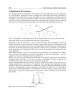
5.4 Instant Center, Points of Zero Velocity 133
5.5 Illustrative Example: A Four-Bar Linkage 136
5.6 Chains of Bodies 142
5.7 Instant Center, Analytical Considerations 147
5.8 Instant Center of Zero Acceleration 150
Problems 156
Chapter 6
Forces and Force Systems 163
6.1 Introduction 163
6.2 Forces and Moments 163
6.3 Systems of Forces 165
6.4 Zero Force Systems 170
6.5 Couples 170
6.6 Wrenches 173
6.7 Physical Forces: Applied (Active) Forces 177
6.7.1 Gravitational Forces 177
6.7.2 Spring Forces 178
6.7.3 Contact Forces 180
6.7.4 Action–Reaction 181
6.8 First Moments 182
6.9 Physical Forces: Inertia (Passive) Forces 184
References 187
Problems 187
Chapter 7
Inertia, Second Moment Vectors, Moments and Products of Inertia,
Inertia Dyadics 199
7.1 Introduction 199
7.2 Second-Moment Vectors 199
0593_ FM_fm Page 12 Tuesday, May 14, 2002 10:19 AM
7.3 Moments and Products of Inertia 200
7.4 Inertia Dyadics 203
7.5 Transformation Rules 205
7.6 Parallel Axis Theorems 206
7.7 Principal Axes, Principal Moments of Inertia: Concepts 208
7.8 Principal Axes, Principal Moments of Inertia: Example 211
7.9 Principal Axes, Principal Moments of Inertia: Discussion 215
7.10 Maximum and Minimum Moments and Products of Inertia 223
7.11 Inertia Ellipsoid 228
7.12 Application: Inertia Torques 228
References 230
Problems 230
Chapter 8
Principles of Dynamics: Newton’s Laws and d’Alembert’s Principle 241
8.1 Introduction 241
8.2 Principles of Dynamics 242
8.3 d’Alembert’s Principle 243
8.4 The Simple Pendulum 245
8.5 A Smooth Particle Moving Inside a Vertical Rotating Tube 246
8.6 Inertia Forces on a Rigid Body 249
8.7 Projectile Motion 251
8.8 A Rotating Circular Disk 253
8.9 The Rod Pendulum 255
8.10 Double-Rod Pendulum 258
8.11 The Triple-Rod and
N
-Rod Pendulums 260
8.12 A Rotating Pinned Rod 263
8.13 The Rolling Circular Disk 267
8.14 Closure 270
References 270
Problems 271
Chapter 9
Principles of Impulse and Momentum 279
9.1 Introduction 279
9.2 Impulse 279
9.3 Linear Momentum 280
9.4 Angular Momentum 282
9.5 Principle of Linear Impulse and Momentum 285
9.6 Principle of Angular Impulse and Momentum 288
9.7 Conservation of Momentum Principles 294
9.8 Examples 295
9.9 Additional Examples: Conservation of Momentum 301
9.10 Impact: Coefficient of Restitution 303
9.11 Oblique Impact 306
9.12 Seizure of a Spinning, Diagonally Supported, Square Plate 309
9.13 Closure 310
Problems 311
Chapter 10
Introduction to Energy Methods 321
10.1 Introduction 321
10.2 Work 321
10.3 Work Done by a
Couple 326
0593_ FM_fm Page 13 Tuesday, May 14, 2002 10:19 AM
10.4 Power 327
10.5 Kinetic Energy 327
10.6 Work–Energy Principles 329
10.7 Elementary Example: A Falling Object 332
10.8 Elementary Example: The Simple Pendulum 333
10.9 Elementary Example — A Mass–Spring System 336
10.10 Skidding Vehicle Speeds: Accident Reconstruction Analysis 338
10.11 A Wheel Rolling Over a Step 341
10.12 The Spinning Diagonally Supported Square Plate 342
10.13 Closure 344
References (Accident Reconstruction) 344
Problems 344
Chapter 11
Generalized Dynamics: Kinematics and Kinetics 353
11.1 Introduction 353
11.2 Coordinates, Constraints, and Degrees of Freedom 353
11.3 Holonomic and Nonholonomic Constraints 357
11.4 Vector Functions, Partial Velocity, and Partial Angular Velocity 359
11.5 Generalized Forces: Applied (Active) Forces 363
11.6 Generalized Forces: Gravity and Spring Forces 367
11.7 Example: Spring-Supported Particles in a Rotating Tube 369
11.8 Forces That Do Not Contribute to the Generalized Forces 375
11.9 Generalized Forces: Inertia (Passive) Forces 377
11.10 Examples 379
11.11 Potential Energy 389
11.12 Use of Kinetic Energy to
Obtain Generalized Inertia Forces 394
11.13 Closure 401
References 401
Problems 402
Chapter 12
Generalized Dynamics: Kane’s Equations
and Lagrange’s Equations 415
12.1 Introduction 415
12.2 Kane’s Equations 415
12.3 Lagrange’s Equations 423
12.4 The Triple-Rod Pendulum 429
12.5 The
N
-Rod Pendulum 433
12.6 Closure 435
References 436
Problems 436
Chapter 13
Introduction to Vibrations 439
13.1 Introduction 439
13.2 Solutions of Second-Order Differential Equations 439
13.3 The Undamped Linear Oscillator 444
13.4 Forced Vibration of an Undamped Oscillator 446
13.5 Damped Linear Oscillator 447
13.6 Forced Vibration of a Damped Linear Oscillator 449
13.7 Systems with Several Degrees of Freedom 450
13.8 Analysis and Discussion of Three-Particle Movement:
Modes of Vibration 455
0593_ FM_fm Page 14 Tuesday, May 14, 2002 10:19 AM
13.9 Nonlinear Vibrations 458
13.10 The Method of Krylov and Bogoliuboff 463
13.11 Closure 466
References 466
Problems 467
Chapter 14
Stability 479
14.1 Introduction 479
14.2 Infinitesimal Stability 479
14.3 A Particle Moving in a Vertical Rotating Tube 482
14.4 A Freely Rotating Body 485
14.5 The Rolling/Pivoting Circular Disk 488
14.6 Pivoting Disk with a Concentrated Mass on the Rim 493
14.6.1 Rim Mass in the Uppermost Position 498
14.6.2 Rim Mass in the Lowermost Position 502
14.7 Discussion: Routh–Hurwitz Criteria 505
14.8 Closure 509
References 509
Problems 510
Chapter 15
Balancing 513
15.1 Introduction 513
15.2 Static Balancing 513
15.3 Dynamic Balancing: A Rotating Shaft 514
15.4 Dynamic Balancing: The General Case 516
15.5 Application: Balancing of Reciprocating Machines 520
15.6 Lanchester Balancing Mechanism 525
15.7 Balancing of Multicylinder Engines 526
15.8 Four-Stroke Cycle Engines 528
15.9 Balancing of Four-Cylinder Engines 529
15.10 Eight-Cylinder Engines: The Straight-Eight and the V-8 532
15.11 Closure 534
References 534
Problems 534
Chapter 16
Mechanical Components: Cams 539
16.1 Introduction 539
16.2 A Survey of Cam Pair Types 540
16.3 Nomenclature and Terminology for Typical Rotating Radial Cams
with Translating Followers 541
16.4 Graphical Constructions: The Follower Rise Function 543
16.5 Graphical Constructions: Cam Profiles 544
16.6 Graphical Construction: Effects of Cam–Follower Design 545
16.7 Comments on Graphical Construction of Cam Profiles 549
16.8 Analytical Construction of Cam Profiles 550
16.9 Dwell and Linear Rise of the Follower 551
16.10 Use of Singularity Functions 553
16.11 Parabolic Rise Function 557
16.12 Sinusoidal Rise Function 560
16.13 Cycloidal Rise Function 563
16.14 Summary: Listing of Follower Rise Functions 566
0593_ FM_fm Page 15 Tuesday, May 14, 2002 10:19 AM
16.15 Closure 568
References 568
Problems 569
Chapter 17
Mechanical Components: Gears 573
17.1 Introduction 573
17.2 Preliminary and Fundamental Concepts: Rolling Wheels 573
17.3 Preliminary and Fundamental Concepts: Conjugate Action 575
17.4 Preliminary and Fundamental Concepts: Involute Curve Geometry 578
17.5 Spur Gear Nomenclature 581
17.6 Kinematics of Meshing Involute Spur Gear Teeth 584
17.7 Kinetics of Meshing Involute Spur Gear Teeth 588
17.8 Sliding and Rubbing between Contacting Involute Spur Gear Teeth 589
17.9 Involute Rack 591
17.10 Gear Drives and Gear Trains 592
17.11 Helical, Bevel, Spiral Bevel, and Worm Gears 595
17.12 Helical Gears 595
17.13 Bevel Gears 596
17.14 Hypoid and Worm Gears 597
17.15 Closure 599
17.16 Glossary of Gearing Terms 599
References 601
Problems 602
Chapter 18
Introduction to Multibody Dynamics 605
18.1 Introduction 605
18.2 Connection Configuration: Lower Body Arrays 605
18.3 A Pair of Typical Adjoining Bodies: Transformation Matrices 609
18.4 Transformation Matrix Derivatives 612
18.5 Euler Parameters 613
18.6 Rotation Dyadics 617
18.7 Transformation Matrices, Angular Velocity Components,
and Euler Parameters 623
18.8 Degrees of Freedom, Coordinates, and Generalized Speeds 628
18.9 Transformations between Absolute and Relative Coordinates 632
18.10 Angular Velocity 635
18.11 Angular Acceleration 640
18.12 Joint and Mass Center Positions 643
18.13 Mass Center Velocities 645
18.14 Mass Center Accelerations 647
18.15 Kinetics: Applied (Active) Forces 647
18.16 Kinetics: Inertia (Passive) Forces 648
18.17 Multibody Dynamics 650
18.18 Closure 651
References 651
Problems 652
Chapter 19
Introduction to Robot Dynamics 661
19.1 Introduction 661
19.2 Geometry, Configuration, and Degrees of Freedom 661
19.3 Transformation Matrices and Configuration Graphs 663
0593_ FM_fm Page 16 Tuesday, May 14, 2002 10:19 AM
19.4 Angular Velocity of Robot Links 665
19.5 Partial Angular Velocities 667
19.6 Transformation Matrix Derivatives 668
19.7 Angular Acceleration of the Robot Links 668
19.8 Joint and Mass Center Position 669
19.9 Mass Center Velocities 671
19.10 Mass Center Partial Velocities 673
19.11 Mass Center Accelerations 673
19.12 End Effector Kinematics 674
19.13 Kinetics: Applied (Active) Forces 677
19.14 Kinetics: Passive (Inertia) Forces 680
19.15 Dynamics: Equations of Motion 681
19.16 Redundant Robots 682
19.17 Constraint Equations and Constraint Forces 684
19.18 Governing Equation Reduction and Solution: Use of Orthogonal
Complement Arrays 687
19.19 Discussion, Concluding Remarks, and Closure 689
References 691
Problems 691
Chapter 20
Application with Biosystems, Human Body Dynamics 701
20.1 Introduction 701
20.2 Human Body Modeling 702
20.3 A Whole-Body Model: Preliminary Considerations 703
20.4 Kinematics: Coordinates 706
20.5 Kinematics: Velocities and Acceleration 709
20.6 Kinetics: Active Forces 715
20.7 Kinetics: Muscle and Joint Forces 716
20.8 Kinetics: Inertia Forces 719
20.9 Dynamics: Equations of Motion 721
20.10 Constrained Motion 722
20.11 Solutions of the Governing Equations 724
20.12 Discussion: Application and Future Development 727
References 730
Problems 731
Appendix I
Centroid and Mass Center Location for Commonly Shaped Bodies
with Uniform Mass Distribution 735
Appendix II
Inertia Properties (Moments and Products of Inertia)
for Commonly Shaped Bodies with Uniform Mass Distribution 743
Index
753
0593_ FM_fm Page 17 Tuesday, May 14, 2002 10:52 AM
0593_ FM_fm Page 18 Tuesday, May 14, 2002 10:19 AM
1
1
Introduction
1.1 Approach to the Subject
This book presents an introduction to the dynamics of mechanical systems; it is based
upon the principles of elementary mechanics. Although the book is intended to be self-
contained, with minimal prerequisites, readers are assumed to have a working knowledge
of fundamental mechanics’ principles and a familiarity with vector and matrix methods.
The readers are also assumed to have knowledge of elementary physics and calculus. In
this introductory chapter, we will review some basic assumptions and axioms and other
preliminary considerations. We will also begin a review of vector methods, which we will
continue and expand in Chapter 2.
Our procedure throughout the book will be to develop a general methodology which
we will then simplify and specialize to topics of interest. We will attempt to illustrate
the concepts through examples and exercise problems. The reader is encouraged to solve
as many problems as possible. Indeed, it is our belief that a basic understanding of the
concepts and an intuitive grasp of the subject are best obtained through solving the
exercise problems.
1.2 Subject Matter
Dynamics is a subject in the general field of mechanics, which in turn is a discipline of
classical physics. Mechanics can be divided into two divisions: solid mechanics and fluid
mechanics. Solid mechanics may be further divided into flexible mechanics and rigid
mechanics. Flexible mechanics includes such subjects as strength of materials, elasticity,
viscoelasticity, plasticity, and continuum mechanics. Alternatively, aside from statics,
dynamics is the essence of rigid mechanics. Figure 1.2.1 contains a chart showing these
subjects and their relations to one another.
Statics
is a study of the behavior of rigid body systems when there is no motion. Statics
is concerned primarily with the analysis of forces and force systems and the determination
of equilibrium configurations. In contrast,
dynamics
is a study of the behavior of moving
rigid body systems. As seen in Figure 1.2.1, dynamics may be subdivided into three sub-
subjects: kinematics, inertia, and kinetics.
0593_C01_fm Page 1 Monday, May 6, 2002 1:43 PM
2
Dynamics of Mechanical Systems
Kinematics
is a study of motion without
regard to the cause of the motion. Kine-
matics includes an analysis of the posi-
tions, displacements, trajectories,
velocities, and accelerations of the mem-
bers of the system.
Inertia
is a study of the
mass properties of the bodies of a system
and of the system as a whole in various
configurations.
Kinetics
is a study of forces.
Forces are generally divided into two
classes:
applied
(or “active”) forces and
iner-
tia
(or “passive”) forces. Applied forces
arise from contact between bodies and
from gravity; inertia forces occur due to the
motion of the system.
1.3 Fundamental Concepts and Assumptions
The study of dynamics is based upon several fundamental concepts and basic assumptions
that are intuitive and based upon common experience: time, space, force, and mass.
Time
is a measure of change or a measure of a process of events; in dynamics, time is assumed
to be a continually increasing, non-negative quantity.
Space
is a geometric region where
events occur; in the study of dynamics, space is usually defined by reference frames or
coordinate systems.
Force
is intuitively described as a push or a pull. The effect of a force
depends upon the magnitude, direction, and point of application of the push or pull; a
force is thus ideally suited for representation by a vector.
Mass
is a measure of inertia
representing a resistance to change in motion; mass is the source of gravitational attraction
and thus also the source of weight forces.
In our study we will assume the existence of an
inertial reference frame
, which is simply
a reference frame where Newton’s laws are valid. More specifically, we will assume the
Earth to be an inertial reference frame for the range of systems and problems considered
in this book.
Newton’s laws may be briefly stated as follows:
1. In the absence of applied forces, a particle at rest remains at rest and a particle
in motion remains in motion, moving at a constant speed along a straight line.
2. A particle subjected to an applied force will accelerate in the direction of the
force, and the acceleration will be proportional to the magnitude of the force
and inversely proportional to the mass of the particle. Analytically, this may be
expressed as
(1.3.1)
where
F
is the force (a vector),
m
is the particle mass, and
a
is the resulting
acceleration (also a vector).
3. Within a mechanical system, interactive forces occur in pairs with equal magni-
tudes but opposite directions (the law of action and reaction).
Fa= m
FIGURE 1.2.1
Subdivisions of mechanics.
0593_C01_fm Page 2 Monday, May 6, 2002 1:43 PM
Introduction
3
1.4 Basic Terminology in Mechanical Systems
Particular terminology is associated with dynamics, and specifically with mechanical
system dynamics, which we will use in the text. We will attempt to define the terms as
we need them, but it might also be helpful to mention some of them here:
• A
space
is a region or geometric entity occupied by particles where, for our
purposes, dynamic events will occur.
• A
reference frame
may be regarded as a coordinate axis system containing and
locating the points of a space. Typical reference frames employ Cartesian axes
systems.
• A
particle
is a small body whose dimensions are either negligible or irrelevant
in the description of its motion and of its response to forces applied to it. “Small”
is, of course, a relative term. A body considered as a particle may be small in
some contexts but not in others (for example, an Earth satellite or an automobile).
Particles are generally identified with points in space, and they generally have
finite masses.
• A
rigid body
is a set of particles whose distances from one another remain fixed,
or constant, such as a sandstone. The number of particles in a body is usually
quite large. A reference frame may be regarded, for kinematic purposes, as a
rigid body whose particles have zero masses.
• A
degree of freedom
is defined as a way in which a particle, body, or system can
move. The number of degrees of freedom possessed by a particle, body, or system
is defined as the number of geometric parameters (for example, coordinates,
distances, or angles) needed to uniquely describe the location, orientation, and/
or configuration of the particle, body, or system.
• A
constraint
is a restriction on the motion of a particle, body, or system. Con-
straints can be either geometric (holonomic) or kinematic (nonholonomic).
• A
machine
is an arrangement of a system of bodies designed for applying, trans-
mitting, and/or changing forces and motion.
• A
mechanism
is a machine intended primarily for the transmission of motion.
The three general categories of machines are:
1.
Gear systems
, which are toothed bodies in contact whose objectives are to
transmit motion between rotating shafts.
2.
Cam systems
, which are bodies with curved profiles in contact whose objec-
tives are to transmit motion between a rotating member and a nonrotating
member. The term “cam” is sometimes also used to describe a gear tooth.
3.
Linkages
, which are multibody systems intended to provide either a desired
motion of a rigid body or the motion of a point of a body along a curve.
• A
link
is a connective member of a machine or a mechanism. A link maintains
a constant distance between two points of a mechanism, although links may be
one way, such as cables.
• A
driver
is an “input” link that stimulates a motion.
• A
follower
is an “output” link that responds to the input stimulus of the driver.
0593_C01_fm Page 3 Monday, May 6, 2002 1:43 PM
4
Dynamics of Mechanical Systems
• A
joint
is a connective member of a mechanism, usually bringing together two
elements of a mechanism. Two elements brought together by a joint are some-
times called
kinematic pairs
. Figure 1.4.1 shows a number of commonly used joints
(or kinematic pairs).
• A
kinematic chain
is a series of links that are either joined together or are in contact
with one another. A kinematic chain may contain one or more loops. A loop is
a chain whose ends are connected. An
open chain
(or “open tree”) contains no
loops, a
simple chain
contains one loop, and a
complex chain
involves more than
one loop or one loop with open branches.
Joint Name
Schematic
Representation
Degrees
of Freedom
Revolute (pin) 1
Prismatic (slider) 1
Helix (screw) 1
Cylinder (sliding pin) 2
Spherical (ball and socket) 3
Planar 2
Universal (hook) 2
Spur gear (rollers) 1
Cam 1
FIGURE 1.4.1
Commonly used joints and kinematics pairs.
0593_C01_fm Page 4 Monday, May 6, 2002 1:43 PM
Introduction
5
1.5 Vector Review
Because vectors are used extensively in the text,
it is helpful to review a few of their fundamental
concepts. We will expand this review in Chapter
2. Mathematically, a vector may be defined as an
element of a vector space (see, for example, Ref-
erences 1.1 to 1.3). For our purposes, we may think
of a vector simply as a directed line segment.
Figure 1.5.1 shows some examples of vectors
as directed line segments. In this context, vectors
are seen to have several characteristics: magni-
tude, orientation, and sense. The
magnitude
of a
vector is simply its length; hence, in a graphical
representation as in Figure 1.5.1, the magnitude
is simply the geometrical length. (Observe, for example, that vector
2B
has a length and
magnitude twice that of vector
B
.) The
orientation
of a vector refers to its inclination in
space; this inclination is usually measured relative to some fixed coordinate system. The
sense
of a vector is designated by the position of the arrowhead in the geometrical repre-
sentation. Observe, for example, in Figure 1.5.1 that vectors
A
and –
A
have opposite sense.
The combined characteristics of orientation and sense are sometimes called the
direction
of a vector.
In this book, we will use vectors to represent forces, velocities, and accelerations. We
will also use them to locate points and to indicate directions. The units of a vector are
those of its magnitude. In turn, the units of the magnitude depend upon the quantity the
vector represents. For example, if a vector represents a force, its magnitude is measured
in force units such as Newtons (N) or pounds (lb). Alternatively, if a vector represents
velocity, its units might be meters per second (m/sec) or feet per second (ft/sec). Hence,
vectors representing different quantities will have graphical representations with different
length scales. (A review of specific systems of units is presented in Section 1.7.)
Because vectors have the characteristics of magnitude and direction they are distinct
from scalars, which are simply elements of a real or complex number system. For example,
the magnitude of a vector is a scalar; the direction of a vector is not a scalar. To distinguish
vectors from scalars, vectors are printed in bold-face type, such as
V
. Also, because the
magnitude of a vector is never negative (length is
never negative), absolute-value signs are used to
designate the magnitude, such as
V
.
In the next chapter, we will review algebraic oper-
ations of vectors, such as the addition and multipli-
cation of vectors. In preparation for this, it is helpful
to review the concept of multiplication of vectors by
scalars. Specifically, if a vector
V
is multiplied by a
scalar
s
, the product, written as
s
V
, is a vector whose
magnitude is
s
V
, where
s
is the absolute
value of the scalar
s
. The direction of
s
V
is the same
as that of
V
if
s
is positive and opposite that of
V
if
s
is negative. Figure 1.5.2 shows some examples of
products of scalars and vectors.
FIGURE 1.5.1
Vectors depicted as directed line segments.
A
B
-A
2B
FIGURE 1.5.2
Examples of products of scalars and a
vector
V
.
V
2V
(1/2)V
-(3/2)V
0593_C01_fm Page 5 Monday, May 6, 2002 1:43 PM
6
Dynamics of Mechanical Systems
Two kinds of vectors occur so frequently that they deserve special attention: zero vectors
and unit vectors. A
zero vector
is simply a vector with magnitude zero. A
unit vector
is a
vector with magnitude one; unit vectors have no dimensions or units.
Zero vectors are useful in equations involving vectors. Unit vectors are useful for
separating the characteristics of vectors. That is, every vector
V
may be expressed as the
product of a scalar and a unit vector. In such a product, the scalar represents the magnitude
of the vector and the unit vector represents the direction. Specifically, if
V
is written as:
(1.5.1)
where
s
is a scalar and
n
is a unit vector, then
s
and
n
are:
(1.5.2)
This means that given any non-zero vector
V
we can always find a unit vector
n
with the
same direction as V; thus,
n
represents the direction of
V
.
1.6 Reference Frames and Coordinate Systems
We can represent a reference frame by identifying it with a coordinate–axes system such
as a Cartesian coordinate system. Specifically, we have three mutually perpendicular lines,
called
axes
, which intersect at a point
O
called the
origin
, as in Figure 1.6.1. The space is
then filled with “points” that are located relative to
O
by distances from
O
to
P
measured
along lines parallel to the axes. These distances form sets of three numbers, called the
coordinates
of the points. Each point is then associated with its coordinates.
The points in space may also be located relative to
O
by introducing additional lines
conveniently associated with the points together with the angles these lines make with
the mutually perpendicular axes. The coordinates of the points may then involve these
angles.
To illustrate these concepts, consider first the Cartesian coordinate system shown in
Figure 1.6.2, where the axes are called
X
,
Y
, and
Z
. Let
P
be a typical point in space. Then
the coordinates of
P
are the distances
x
,
y
, and
z
from
P
to the planes
Y–Z
,
Z–X
, and
X–Y
,
respectively.
FIGURE 1.6.1
A reference frame with origin
O
.
FIGURE 1.6.2
Cartesian coordinate system.
Vn= s
s ==VnVVand /
O
O
Z
Y
X
P(x,y,z)
0593_C01_fm Page 6 Monday, May 6, 2002 1:43 PM