Advances in Human Robot Interaction Part 2 ppsx
Bạn đang xem bản rút gọn của tài liệu. Xem và tải ngay bản đầy đủ của tài liệu tại đây (1.11 MB, 25 trang )
Advances in Human-Robot Interaction
14
Simultaneous localization and mapping (SLAM) is another feature we wish to discuss here.
Within this respect, robots are not only able to identify friends from foes but also they
construct a real-time map of the situation without use of expensive equipments as laser
beam sensors or vision cells.
There have been a lot of change and improvement in robotics within current decade. Today,
humanoid robots such as ASIMO are able to talk, walk, learn and communicate. On the
other hand, there are new trends for self-adjustment and calibration in wheeled robots. Both
humanoid and wheeled robots may be able to identify friends or foes, communicate with
others, and correct deviation errors. Researchers have provided quite acceptable balance
mechanisms for any type of inverted pendulum based robots from a range of humanoids
holding themselves on one leg to wheeled robots standing on a wheel or two while moving.
Yet they cannot jump, nor run on irregular surfaces like humans do. However, there are
many other features including speech synthesizing and video processing enabled on more
advanced robots.
Advanced robots should be equipped with further human-like capability to reason and base
it on knowing the meaning of its surroundings. At this point, we tend to introduce the
subject of Semantic Intelligence (SI) as opposed to and in augmentation of conventional
artificial intelligence. Better understanding of environment, and reasoning necessarily
through SI fueled by the intelligence of knowing the meaning of what goes around. In other
words, SI would be enabling robots with the power of imagination as we do. As future
study, we aim to shed some light on bases of robotic behavior towards thinking, learning,
and imagining the way human being does through Semantic Intelligence Reasoning.
In next section, we will discuss self localization of robots with limited resources while they
have neither shaft encoders nor gyroscope. Consequent section will represent more
advanced family of robots where they are able to correct deviated errors with use of
gyroscope, accelerometer, and shaft encoder in a triple cascaded loop. Section 4 presents our
formulations and algorithms for identification of Friend or Foe and responding accordingly
in battle of multi and collaborative robots. Then we will present Simultaneous Localization
and Mapping for multi collaborative robots in section 5. Section 6 will cover a brief
introductory on Semantic Intelligence and application example for solving a robotic
problem. Finally the chapter is concluded in section 7.
2. Through-cell self-localization
Line following is one of the simplest categories of wheeled robots. Line following robots is
mainly equipped with two DC motors for left and right wheels and line tracking sensors
which is a set of 1 to 6 Infrared transceiver pairs. (Notice that using only one sensor to
follow a line makes the robot able to only follow edge of a connected and simple path
without extra loops). Microrobot Cruiser robot (Active-Robots) were selected for this section
due to the simplicity of design. In addition, there is neither shaft encoder nor gyroscope on
this robot. It is aimed to enable even such robots to traverse the desired curve or path.
As can be seen in Fig. 1 (A), the front side of the robot is equipped with 6 IR sensors (3 at left
and at right side) each one consisting of an infrared transmitter LED and an infrared
receiver transistor read by ADC port of the microcontroller. The ADC port output is a
voltage between [0,V
max
] presenting the reverse relation with distance to reflector (an
obstacle, for example, walls in labyrinth platform). Sensors provide
approximately
when the robot so close as to touch a wall. Initial calibration may be performed by keeping
Towards Semantically Intelligent Robots
15
the sensors as close as possible to reflector and then recording the captured voltage. The
output of 6 sensors is presented by the
,
,
,
,
,
tuples where subscripts l and
r are respectively for sensors placed at left and right side of the robot. F is for front sensor, S
shows side sensor and finally B indicates the sensors installed to watch 45° towards
backside of the robot on both sides (i.e. S
l
is the voltage level of left side IR sensor). When a
robot is in the center of a cell with approximately same distance from either side walls, we
end up with
s.t.
0,
. Notice that
stands for maximum voltage
captured from sensors and let’s assume that
represents the maximum velocity of
motors.
Fig. 1. left section of sensor boards of Microrobot Cruiser robot (A), and Turning left over
the perimeter of the circle in a labyrinth: representation of a situation where the decision
maker has decreed that the robot is to turn left (B).
For a robot turning toward a direction, its starting position is important. The radius of the
curve and its length need be calculated. The main points are deciding on which curve
(radius defines it) is the best choice, and when the turn has been accomplished. It is assumed
that the best curve is the one which keeps the robot straddling the middle line of the next
cell.
Practically, if
, where is a small threshold value and
,
then the robot continues moving straight so that
0 or
0
(depending on the direction of turn) until
or
. It indicates that the
center of axes of wheels is approximately on
,
. Now on the robot can start turning
over the desired curve with defined radius. Therefore, it traverses a quarter of perimeter of
the circle with radius r
in which its initial point is
,
and its destination
point is
,
. Notice that x is the thickness of a wall and d is the distance between two
walls or the cell width. We assume that
,
0,0
as initial point befor turning and
,
,
is the point after turning left, whereas
,
would be
,
for turning
right. As a result, traversed distance over the perimeter of inner and outer curves is
calculated by the following formula (1). Additionally, we require adjusting the speed of
motors as shown in (2); it’s clear that the robot does not need shaft encoders in order to
measure the traversed distance. Turning is continued until
(for turning left) or
(while turning right).
x
,
,
,
F
l
S
l
B
l
45
̊
(A)
(B)
Advances in Human-Robot Interaction
16
TurningLeft:
2π
2
,
2π
2
Turning Right:
2π
2
,
2π
2
(1)
TurningLeft:
,
Turning Right:
,
(2)
Now let’s consider more advanced robots which are widely used in real-life where not only
pushing the robot to follow a specific curve is intended but also error detection and
correction is considered simultaneously. Autonomous Guided Vehicles (AGVs) are highly
used everywhere. Next section presents a solution to error detection and correction in
situations that the machine works properly however, problems such as slippage causes
deviation.
3. Self-corrective cascaded control
Self-corrective gyroscope-accelerometer-encoder cascade control system adjusts the robot if
the host vehicle deviates from its designated lane. In case the vehicle detects that it has
yawed away, the system calculates a desired maneuvering moment in order to correct
deviation. The calculation is simply addition/subtraction from the desired value of
movement expected from shaft encoder sensors of both wheels. This is done by steering the
host vehicle back on course in a direction that avoids the host vehicle's lane deviation. The
system compensates for the desired yawing moment by a correction factor or a gain.
Manufacturing a new generation of AGVs with ability of self-corrective gyroscope-
accelerometer-encoder cascade control system will improve current AGVs and cooperative
robots to overcome their major difficulties and improve their utility.
When measuring odometry errors, one must distinguish between 1) Systematic errors and
2) non-systematic errors. Systematic errors are caused by kinematic imperfections of the
mobile robot (i.e. unequal wheel-diameters). Another systematic error caused in many
researches is simplifying kinematic control properties by default values (i.e. d = 0, d is
distance from new referenced point to intersection of rear wheel axis and symmetry axis of
mobile robot). Extending the kinematic control into dynamics level, the majority of
researchers consider the general case of d = 0 in dynamic model of mobile robot, whereas the
restriction of I = 0 is mostly imposed by the kinematic controller (Pengcheng & Zhicheng,
2007). On the other hand, non-systematic errors may be caused by wheel-slippage or
irregularities of the floor. University of Michigan Benchmark test (UMBmark), is a test
method for systematic errors prescribing a simple testing procedure designed to
quantitatively measure the odometric accuracy of a mobile robot (Borenstein & Feng, 1995).
Non-systematic errors are more difficult to be detected. Cascade control systems for
localization are more reliable in this sense.
J. Borenstein et al (Borenstein et al., 1997) defined seven categories for positioning systems
based on the type of sensors used in controlling the robot. 1) Odometry is based on simple
Towards Semantically Intelligent Robots
17
equations which hold true when wheel revolutions can be translated accurately into linear
displacement relative to the floor. However, in case of wheel slippage and some other more
subtle causes, wheel rotations may not translate proportionally into linear motion. The
resulting errors can be categorized into one of two groups: systematic errors and non-
systematic errors. 2) Inertial Navigation uses gyroscopes and accelerometers to measure
rate of rotation and acceleration, respectively. Measurements are integrated once (or twice,
for accelerometers) to yield position. 3) Magnetic Compass is widely used. However, the
earth's magnetic field is often distorted near power lines or steel structures. Besides, the
speed of measurement and accuracy is low. There are several types of magnetic compasses
due to variety of physical effects related to the earth's magnetic field. Some of them include
Mechanical, Fluxgate, Hall-effect, Magnetoresistive, and Magnetoelastic compasses. 4)
Active Beacons navigation systems are the most common navigation aids on ships and
airplanes, as well as on commercial mobile robot systems. Two different types of active
beacon systems can be distinguished: trilateration that is the determination of a vehicle's
position based on distance measurements to known beacon sources; and triangulation,
which in this configuration there are three or more active transmitters mounted at known
locations. 5) Global Positioning System (GPS) is a revolutionary technology for outdoor
navigation. GPS was developed as a Joint Services Program by the Department of Defense.
However, GPS is not applicable in most of robotics fields due to two reasons, firstly,
unavailability of GPS signals indoor; and secondly, low accuracy in small prototype single
chip GPS receivers used in cellular phones and robot boards. 6) Landmark Navigation is
based on landmarks that are distinct features so a robot can recognize from its sensory
input. Landmarks can be geometric shapes (e.g., rectangles, lines, circles), and they may
include additional information (e.g., in the form of bar-codes). In general, landmarks have a
fixed and known position, relative to which a robot can localize itself. 7) Model Matching or
Map-based positioning, also known as map matching is a technique in which the robot uses
its sensors to create a map of its local environment. This local map is then compared to a
global map previously stored in memory. If a match is found, then the robot can compute its
actual position and orientation in the environment. Certainly there are lots of situations
where achieving global map is unfeasible or prohibited. Therefore, solutions based on
independent sensors carried on robots are more likely valued.
Some applications of cascade control can be seen in the research done by (Ke et al., 2004)
where cascade control strategy of robot subsystem has been applied instead of the widely
used single speed-feedback closed-loop control strategy. They provided the cascade control
system such that the outer loop is to regulate speed of the wheel; the inner loop is to adjust
the current passing through the DC-motor. By applying cascade control system to DC-
motor, the unexpected time-delay and inaccuracy can be reduced. The dynamic features of
robots motion and anti-interference of robots can be improved. At the same time, the
damage of current to DC-motor can be dropped and the life span of DC-motor can be
prolonged.
Various control strategies for mobile robot formations have been reported in the literature,
including behavior based methods, virtual structure techniques, and leader–follower
schemes (Defoort et al., 2008). Among them, the leader–follower approaches have been well
recognized and become the most popular approaches.
The basic idea of this scheme is that one robot is selected as leader and is responsible for
guiding the formation. The other robots, called followers, are required to track the position
Advances in Human-Robot Interaction
18
and orientation of the leader with some prescribed offsets. The advantage of using such a
strategy is that specifying a single quantity (the leader’s motion) directs the group behavior.
In followers, sliding-mode formation controller is applied which is only based on the
derivation of relative motion states. It eliminates the need for measurement or estimation of
the absolute velocity of the leader and enables formation control using vision systems
carried by the followers. However, it creates bottleneck for message passing and decision
making while it can be improved by decentralized autonomous control such as in (Elçi &
Rahnama, 2009) on the other hand, situations wherein the leader dies is not considered.
Other method of cascade control in robotics is with use of multi visual elements in
positioning and controlling the motion of articulated arms (Lippiello et al., 2007). In a multi
arm robotic cell, visual systems are usually composed of two or more cameras that can be
rigidly attached to the robot end-effectors or fixed in the workspace. Hence, the use of both
configurations at the same time makes the execution of complex tasks easier and offers
higher flexibility in the presence of a dynamic scenario.
Cascade control for positioning is also used in Unmanned Aerial Vehicles (UAVs). A
decentralized cascade control system including autopilot and trajectory control units
presents more precise collision avoidance strategy (Boivin et al., 2008).
3.1 Impact and significance of self-corrective AGVs in human life
Following information on various application areas of AGVs is presented in order to
highlight wide spectrum of applicability of the results of the upgraded AGVs.
3.1.1 AGVs for automobile manufacturing
Typical AGV applications in the automotive industry include automated raw material
delivery, automated work in process movements between manufacturing cells, and finished
goods transport. AGVs link shipping/receiving, warehousing, and production with just-in-
time part deliveries that minimize line side storage requirements. AGV systems help create
the fork-free manufacturing environment which many plants in the automotive industry are
seeking.
3.1.2 Hospitals
Using an AGV Automated Transport System (ATS) frees hospital employees to spend a
maximum amount of their time directly on patient care. It improves safety in the hospital
by minimizing the potential for hospital workers to be injured pushing heavy carts. It tracks
all material movements and can prioritize jobs so that the most important tasks can be
completed first (for example: surgical supplies, then patient meals, then linens, then trash,
etc.) The AGV can be outfitted with obstacle detection sensors which bring it to a safe stop
before contacting any obstacles that might be in its path. It is reliable, safe, efficient and
cost effective.
3.1.3 AGV (Automated Guided Vehicle) systems for the manufacturing industry
Timely movement of materials is a critical element to an efficient manufacturing operation.
The costs associated with delivering raw materials, moving work in process and removing
finished goods must be minimized while also minimizing any product damage that is the
result of improper handling. An AGV system helps streamline operations while also
delivering improved safety and tracking the movement of materials.
Towards Semantically Intelligent Robots
19
Our aim is to create a universal AGV controller board with the abilities as explained in the
previous section. Manufacturing a new generation of AGVs with ability of Self-Corrective
Compass Cascaded Control System will improve current AGVs to overcome difficulties
mentioned earlier.
The product is a universal robot controller board which can be produced and exported
worldwide. Future enhancements were taken into account as covering more servo/stepper
motors for full fledged robots serving different purposes.
3.2 Cascaded control method
AGVs are widely used in production lines of factories. They mostly track a line on floor
rather than being able to accurately follow dynamics of planned trajectories of start and end
positions. In more advanced cases, they are equipped with a feedback control loop, which
corrects the deviation errors due to movement imperfection of actuators and motors. This
section presents triple feedback loops consisting of gyroscope, accelerometer, and shaft-
encoder to provide self-corrective cascade control system.
A cascade control system is a multiple-loop system where the primary variable is controlled
by adjusting the set point of a related secondary variable controller. The secondary variable
then affects the primary variable through the process.
The primary objective in cascade control is to divide an otherwise difficult to control process
into two portions, whereby a secondary control loop is formed around major disturbances
thus leaving only minor disturbances to be controlled by the primary controller.
Despite the fact that first loop (which might be implemented by a PID controller) detects
and corrects deviation errors in trajectory planning, however in practice there are
disturbances that are generally excluded in theoretical implementations. Nevertheless,
disturbances such as friction and slippage are highly important and are frequently
happening in real life robotic implementations. For instance, an oily floor in factory causes
AGVs to slide however, the primary control does not recognize it.
In such a scenario, Global Positioning System (GPS) is not useful either because rotational
errors (without movement of the position) are not detectable. In addition, in real life
examples of factories, reading GPS signals indoor is barely possible. Besides, accuracy of
GPS receptors is very low in small form factor carried by tiny robots.
On the other hand, errors caused by skidding wheels while robot has not moved or parallel
deviation can be detected by a ternary control loop using not only detection of movement,
but also detection of acceleration towards each axis.
3.3 Feedback control mechanism:
Essentially the movement of the robot is translated in terms of number of Pulses generated
from shaft-encoders connected to each wheel. The number of Steps estimates the length of
movement and rotation of each wheel. However it might face with an error in movement.
Therefore, the robot is deviated from the straight line. Consequently, error on both motors at
the same time do not deviate the robot from the line but it causes less or more movement on
that line. Therefore, the trajectory planning of the robot movement is planned as a rectangle
starting from a vertex and return to the same after passing all four edges.
This path is divided into smaller sub paths based on number of traversed pulses. And at each,
the magnetic angle of the robot is read using the compass module. If the robot is deviated the
correct value for control algorithm is calculated to eliminate and minimize the total error.
Advances in Human-Robot Interaction
20
Fig. 2. Feedback control with shaft encoder (A), additional loop for gyroscope (B), and the
third loop for accelerometer (C).
As shown in Fig. 2(A), the robot is only based on shaft encoder and without Gyroscope to be
used in cascaded control as the second loop. The loop continues until the number of pulses
coming from shaft encoders reaches the required value. For instance, the command
go_forward(1 meter) will be translated as Right_Servo(CW, 1000); and Left_Servo(CCW,
1000) then the shaft encoder which triggers external interrupt routines for counting left and
right pulses. The encoder value will be increased at each interrupt call until it reaches the
maximum value (i.e. 1000 in above example). Then it sends a stop command to pulse
generator module at control unit to stop the corresponding motor.
Such system yet is vulnerable to errors caused by the environment such as slippage while
shaft encoders yet present correct movement. A command might be wasted at mechanics of
motor because of voltage loss etc. in Addition, the motor might work but the wheel does not
have enough friction with the floor to push the robot. Therefore, gyroscope enables the
robot to understand such deviations. Fig. 2 (B) presents the cascaded control with inclusion
of Gyroscope. Yet, slippages in the direction of movement while both wheels having same
Control Servo Driver Servo Motor
Comman
PWM
Pulses
Shaft Encoder
∑
(B)
Angle
Gyroscope
∑
Estimated
Control Servo Driver Servo Motor
Comman
PWM
Pulses
Shaft Encoder
∑
(A)
Estimated
Control Servo Driver Servo Motor
Comman
PWM
Pulses
Shaft Encoder
∑
(C)
Angle
Gyroscope
∑
Estimated
Acceleratio
Accelerometer
∑
Estimated
Towards Semantically Intelligent Robots
21
amount of error do not activate gyroscope. Our proposed way to detect such error is to
control acceleration continuously toward direction of movement. Acceleration is zero while
traversing a path on a fixed speed. Moreover, acceleration can be subtracted from output of
accelerometer in situations that robot traverses a path on variable speed. Fig. 2 (C) presents
the triple cascade control loop.
3.3 Practical results
In order to test the result, we developed a scenario for movement of the robot without/with
triple cascade control feedback mechanism. The robot must traverse a rectangle of edge size
equal to one meter and return to the home position. The error is calculated in both
unmodified and modified robot assuming only one direction of rotation (CCW). Following
figure presents the developed scenario.
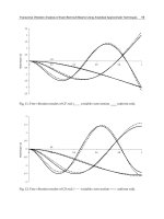
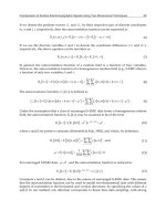
Fig. 3. Trajectory design of self-corrective cascade control robot
As shown in Fig. 4 (A), robot without second and third loop in cascade control mechanism
deviates a lot from desired positions in robot trajectory. Fig. 4 (B) presents the corrected
error after applying above mentioned loops to correct the deviation error.
Fig. 4. Robot with only shaft encoder feedback control loop (A), and results while triple loop
cascade control is applied (B).
Advances in Human-Robot Interaction
22
In next section more sophisticated robots are presented while they are not only to correct the
deviated errors but also they are able to identify friends from enemies in cooperative
environment and help each other towards achieving the common goal.
4. Friend-or-Foe identification
In this section a novel and simple-to-implement FOF identification system is proposed. The
system is composed of ultrasonic range finder rotary radar scanning the circumference for
obstacles, and an infrared receiver reading encrypted echo messages propagated from
omnidirectional infrared transmitter on the detected object through a fixed direction.
Each robot continuously transmits a message encrypted by a shared secret key between
teammates consisting of its unique identifier and timestamp. The simplicity is due to
excluding transceiver system for exchanging encoded/decoded messages. System counters
replay attack by comparing the sequence of decoded timestamp. Encryption is done using a
symmetric encryption technique such as RC5. The reason for selecting RC5 is its simplicity
and low decryption time. Besides its hardware implementation consists of few XOR and
simple basic operators which are available in all microcontrollers.
The decision making algorithm and behavioral aspects of each robot are represented as
follows.
1. Scan surrounding objects using ultrasonic sensor.
2. Create a record consist of distance and position for detected elements.
3. Fetch the queue top record and direct the rotary radar towards its position.
4. Listen to IR receptor within a certain period (i.e. 100 ms)
5. if no message is received
a. Clear all records
b. Attack the object
c. Go to 1
6. Otherwise,
a. Decode the message using the secret key
b. If not decodable Go to 5.a
c. Otherwise, register the identifier and timestamp besides position and distance for detected
object
d. Listen again to IR receptor within a certain period
e. Decode the message using the secret key
f. If not decodable Go to 5.a
g. Otherwise, match the identifier and timestamp against the one kept before
h. If identifier mismatches or timestamp is the same or smaller than as it was before, Go to 5.a
i. Else if detected identifier is the same as the identifier of detector, Go to 5.a
j. Go to 3
It is assumed that the received message is free of noise and corrupted messages are
automatically discarded. This can be done by listening for a limited number of times if
message is not decodable. However, transmission is modulated on a 38 KHz IR carrier so
sunlight and fluorescent light are not highly distorting the IR transmitted stream.
Towards Semantically Intelligent Robots
23
4.1 Hardware Implementation
Our first generation of cooperative mini sumo robot included an electronic compass instead
of gyroscope and accelerometer so it was not able to detect skidding errors towards any axes
without possibly the robot being rotated. Very common instance is when the robot is
pushed by enemies. Fig. 5 (A) presents the first developed board being able to control two
DC servomotors, communicate through wireless over 900MHz modulation, and having
infrared sensors and bumpers to detect surrounding objects.
In the second design, an extension board suitable for open source Mark III mini sumo robots is
presented. The Mark III Robot is the successor to the two previous robot kits designed and
sold by the Portland Area Robotics Society. The base robot is serial port programmable. It
includes PIC16F877 20MHz microcontroller with boot-loader which has made programming
steps easier. In System Programming (ISP) is provided by boot-loader facility. It is possible to
program the robot in Object Oriented PIC (OOPIC) framework. It includes controller for two
DC servomotors in addition to three line following and two range finder sensors. Low-battery
indicator is an extra feature provided on Mark III. However, there were few requirements to
enhance the robot to fit our requirements for cooperative robotics. Wireless Communication,
Ultrasonic range finder, infrared modulated transceiver, gyroscope, and acceleration sensors
were added in extension board as shown in fig. 5 (B). In addition, the robot uses two GWS
S03N 2BB DC servomotors each providing 70 gr.cm torques at 6v. However, the battery pack
connected to motors is not regulated so it does not provide steady voltage while discharging. It
effects center point of Servo calibration which effects servo proper movement. In extension
board, a regulator is also included to fix the problem explained above.
Such robots are able to communicate and collaborate with each other in addition to
benefitting from self-corrective cascaded control system. It can be easily used as a controller
for intelligent robotics to solve a given task cooperatively by multiple robots.
Fig. 5. The first generation of cooperative mini sumo platform robots 9×10 cm (A), and the
extension board for Mark III (B).
4.2 Cipher analysis and attacking strategies
Following figure represents two of the worst cases for decision making in battlefield. These
two crucial situations shown in Fig .6 includes 1) When an enemy robot masks a
Advances in Human-Robot Interaction
24
friend and enemy copies messages it receives from the masked friend to others so called
reply attack. 2) Attacking an enemy by two robots from opposite sides
Fig. 6. An example arrangement of two teams of robots while fighting. Arrows demonstrate
detection of objects.
4.2.1 Replay attack
In the first instance, E
1
stands between F
2
and F
3
covering their line of sight, so it is possible for
E
1
to copy messages propagated from F
3
and replay them to F
2
and present itself as a friend
and then attack against F
2
. In this situation, F
2
assumes that E
1
is friend F
3
and it will be
targeting the next possible enemy detected by rotary radar however it will be attacked by E
1
.
Part 6.1 of the algorithm presented in Section 2 counters replay attack. In order to avoid
replay attack, the timestamp included in decrypted message is compared against the one
received in advance. Besides, the other friend robot receives the same copy of its own
transmitted message including its identifier. Therefore it recognizes the enemy by matching
and comparing the identifier of copied message with its own unique identifier. Therefore it
recognizes the enemy.
4.2.2 Opposite side dual attack
According to the algorithm represented in previous section, both F
2
and F
3
start attacking E
1
from opposite sides either towards sideways of E
1
,
or one faces front of E
1
. In both cases,
they keep pushing enemy until they see the boundary so they return and start searching for
other enemies. However, they either stay in this situation and challenging for a long time or
one of friend robots understands that it is pushed out. It is highly possible so any of friends
will be detected by other enemies and they will be pushed out. Therefore, a convincing
strategy is to escape if it is not able to push. Being pushed or challenging without being able
to push is simply detectable by checking gyroscope and acceleration sensors. LIS3LV02DL
from free samples of ST Microelectronics single chipset gyro-acceleration sensor is used to
provide movement and acceleration towards x, y, and z axes.
E
2
E
3
E
1
F
3
F
1
F
2
Towards Semantically Intelligent Robots
25
4.3 Strategies
Escape strategy simply consists of backing off for a period or rotating around itself with
maximum speed and then moving towards a direction so it can start the algorithm from
beginning or attack the enemy from a better direction.
Another upgrade in algorithm is to cancel an attack if the enemy is escaped away out of
detection radios. The reason is making the system more efficient and spending time on
fighting against other enemies instead of an escaping robot which might not be caught in a
short while.
It is assumed that the radius of detection range is adjusted to half of radius of the platform.
It is due to applying Divide and Conquer (DAC) policy within cooperative robots by
assuming to solve each subset of battlefield by one of the robots. In addition it reduces the
complexity and collision while communicating with other teammates. Later it is shown that
the radius of detection can be dynamically changed based on real-time conditions of match.
A better but more time consuming approach is to detect all enemies in range and then
decide which one to attack rather than attacking against first detected enemy. For instance,
E
1
and E
2
are in see sight of the F
2
.
In this situation F
2
should be intelligent enough to choose
the best attack. It is highly possible for robots to be at the boundary so they cannot back off
or run away. Therefore the robot has to attack to the first detected enemy asking for help
from other teammates.
Determining the level of power of enemy robots helps deciding to utilize escape strategy
more efficiently. The problem refers to the condition that level power of enemy robots are
more than ours. Therefore, in such situation having face to face attack is not desired.
Instead, the only way to remedy is to attack from wheel sides of enemy robot. Consequently
finding relative movement angle of the enemy robot helps friend robots to decide whether
to attack or not. Following are three main concerns.
4.3.1 Determining the level of power of enemy robots
Utilizing gyroscope and matching it with usual speed of the robot in steady state helps
measuring movement toward x,y,z axes. See fig. 7.
Fig. 7. The direction of axes over the robot while y showing the front of the robot.
Respectively A
, A
, A
variables presents gyroscope values. The digital returning value
from SPI port indicating gyroscope results follows A
,A
,A
(-512,+512). Attacking face to
face with enemy robot is when A
,0 or A
,0. While α and β are
threshold values such that A
shows backward movement and similarly A
indicates side movements more than an acceptable threshold for skidding errors. Therefore,
A
indicates that the level of power of the enemy is more than being able to repel
against. In this case attacking sideways of enemy is needed. Respectively, the relative angle
y
z
x
Advances in Human-Robot Interaction
26
of enemy should be suitable for attack so that one side of enemy could be caught. The
ultrasonic rangefinder on implemented rotary radar determines the distance to detected
object. The relative angle is calculated from position of DC servomotor rotating the radar.
An example is represented in Fig. 8.
Fig. 8. is acceptable if θ
.
4.3.2 Determining the speed of enemy
Estimating velocity of enemy robots is done through two ways. Firstly, while the enemy
attacks directly towards friend. Therefore, v
, v
is velocity of enemy robot, and l is the
distance traversed is s seconds. Secondly, we can estimate speed of enemy robot using radar.
At first detection of enemy, assuming its distance is
and detecting it again in a short while
as s seconds in distance
with degrees angular rotation of rotary radar, speed can be
calculated as follows using law of Cosines as shown in Fig. 9.
Fig. 9. Second way of calculation of the average speed of enemy.
F
i
θ
s
θ
θ
θ
F
Detected
object
Towards Semantically Intelligent Robots
27
2
cos
.
(3)
4.3.3 Determining the relative angle of enemy robots
The relative angle is considered in both static and dynamic situations. Static situation (see
Fig. 10) is while friend robot does not move. Reversely, dynamic situation declares when
friend robot is moving.
Fig. 10. While enemy is getting far from friend robot (A). The enemy gets closer with a
desirable angle (B). While enemy gets closer with an angle more than threshold (C).
In fig. 10 (A)
>
then in attacking strategy it is decided to follow the enemy if it is in an
acceptable range considering that the enemy would not be able to change the role of front
and back side of the robot. Otherwise, leaving the target is a better decision as enemy
probably has time to attack friend robot.
In fig. 10 (B)
. 0
, is an acceptable threshold for speed of decreasing
distance of enemy towards friend. Satisfying above inequality allows attacking the enemy.
= v
,
is the distance traversed by enemy robot in s seconds.
In the situation shown by fig. 10 (C) friend is not allowed to attack. Therefore execution of
escape strategy is done and friend robot runs away. In other words,
, which shows
that the enemy is in good state to attack friend.
=
, v =
, v stands for velocity of enemy moving towards friend robot. Final results of
static situation are as follows.
1. If 0 then the movement of enemy is octagonal to our robot.
2. If 0 then enemy is getting close with an acceptable relative angle for friend to
attack.
3. If
then the enemy is able to attack straight.
F
i
γ
θ
F
i
θ
s
A
B
f
F
i
θ
s
C
Advances in Human-Robot Interaction
28
Next, the dynamic situation is considered. As shown in fig. 11.
,
is the distance
traversed by enemy in s seconds. Similarly,
,
is the distance traversed by friend
in s seconds. Results of dynamic situation are as follows.
If
then enemy is going far (see Fig. 11 (A)).
1. If
then the movement of enemy is octagonal to our robot.
2. If
then enemy is getting closer (see Fig. 11 (B)).
3. If α
then the enemy is able to attack straight.
Conditions 2 and 3 are desirable to attack. However, a better strategy in condition 4 is
escaping away. Condition 1 depends on the ratio of speed of friend versus speed of enemy.
This ratio can be used in decision making strategy whether to attack or leave the enemy.
Fig. 11.
(A), and
(B).
If the enemy comes towards friend straightly and there would be no possibility to escape,
friend should start attack while announcing request for help over wireless medium. Notice,
it is already known that level of power of enemy is higher than level of power of friend.
Therefore more likely, friend will lose the battle. Now teammates can decide to help the
challenging friend if the distance is acceptable or if friend is in the range of their radar, or
leave the friend to die.
4.4 Experimental results
The developed system is tested on team of three robots. The team of enemies consists of
three cooperative robots with basic abilities which include IR transceiver for FOF
identification. The test is done for ten rounds. Last remaining robot(s) win the game. There
were five different situations to test robots. Therefore, fifty different rounds of competition
were conducted. These five situations included basic, wireless enabled, radar and wireless
enabled, radar and wireless with gyroscope, and finally everything in addition to utilizing
escape strategy. Wireless communication helps robots to talk to each other, share their
information, and ask for help. Rotary radar is an ultrasonic range finder. Gyroscope shows
movement towards all directions. Finally escape strategy is a software enhancement as
mentioned in earlier section. Following figure presents five set of competitions each in ten
A
F
i
F
i
B
F
i
F
i
Towards Semantically Intelligent Robots
29
rounds. The absolute duration for each competition resulting loss of one team is considered
separately in terms of mm:ss.
Fig. 12. Competition time for 50 different tests
5. Simultaneous localization and mapping
An unmanned aerial vehicle (UAV) is tasked to explore an unknown environment and to
map the features it finds, but must do so without the use of infrastructure-based localization
systems such as GPS, or any a priori terrain data. The UAV navigates using a statistical
estimation technique known as simultaneous localization and mapping (SLAM) which
allows for the simultaneous estimation of the location of the UAV as well as the location of
the features it sees. SLAM offers a unique approach to vehicle localization with potential
applications including planetary exploration, or when GPS is denied (for example under
intentional GPS jamming, or applications where GPS signals cannot be reached), but more
importantly can be used to augment already existing systems to improve robustness to
navigation failure (Bryson & Sukkarieh, 2008)
The solution of the SLAM problem has been one of the notable successes of the robotics
community over the past decade. SLAM has been formulated and solved as a theoretical
problem in a number of different forms. SLAM has also been implemented in a number of
different domains from indoor robots, to outdoor, underwater and airborne systems. At a
theoretical and conceptual level, SLAM can now be considered a solved problem. However,
substantial issues remain in practically realizing more general SLAM solutions and notably
in building and using perceptually rich maps as part of a SLAM algorithm (Chanier et al.,
2008) (Pathiranage et al., 2008).
The first problem is the computational complexity due to the growing state vector with each
added landmark in the environment. The second problem is the data association which
matches the observations and landmarks in the state vector (Temeltas & Kayak, 2008).
Advances in Human-Robot Interaction
30
One key requirement for SLAM to work is that it must re observe features, and this has two
effects: firstly, the improvement of the location estimate of the feature; and secondly, the
improvement of the location estimate of the platform because of the statistical correlations
that link the platform to the feature. So our UAV has two options; should it explore more
unknown terrain to find new features, or should it revisit known features to improve
localization quality. These options are instantiated into the online path planner for the UAV
(Bryson & Sukkarieh, 2008).
One of the main problems with the SLAM algorithm has been the computational
requirements. Although the algorithm is originally of O(N3) the complexity of the SLAM
algorithm can be reduced to O(N2),N being the number of landmarks in the map. For long
duration missions the number of landmarks will increase and eventually computer
resources will not be sufficient to update the map in real time. This N2 scaling problem
arises because each landmark is correlated to all other landmarks. The correlation appears
since the observation of a new landmark is obtained with a sensor mounted on the mobile
robot and thus the landmark location error will be correlated with the error in the vehicle
location and the errors in other landmarks of the map. This correlation is of fundamental
importance for the long-term convergence of the algorithm and needs to be maintained for
the full duration of the mission (Frese, 2005).
Recently, estimation algorithms have been roughly classified according to their underlying
basic principle. The most popular approaches to the SLAM problem are the extended
Kalman filter (EKF-SLAM) and the Rao–Black wellized particle filter. The effectiveness of
the EKF approach comes from the fact that it estimates a fully correlated posterior over
feature maps and vehicle poses. EKF-SLAM permits linear approximations of the motion
and the measurement models, and it assumes Gaussian representations for the probability
density functions .the solution of the EKF-SLAM is inconsistent due to errors introduced
during linearization, which induces inaccurate maps with filter divergence. Therefore, the
consistency issue of the EKF-SLAM has attracted the attention of the research community
due to its importance, and many recent research efforts have concentrated on improving the
classical algorithm (Kim et al., 2008).
5.1 Proposed SLAM method
There are robots as friends and robots as enemies. Friends achieve the simultaneous
map presenting the position of all robots. This scheme consumes ultrasonic radar, gyroscope
and wireless connection. At the beginning, the radar will present position distance of any
detected object within its receptive range. It is obvious that some might be masked. We
consider the matrix A with two dimensions with the size 2 3 as follows.
(4)
presents the identification of detected object i. A fixed unique identifier is given to
friends in the range of 0 to 1.
is equal to for foes and consequently undefined
objects are tagged by 1.
, is the distance between the robot and detected object.
Therefore, it is equal to 0 for the Scanner robot.
, is the angle between North Pole and the
detected robot. Thus it defines the angle for scanner robot if
0. All equations can be
Towards Semantically Intelligent Robots
31
upgraded so that perpendicular vector to connecting line of the wheels or front side of the
robot would be considered as North Pole. For the time being let’s consider the angle
between front side of the robot and detected object as
. Then
.
if
0.
is in the range of 0 to +180 for counterclockwise rotation; and it is in the range of 0 to -180
for clockwise rotation. The radar initial state is as 0 position while pointing to front side of
the robot. presents the shift from North Pole. Thus both and
are positive when the
angle is towards counterclockwise direction. Following figure presents three different
situations while scanning the environment.
Fig. 13. Different situations while scanning the environment by ultrasonic radar
The matrix is broadcasted and thus the most recent SLAM information is propagated
among all robots. There are three conditions while aiming to find position of friends: 1) A
friend is detected, 2) A friend is masked by another friend, and 3) A friend is masked by foe.
First case is straightforward, therefore, second and third situations are considered as
follows. In second condition, as shown in Fig. 15, the robot at the bottom of figure (scanner)
cannot detect the robot which is masked behind the robot in the middle.
Fig. 15. A friend is masked by another friend.
N
E
S
w
Masked
robot
"
0
0
0
0
0
0
0
0
0
Advances in Human-Robot Interaction
32
In this condition l is the distance between the robot at the bottom and the masking robot.
The masking robot is having
degree with scanner considering to North Pole. Therefore, l
and
are calculated as follows.
2
sin
|
|
(5)
and, by the sine rules on triangle
sin
|
|
sin
sin
sin
|
|
(6)
then scanner robot updates l and
of record corresponding to the masked robot. In third
condition as seen in the following figure, two situations are considered.
Fig. 16. Third situation while a friend is masked by an enemy. Blue robot is scanner, Friends
are shown in green color, and Enemies are shown by red.
In the Fig. 16 (A) a friend is masked by an enemy. In this condition l and
are calculated as
there is only one enemy between scanner and the masked friend. However, Fig. 16 (B)
presents a worse situation while a friend is masked by two consequent enemies. In such case
calculation of SLAM will be done at another robot where both current scanner and friend
are not masked by two enemies in the middle. Therefore, at least three robots are needed at
each side. Consequently, l and
of the masked robot are calculated accordingly.
2
sin
sin
sin
sin
sin
(7)
(B)
Masked
robot
"
"
"
Masked
robot
"
"
"
(A)
"
Towards Semantically Intelligent Robots
33
In case of having no friend in a proper position to solve the problem presented in Fig. 16 (B),
the record and estimation of position of friends are considered. is known for all friends
Comparing SLAM records generated at both scanner and masked robot at certain timing
which is base on subtraction of timestamp of two consequent records provides an estimated
record for the masked robot. The angle is approximately equal to the angle which the
masking enemy
exists. A very accurate detection is done by searching among
and
comparing them against
of angle of masked friend in addition to keep tracking of
previous position of friend at ∆ period of time.
6. Reasoning through semantic intelligence
Semantic Web Services provide a new approach to communication, situation- and context-
awareness, and knowledge representation for reasoning by multiple agents. Collaboratively
working multiple robots on a mesh acting autonomously require a universal platform in
order to merge data processed by each agent for perception and map building while
gathering possible answers to a query.
In the foundation of semantic Web reasoning engines and communication platforms rests
Open World Assumption (OWA). This is due to ‘openness’ of web where absence of entities
being searched should not entail negative response rather simply treated as a fact “not
available at the moment.” While, that sets the base in anticipation of future enhancements of
the fact base, it is not preferred in situations where a definitive answer is needed. Closed
World Assumption (CWA) alternatively returns definitive yes/no answers even in
situations where future enhancements are inevitable (Elçi et al., 2008). It is also essential to
derive partial results from a set of cooperative agents/robots based on Locally Close World
(LCW) settings (Doherty et al., 2000).
Robots currently apply CWA for decision making and learning. They could also utilize the
huge mass of information available on semantic web in order to deduct new knowledge
using standard or extended OWA. Consequently, robots cannot only cooperate and
communicate using semantic Web platform but also be able to retrieve much more realistic
and acceptable answers to queries. This is even more so where unsupervised learning plays
the main role where our knowledge about task is incomplete; and that is true for the most of
real life situations.
Systems with distributed processing and control require distributed coordination in order to
achieve a shared goal. Such systems may be realized using self-actuated agents donning
semantic capability such as that of an autonomous semantic agent (ASA). Implementation of
an ASA (Elçi et al., 2006) as a semantic Web service possibly offered by a robot provides the
required features. In a multi-agent system, one of the ASAs may indeed assume as well the
duty of a common site acting as the central registry of web services in the field. We devised
new software architecture for distributed environments using autonomous semantic agents
(ASAs) (Elçi & Rahnama, IWSC2005, 2005). Multiple ASAs can act collaboratively serving
the same goal. One of the applications ASAs can serve is Traffic network Management
System (TMS).
Recent research on traffic and transport systems has been concentrated on vehicle and
driver safety through fitting vehicles with onboard IT systems. TMS takes control over
traffic flow and reports possible incidents in an urban area. An intersection network can
then serve to improve the quality of life in mobile municipal communities (Elçi & Rahnama,
8-9 June 2006), (Takahashi et al., Dec. 2004). Traffic junctions can be replaced by MASAs
Advances in Human-Robot Interaction
34
rather than to be controlled through a centralized architecture. An instance of such structure
is a security scenario concerning tracing and tracking of missing vehicles was considered
and shown how to implement it over so called Traffic network Management and
Information System (TMIS) network. Simulation results showed promising outcomes.
Further research involving similar development base was also suggested (Elçi et al.,
TEHOSS 2006, 09-13 October 2006). Cooperatively responding to a query by intelligent
intersections in TMIS is in some essential ways similar to a multi-agent robotic system
discovering a way out of a labyrinth. Communication-wise, each robot should talk to its
neighbors and share its information. Furthermore, we aim at effecting coordination and
cooperation among MASAs towards realizing intelligent behavior in order to achieve a
shared goal through processes benefiting from semantic web technologies (Elçi & Rahnama,
ROMAN 2007, August 26-29, 2007) (Elçi & Rahnama, 30 Nov - 1 Dec 2006). Within this
respect and for simplicity in referring to these robots, and in order to convey their capability
better, we will call them as the Cooperative Labyrinth Discovery Robots (CLDRs).
Researchers have worked in various categories of cooperatively solving problems by robots.
For instance, to recite a few, Takahashi et al. (Takahashi et al., Dec. 2004) studied
autonomous decentralized control for formation of multiple mobile robots. They covered
formulations for forming a group of robots following the same goal. Chia-How Lin et al.(Lin
et al., 10-12 Oct. 2005) represented an agent-based robot control design for multi-robot
cooperation in real time control. Their system is suitable for cooperative tasks with
capability of controlling heterogeneous robots. Finally, Xie Yun et al. (Yun et al., 5-8 Oct.
2003) have prepared a communication protocol for their soccer robots.
In cooperative robotics, such as Cooperative Labyrinth Discovery (CLD) (Elçi & Rahnama,
30 Nov - 1 Dec 2006), (Elçi & Rahnama, 2009) in an uncharted labyrinth, conventionally, the
probability and the estimation were used to select one path among a set of possible but as
yet undiscovered ones. In order to overcome naïve decision making, according to (Elçi et al.,
2008) a hybrid scheme is needed to serve as decision maker. Following algorithm is a
revised and simplified version of the one presented at (Elci & Rahnama, 2009) to suite the
limited capacity CCLDRs by dividing it into two phases running cooperative decision
making on SCLDRs and local standalone decision making on CCLDRs.
Team of CLDRs consists of an SCLDR and some CCLDRs start discovering an unknown
labyrinth trying to find the correct exit. (i.e. an entrance should not be distinguished as exit
if it is not defined so). The only information they have is the position of entrance they start
from and position of exit in labyrinth matrix but not the way through. As mentioned earlier
a counter is defined for each cell presenting the number of times that a robot has visited it.
Therefore, value 0 presents an undiscovered cell. In SCLDR in addition to copy of local
counters, another counter indicates shared value as sum of all local counters concerning a
cell.
The α / β algorithm is an undeterministic version of minimax algorithm widely used in AI.
Our algorithm applies α / β algorithm as entire labyrinth data is not known for each
individual. Assuming a CLDR at a junction with 4 possible ways (left, right, forward and
backward), α / β finds the minimum of counter values of respected neighboring cells. For
instance, assuming 3 for value of local counter of cell at left side, 4 for front and 8 for the cell
at backside, and 0 for the cell at the right side, the minimum of 0, 3, 4, and 8 which is 0
(right) is chosen. Following is the detailed algorithm.
Towards Semantically Intelligent Robots
35
1. CCLDR is on a cell in the labyrinth. It is to decide on its next move: advance to neighboring cell
forward, left, right or backup?
2. Has the current cell been visited before?
2.1. Read walls of the current cell if not visited
2.2. Update local counter at CCLDR and request SCLDR to update the shared counter
2.3. Request SCLDR to update shared memory of paths (Actually it is done as consequence of 1.2.
at SCLDR)
3. Run Decision-Maker based on CWA (Local Counters) obtaining the next-move-to cell.
3.1. Has the next-move-to cell been visited before?
3.1.1. If yes, run shortest path algorithm
3.1.2. Otherwise wait for the answer from SCLDR based on following situations
3.1.2.1. Finding results of running α / β algorithm based on shared counter of visited cells
3.1.2.2. If α / β algorithm returns more than one minimum, run OWA based on local
counters
3.1.2.3. If OWA results in an unknown answer, then infer from labyrinth ontology based
on LCW by limiting shared ontology to just neighboring cells.
3.1.2.4. If LCW reasoning contradicts CWA results, select a solution randomly or based
on a move priority
4. Move the robot to the next-move-to position and update position value.
5. Check if the selected cell is an exit cell.
5.1. If not, repeat from Step 1.
Fig. 17. Screenshot from the Semantic Intelligent Reasoning Engine on three cooperative
labyrinth discovery robots.
The experience with this algorithm proved that there are some cases for which CWA alone
cannot answer the query so OWA returns a better estimation of a possible answer.
Therefore, utilizing open / locally-closed / open world assumptions simultaneously is
necessary side-by-side. It is not possible to avoid any of the world assumptions but having
them together leads to better answer sets to queries in some domains such as robotic
platforms. This powers the robot with better estimation and answers where CWA alone
Advances in Human-Robot Interaction
36
would have returned negative result. The following screenshot presents the SI software
developed to act as core of decision making according to the given algorithm.
7. Conclusion
This chapter draws a beginning to end framework for design and implementation of more
intelligent robots in different aspects such as self-localization, deviated error correction, Friend
or Foe identification, simultaneous localization and mapping, and finally semantic intelligence.
Line-following robots were used to illustrate simple modification without necessarily
hardware improvement and making them able to localize themselves while traversing a curve
or a straight line. Mini-sumo robots were the example case self-corrective cascade control and
friend or foe identification robots while absolute positioning of each teammate was not
possible. Our designed friend or foe strategy does not require two-way communication as it
only relies on decryption of payload in one direction. The replay attack is not feasible time
wise as the communication is encrypted and timestamp is inserted in the messages.
There were two sets of hardware implementations for the test robots. The second version is
equipped with rotary robot able to detect direction and distance to detected object in
addition to gyroscope chipset. There were several facts that could be enhanced in decision
making algorithm of fighter robots. There were situations that robot were losing the game
against more powerful enemies. Although studying dynamics of robots allowed finding
solutions to attack such enemies from sides so they will not be able to resist. There were
certain situations that robots must escape instead of fighting. These states were based on the
relative position, speed and other properties of enemies which could be calculated by friend
robots helping them to act more intelligently in cooperative environments. Such improved
robots can be used within the scope of industry standards and they that can be applied in
manufacturing industries, hospitals, and automated seeking products in chain shops.
Finally, design and implementation of client cooperative labyrinth discovery robots
(CCLDRs) were presented especially addressing severe restriction or lack of resources.
Decision making is performed through a semantic intelligence approach incorporating Open
/ Locally Closed / Closed World Assumptions in its algorithm. The algorithm was
retrofitted from earlier research in order to fit into limited capacities of client CLDRs. On the
other hand, decision making algorithm was optimized to perform autonomously leaving
only more complicated calculation to SCLDR.
CCLDR hardware architecture was enhanced by inserting an extension board
accommodating modulated IR receivers for Friend or Foe determination, wireless
communication capability, and allowing multiplexing of line tracing and sides detector
sensor boards. Robots are able to localize themselves based on the mathematical
formulations relying on distance measurements by side sensors but without needing shaft-
encoders. They act as clients of more advanced CLDRs with ability of processing ontology
files, and providing Semantic Web Services (SWS), etc. Within this environment, each agent
is autonomous complex system acting based on its sensory input, information retrieved
from other agents, and suitable form of converted ontology files from SCLDR.
8. Acknowledgement
We wish to thank Mr. Hamid Mirmohammad Sadeghi from EMU for his valuable
contribution in mathematical formulating of proposed algorithms provided in this chapter.
Towards Semantically Intelligent Robots
37
The material in Section 3- Self-Corrective Cascaded Control was drawn from our project
proposal "Self-corrective compass cascaded control system for AGVs" in the Project
Competition to support young entrepreneurs by GMTGB Teknopark, Famagusta, North
Cyprus. Our project proposal was awarded the fourth place on 24 October 2008.
9. References
Active-Robots. (n.d.). Cruiser Maze Solver Robot. () Retrieved 10
2008, from Active Robots: ive-
robots.com/products/robots/cruiser-details-2.shtml
Boivin, E., Desbiens, A., & Gagnon, E. (2008). UAV Collision Avoidance Using Cooperative
Predictive Control. 16th Mediterranean Conference on Control and Automation (pp.
683-688). Ajaccio, France: IEEE.
Borenstein, J., & Feng, L. (1995). UMBmark: a benchmark test for measuring odometry errors
in mobile robots. Presented at the 1995 SPIE Conference on Mobile Robots, Philadelphia.,
(pp. 1-12). Philadelphia.
Borenstein, J., Everett, H., Feng, L., & Wehe, D. (1997). Mobile Robot Positioning & Sensors
and Techniques. Invited paper for the Journal of Robotic Systems , 14 (Special Issue on
Mobile Robots), 231-249.
Bryson, M., & Sukkarieh, S. (2008). Observability analysis and active control for airborne
SLAM. IEEE Transactions on Aerospace and Electronic Systems , 44 (1), 261-280.
Chanier, F., Checchin, P., Blanc, C., & Trassoudaine, L. (2008). LAM process using
Polynomial Extended Kalman Filter: Experimental assessment. Control, Automation,
Robotics and Vision, 2008. ICARCV 2008. 10th International Conference (pp. 365 - 370 ).
IEEE.
Defoort, M., Floquet, T., Kokosy, A., & Perruquetti, W. (2008). Sliding-Mode Formation
Control for Cooperative Autonomous Mobile Robots. IEEE Transactions on
Industrial Electronics , 55 (11), 3944 - 3953 .
Doherty, P., Lukaszewicz, W., & Szalas, A. (2000). Efficient Reasoning Using the Local
Closed-World Assumption. In Artificial Intelligence: Methodology, Systems, and
Applications (Vol. 1904, pp. 21-34). Springer Berlin / Heidelberg.
Elçi, A., & Rahnama, B. (2005). Considerations on a New Software Architecture for
Distributed Environments Using Autonomous Semantic Agents. Proc. 2nd
International Workshop on Software Cybernetics, 29th IEEE COMPSAC 2005 (pp. 133-
138). IEEE.
Elçi, A., & Rahnama, B. (8-9 June 2006). Intelligent Junction: Improving the Quality of Life
for Mobile Citizens through better Traffic Management. Proc. YvKB 2006. Ankara,
Turkey: TBD Publications, in Turkish.
Elçi, A., Rahnama, B., & Amintabar, A. (09-13 October 2006). Security through Traffic
Network:Tracking of Missing Vehicles and Routing in TMIS using Semantic Web
Services. The Second IEEE International Conference on Technologies for Homeland
Security and Safety. Istanbul, Turkey.
Elçi, A., & Rahnama, B. (30 Nov - 1 Dec 2006). Applying Semantic Web in Engineering a
Modular Architecture for Design and Implementation of a Cooperative Labyrinth
Discovery Robot. 4th FAE International Symposium on Computer Science and
Engineering, (pp. 447-451). Gemikonağı, Northern Cyprus.
Advances in Human-Robot Interaction
38
Elçi, A., & Rahnama, B. (December 2006). Theory and practice of autonomous semantic agents.
MEKB-05-01 Project final report, Eastern Mediterranean University, Department of
Computer Engineering and Internet Technologies Research Center.
Elçi, A., & Rahnama, B. (August 26-29, 2007). Human-Robot Interactive Communication
Using Semantic Web Technologies in Design and Implementation of
Collaboratively Working Robots. In Proc. Robot Human Interactive Communication
2007. Jeju Island, Korea: IEEE.
Elçi, A., Rahnama, B., & Kamran, S. (2008). Defining a Strategy to Select Either of
Closed/Open World Assumptions on Semantic Robots. COMPSAC2008 (pp. 417-
423). Turku, Finland: IEEE.
Elçi, A., & Rahnama, B. (2009). Semantic Robotics: Cooperative Labyrinth Discovery Robots
for Intelligent Environments. In A. Tolk, & L. C. Jain, Complex Systems in Knowledge-
based Environments: Theory, Models and Applications. Berlin Heidelberg: Springer-
Verlag.
Elci, A., & Rahnama, B. (2009). Towards Decidable Reasoning Using Hybrid Autoepistemic
Operators. In Special Issue on Engineering Semantic Agent Systems, with Expert
Systems: The Journal of Knowledge Engineering , Accepted for publication.
Frese, U. (2005). Treemap: An O(log n) Algorithm for Simultaneous Localization and
Mapping. In Spatial Cognition IV. Reasoning, Action, and Interaction (Vol. 3343/2005,
pp. 455-477). Lecture Notes in Computer Science, Springer Berlin / Heidelberg.
Ke, Z., Rong, X., Jian, C., & Xianhua, J. ( 2004). A novel approach to increase control
performance of soccer robot. Fifth World Congress on Intelligent Control and
Automation, 2004. 6, pp. 4946- 4950. Hangzhou, China: IEEE.
Kim, C., Sakthivel, R., & Chung, W. K. (2008). Unscented FastSLAM: A Robust and Efficient
Solution to the SLAM Problem. IEEE Transactions on Robotics , 24 (4), 808-820.
Lin, C H., Song, K T., & Anderson, G. T. (10-12 Oct. 2005). Agent-based robot control
design for multi-robot cooperation. In Proc. IEEE International Conference on Systems,
Man and Cybernetics 2005. 1, pp. 542-547. IEEE.
Lippiello, V., Siciliano, B., & Villani, L. (2007). Position-Based Visual Servoing in Industrial
Multirobot Cells Using a Hybrid Camera Configuration. IEEE Transactions on
Robotics , 23 (1), 73 - 86.
Pathiranage, C., Watanabe, K., Jayasekara, B., & Izumi, K. (2008). Simultaneous Localization
and Mapping: A Pseudolinear Kalman Filter (PLKF) Approach. Information and
Automation for Sustainability, 2008. ICIAFS 2008. 4th International Conference (pp. 61 -
66 ). IEEE.
Pengcheng, C. , & Zhicheng, J. (2007). Simulation Study on Tracking Control of Mobile
Robot Based on Cascaded Adaptive Approach. Control Conference, 2007. CCC 2007.
Chinese (pp. 339-403). Zhangjiajie, Hunan, China: IEEE.
Takahashi, H., Nishi, H., & Ohnishi, K. (Dec. 2004). Autonomous decentralized control for
formation of multiple mobile robots considering ability of robot. IEEE Transactions
on Industrial Electronics , 51 (6), 1272-1279.
Temeltas, H., & Kayak, D. (2008). SLAM for robot navigation. IEEE Aerospace and Electronic
Systems Magazine , 23 (12), 16-19.
Yun, X., Yiming, Y., Zeming, D., Bingru, L., & Bo, Y. (5-8 Oct. 2003). Design and realization
of communication mechanism of autonomous robot soccer based on multi-agent
system. In Proc. IEEE International Conference on Systems, Man and Cybernetics 2003.
1, pp. 66-71. IEEE.