The Design of Rolling Bearing Mountings Part 10 pps
Bạn đang xem bản rút gọn của tài liệu. Xem và tải ngay bản đầy đủ của tài liệu tại đây (563.31 KB, 15 trang )
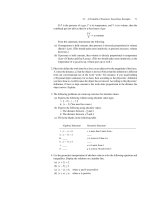
83: Head pulley bearing arrangement of a belt conveyor
Internal bearings for the tension/
84 take-up pulley of a belt conveyor
Non-driven pulleys in belt conveyors are frequently fit-
ted with internal bearings. The bearings are integrated
into the pulley so that the pulley body revolves about
the stationary shaft.
Operating data
Belt width 3,000 mm; belt speed 6 m/s; pulley diame-
ter 1,000 mm; pulley load 1,650 kN.
Bearing selection, dimensioning
These pulleys are supported either in two spherical
roller bearings (fig. a) or in two cylindrical roller bear-
ings (fig. b). The internal design of the cylindrical roll-
er bearings allows the rolling elements to accommodate
load-related shaft deflections without edge running.
In a spherical roller bearing arrangement, an FAG
23276BK.MB with an adapter sleeve FAG
H3276HGJ is used as locating bearing and an FAG
23276B.MB is used as floating bearing.
In a cylindrical roller bearing arrangement, the floating
bearing is an FAG 547400A and the locating bearing
an FAG 544975A. Both cylindrical roller bearings
have the main dimensions 360 x 680 x 240 mm and
are interchangeable with spherical roller bearings FAG
23276BK.MB with an adapter sleeve FAG
H3276HGJ.
The bearings must feature the required dynamic load
rating C/the required bore diameter. With an index of
dynamic stressing f
L
> 4, the bearings are sufficiently di-
mensioned with regard to fatigue life.
Often, the actual bearing life is considerably shorter
than the nominal rating life determined on the basis of
the f
L
value. The cause is wear in raceways and on roll-
ing elements as a result of adverse ambient conditions.
Improved cleanliness during mounting and in opera-
tion as well as the utilization of a suitable lubricant
have a positive effect on the bearing life. These influ-
ences are taken into account in the adjusted rating life
calculation and in the modified life calculation in accor-
dance with DIN ISO 281. It is used for example to
compare the effects of different lubricants. The fatigue
life calculated for pulley bearings with this method in
most cases is not equivalent to the attainable life as the
service life is mainly limited by wear.
Machining tolerances
In view of the circumferential load and the relatively
high amount of load the outer rings must be a very
tight fit in the pulley bore. Tolerances, see table below.
Lubrication, sealing
The bearings are lubricated with a lithium soap base
grease of penetration 2 with EP additives (FAG rolling
bearing grease Arcanol L186V).
External sealing of the bearings is provided by non-
rubbing labyrinth seals or multi-collar rubbing seals. In
both cases the labyrinths are filled with the same grease
as the bearings. To supply the bearings with fresh
grease and to increase the sealing effect, relubrication is
effected at short intervals (depending on the amount
of dirt) via the stationary shaft.
Machining tolerances
Bearing Seat Diameter tolerance Cylindricity tolerance
Spherical roller bearing Shaft h8 IT5/2
as locating bearing Pulley bore M7 IT5/2
Spherical roller bearing Shaft g6 IT5/2
as floating bearing Pulley bore M7 IT5/2
Cylindrical roller bearing Shaft g6 IT5/2
locating bearing, floating bearing Pulley bore N7 IT5/2
84: Internal bearings for the tension / take-up pulley of a belt conveyor
a
b
Belt conveyor idlers
Many industries use belt conveyors for transporting
bulk materials. The conveyors run on idlers and may
extend over many miles; thus the number of idlers
needed may be very large. Consequently, bearing
mounting design is dictated by cost-saving considera-
tions.
Idler arrangement
Small belt conveyor systems feature idlers rigidly
linked to a frame. Large belt conveyor systems feature
idler garlands linked to each other by flexible joints.
85 Rigid idlers
Operating data
Capacity I
m
= 2,500 t/h; Design: troughed belt with
three idlers per station; the two outer idlers are ar-
ranged at an angle of 30° to the horizontal; distance
between two idler stations l
R
= 1,200 mm; idler diame-
ter d = 108 mm, belt weight G
G
= 35 kg/m, dead-
weight per roller G
R
= 6 kg; belt speed v = 3 m/s; accel-
eration due to gravity g = 9.81 m/s
2
.
Bearing selection
Idler mountings are usually internal bearing arrange-
ments (hub mountings), i.e. the idler rotates about a
stationary shaft.
Since a belt conveying plant requires a large number of
roller bearings, deep groove ball bearings, which are
produced in large quantities at low cost, are preferably
used. This allows a simple and economical idler design.
85a c: Idler sealing variations
Bearing dimensioning
Idler speed n =
v · 60 · 1,000
= 530 min
–1
d · π
For ball bearings, the speed factor f
n
= 0.4.
Load per idler station:
F = g · l
R
·
(
I
m
+ G
G
)
=
3.6 · v
= 9,81 · 1,2 ·
(
2,500
+ 35
)
= 3,137 N
3.6 · 3
For a trough angle of 30° the horizontal centre idler
takes up approximately 65 % of this load. Thus the
load on the centre idler is
F
R
= 0.65 · F + g · G
R
= 0.65 · 3,137 + 9.81 · 6 =
= 2,100 N = 2.1 kN
Equivalent dynamic bearing load:
P = F
r
= F
R
/2 = 1.05 kN
The usual index of dynamic stressing for idler bearings
f
L
= 2.5 3.5. With f
L
= 3, the required dynamic load
rating C of a bearing
C = f
L
· P/f
n
= 3 · 1.05/0.4 = 7.88 kN
Deep groove ball bearings FAG 6204.2ZR.C3 having
a dynamic load rating C = 12.7 kN are mounted.
a b c
86 Idler garland
Generally, the service life of a bearing is not terminated
by fatigue but by wear in raceways and on rolling ele-
ments as a result of contamination. Increased cleanli-
ness during mounting and efficient sealings increase
the bearing life. The ajdusted rating life calculation is
used for comparing different seal designs.
New idler bearings feature utmost cleanliness (V =
0.3). However, in the course of operation the lubricant
gets heavily contaminated by particles (V = 3).
As the bearings in belt conveyor systems fail as a result
of wear, the values obtained by the adjusted rating life
calculation (L
hna
) usually are not equivalent to the actu-
ally attainable lives.
Machining tolerances
The two deep groove ball bearings are mounted onto
the idler shaft in a floating bearing arrangement. As the
inner rings are subjected to point load the shaft is ma-
chined to h6 or js6. The outer rings are subjected to
circumferential load and are pressed, therefore, into the
idler end with an M7 interference fit.
Lubrication, sealing and maintenance
The deep groove ball bearings FAG 6209.2ZR.C3 are
packed, at the manufacturing plant, with a lithium
soap base grease of penetration class 2 which is suffi-
cient for the entire bearing service life. Such a grease is
also used for the sealing.
With idler bearings, both the attainable life and the lu-
bricant service life may be considerably reduced by
grease contamination during operation so that the seal-
ing selected is decisive. Figs. 85a c show various types
of sealing for belt conveyor idlers.
Simple seals (figs. 85a and b) are used for clean envi-
ronments. Fig. 85c shows an idler seal for brown coal
open pit mining.
In addition to the rigidly troughed belt conveyors the
garland type belt conveyors are being increasingly
used. The idlers of each station are linked to each other
by flexible joints. These joints may consist of a wire
rope, a chain link (flat chain, round chain), hinge or
similar.
Idler garlands accommodate impacts elastically; in the
event of problems with a roller the individual garland
is lowered and can be replaced relatively easily if neces-
sary.
Fig. 86 shows idler garlands connected by chain links.
These idlers are part of a conveying installation for
rock phosphate. The bearings fitted are deep groove
ball bearings FAG 6303.2ZR.C3.
Machining tolerances
Idler ends to M7, shaft to h6 or js6.
Lubrication, sealing, maintenance
The deep groove ball bearings (design .2ZR) are sealed
by dust shields on both sides and filled with FAG roll-
ing bearing grease, a lithium soap base grease of pene-
tration class 2. The grease filling suffices for idler ser-
vice life. A grease chamber with a non-rubbing laby-
rinth seal is provided at the outboard end. The second,
adjacent chamber is closed by a shield pressed into the
hub bore. A baffle plate protects the bearing against
coarse particles.
86: Idlers connected by chain link
87 Bucket wheel shaft of a bucket wheel excavator
Bucket wheel excavators are mainly used for brown
coal open pit mining. The bucket wheel shaft carries
the bucket wheel, the bull gear and the transmission
housing. It is supported in the boom ends.
Operating data
Input power 3 x 735 kW; theoretical conveying capac-
ity 130,000 m
3
/ day; bucket wheel speed 3 min
–1
.
Bearing selection
The bearings of the bucket wheel shaft are subjected to
high shock-type loads. Moreover, shaft deflections and
misalignments must be expected. For this reason, only
self-aligning roller bearings are suitable for supporting
the shaft. At both shaft ends, spherical roller bearings
FAG 239/900K.MB with withdrawal sleeves FAG
AH39/900H are mounted as locating bearings. Ther-
mal length variations of the shaft are compensated for
by the elastic surrounding structure. The radial clear-
ance of the spherical roller bearings is eliminated dur-
ing mounting by pressing in the withdrawal sleeves.
Only a split bearing can be provided on the bucket
wheel side of the transmission box due to the solid
forged shaft flange to which the bull gear is attached. If
an unsplit bearing were to be provided on the opposite
side of the transmission box it could only be replaced
after dismounting the spherical roller bearing first.
For this purpose the entire bucket wheel shaft would
have to be removed from the boom. This is avoided by
using a split FAG cylindrical roller bearing of dimen-
sions 1,000 x 1,220 x 170/100 mm on this side as
well. The increased axial clearance of the two cylindri-
cal roller bearings yields a floating bearing arrangement.
Each bearing accommodates axial guiding loads in
only one direction. The inner ring halves are attached
to the shaft by means of separate locking rings. The
calculated nominal rating life of all bearings is over
75,000 hours.
Machining tolerances
All inner rings are subjected to circumferential load.
The spherical roller bearings FAG 239/900K.MB are
hydraulically fastened to the shaft (machined to h8) by
means of withdrawal sleeves FAG AH39/900H. The
split cylindrical roller bearings sit directly on the shaft
which is machined to m6 in this place. All outer ring
seats are toleranced to H7.
Lubrication, sealing
The spherical roller bearings are oil-bath lubricated.
The split cylindrical roller bearings are supplied by the
draining oil from gearwheel lubrication.
The sealing is a combination of labyrinth and rubbing
seal. The labyrinths at the spherical roller bearings can
be relubricated.
87: Bucket wheel mounting
88 Bottom sprocket of a bucket chain dredger
Bucket chain dredgers perform dredging work in
waterways. The buckets are carried by a continuous
chain from the bottom sprocket to the top sprocket
over a large number of support rolls and back.
shaft call for self-aligning bearings. The bearings used
are spherical roller bearings FAG 22240B.MB. Both
bottom sprocket shaft bearings are designed as locating
bearings. However, the bearings are not nipped axially,
the housing being mounted with clearance in its ladder
yoke seat. For easier bearing dismounting the shaft
journal is provided with oilways and grooves for hy-
draulic dismounting.
Machining tolerances
Circumferential load on the inner ring.
Shaft journal to m6; housing to J7.
Lubrication, sealing
The grease in the bearing (FAG rolling bearing grease
Arcanol L186V) is renewed at intervals of 1 1/2 to 2
years coinciding with the general overhaul period of
the dredger.
The bottom sprocket is constantly immersed in water.
This requires waterproof sealing. Each bearing location
is, therefore, fitted with two rubbing seals (shaft seals
with bronze garter spring) and, in addition, with two
packing rings (stuffing box). The shaft seals run on a
bush of seawater-resistant material. The stuffing box
can be retightened by means of a cover. Grease is regu-
larly pumped into the labyrinth between the shaft seals
and packing rings.
Operating data
Ladder length 32 m; number of buckets 44; maximum
dredging depth approximately 14 m; radial load on
bottom sprocket approximately 250 kN.
Bearing selection
Rugged operation and unvoidable misalignment
between the housings at both ends of the sprocket
88: Bottom sprocket of a bucket chain dredger
89 Drive unit of a finished goods elevator
Finished-goods elevators are used, for example, for
charging salt granulating plants. The material is
conveyed in buckets attached to a chain. The chain is
driven by the tumbler situated at the upper end.
Operating data
Input power 22 kW; speed 13.2 min
–1
; radial bearing
load 90 kN.
Bearing selection
As shaft deflections and misalignments have to be ex-
pected the drive shaft is supported on self-aligning
bearings. Selecting split spherical roller bearings FAG
222SM125T ensures that the heavy drive unit with
the torque arm does not have to be dismounted in the
event of repair.
As a result, the downtimes of the plant and the cost of
production loss are considerably lower than they
would be with one-piece bearings. To limit the variety
of bearings used, a split spherical roller bearing was
provided at the free shaft end as well.
Split spherical roller bearings have a cylindrical bore.
Inner ring, outer ring and cage with roller set are split
into halves.
The split inner ring halves are braced together by
means of four dowel screws and attached to the shaft.
Both outer ring halves are fitted together without a gap
by means of two dowel screws.
The drive-end bearing is mounted with two locating
rings and acts as the locating bearing; the bearing at the
opposite end is the floating bearing. Split spherical roll-
er bearings FAG 222SM125T are designed in such a
way that they can be mounted into split series hous-
ings FAG SNV250 instead of one-piece spherical roller
bearings with an adapter sleeve. Outside diameter, out-
er ring width and shaft seat diameter are identical.
The theoretical fatigue life L
h
of the bearings is over
100,000 hours.
Machining tolerances
Shaft to h6 h9;
housing to H7
Lubrication, sealing
The bearings are lubricated with grease. The housings
are connected to a central lubricating system so that
continuous relubrication is ensured.
The shaft openings on both sides of the housing are
each sealed by a two-lip seal.
89: Drive unit of a finished goods elevator
The Design of Rolling Bearing Mountings
PDF 6/8:
Construction machinery
Raw material processing
Steel mill and rolling mill equipment
Agricultural machinery · Food industry
Rolling Bearings
FAG OEM und Handel AG Publ. No. WL 00 200/5 EA
The Design of
Rolling Bearing Mountings
Design Examples covering
Machines, Vehicles and Equipment
Publ. No. WL 00 200/5 EA
FAG OEM und Handel AG
A company of the FAG Kugelfischer Group
Postfach 1260 · D-97419 Schweinfurt
Telephone (0 97 21) 91-0 · Telefax (0 97 21) 91 34 35
Telex 67345-0 fag d
Preface
This publication presents design examples covering
various machines, vehicles and equipment having one
thing in common: rolling bearings.
For this reason the brief texts concentrate on the roll-
ing bearing aspects of the applications. The operation
of the machine allows conclusions to be drawn about
the operating conditions which dictate the bearing
type and design, the size and arrangement, fits, lubri-
cation and sealing.
Important rolling bearing engineering terms are print-
ed in italics. At the end of this publication they are
summarized and explained in a glossary of terms, some
supplemented by illustrations.
Contents
Example Title PDF
CONSTRUCTION MACHINERY
90 Driving axle of a construction machine . 6/8
91 Vibrating road roller . . . . . . . . . . . . . . . . 6/8
RAW MATERIAL PROCESSING
Crushers and mills
92 Double toggle jaw crusher . . . . . . . . . . . . 6/8
93 Hammer mill . . . . . . . . . . . . . . . . . . . . . . 6/8
94 Double-shaft hammer crusher . . . . . . . . 6/8
95 Ball tube mill . . . . . . . . . . . . . . . . . . . . . . 6/8
96 Support roller of a rotary kiln . . . . . . . . . 6/8
Vibrating machines . . . . . . . . . . . . . . . . . 6/8
97 Two-bearing screen with circle throw . . . 6/8
98 Two-bearing screen with straight-line
motion . . . . . . . . . . . . . . . . . . . . . . . . . . . 6/8
99 Four-bearing screen . . . . . . . . . . . . . . . . . 6/8
100 Vibrator motor . . . . . . . . . . . . . . . . . . . . 6/8
STEEL MILL AND ROLLING MILL
EQUIPMENT
101-103 Large-capacity converters . . . . . . . . . . . . 6/8
104 Roll bearings of a non-reversing four-
high cold rolling stand for aluminium . . 6/8
105 Work rolls for the finishing section of a
four-high hot wide strip mill . . . . . . . . . . 6/8
106 Roll mountings of a two-high ingot
slab stand or ingot billet stand . . . . . . . . 6/8
107 Combined reduction and cogging
wheel gear of a billet mill . . . . . . . . . . . . . 6/8
108 Work rolls of a section mill . . . . . . . . . . . 6/8
109 Two-high rolls of a dressing stand for
copper and brass bands . . . . . . . . . . . . . . 6/8
110 Straightening rolls of a rail straightener . 6/8
AGRICULTURAL MACHINERY ·
FOOD INDUSTRY
111 Disk plough . . . . . . . . . . . . . . . . . . . . . . . 6/8
112 Plane sifter . . . . . . . . . . . . . . . . . . . . . . . . 6/8
90 Driving axle of a construction machine
Modern construction machines feature planetary gears
in the wheel hub. This yields a considerable step-down
ratio in a limited space, in the example shown i
g
=
6.35. As the considerable drive torque is generated im-
mediately at the wheel, a light drive shaft is sufficient.
Planet wheel bearing arrangement
The planet wheel bearings must provide a high load
carrying capacity in a limited space. This is achieved
by means of assemblies where the outer ring raceway is
integrated in the planet wheel. The self-aligning spheri-
cal roller bearing selected in the example smoothly
compensates for small misalignments resulting from
the deflection of the cantilever bearing journal under
load. This yields a uniform contact pattern for the
gearing, which is indicative of an optimal gear mesh.
In the example shown the internal design of spherical
roller bearing FAG 22309E.TVPB is used.
Wheel mounting
As a rule, the wheel mounting on rigid axles of con-
struction machines consists of two tapered roller bear-
ings which are axially adjusted against each other in O
arrangement (larger spread ) and with preload. In this
way, deformations and tilting of the planetary gear are
minimized and impermissible plastic deformations
(brinelling marks) resulting from adverse operating
conditions avoided.
The wheel bearings are tapered roller bearings FAG
32021X (in accordance with DIN ISO 355:
T4DC105) and FAG 32024X (T4DC120).
Machining tolerances
The rotating outer rings of the wheel mounting are
subjected to circumferential load, the stationary inner
rings to point load, therefore: journal to k6; hub to N7.
Lubrication, sealing
Rolling bearings and gearing are washed around in the
revolving wheel hub by the transmission oil.
Radial shaft seals protect the bearings from dirt and
splash water.
90: Driving axle of a construction machine
91 Vibrating road roller
The vibrations of such road rollers are produced by an
eccentric shaft.
Operating data
Speed of eccentric shaft n = 1,800 min
–1
; radial load
F
r
= 238 kN; number of bearings z = 4; required nomi-
nal rating life L
h
≥ 2,000 hours.
Bearing selection, dimensioning
The centrifugal force from the imbalance weights on
both sides of the roll are accommodated by two bear-
ings each. The equivalent dynamic load per bearing is:
P = 1/z · F
r
= 1/4 · F
r
= 59.5 kN
For the above conditions, an index of dynamic stressing
f
L
= 1.52 and a speed factor of f
n
= 0.302 are obtained.
The adverse dynamic stressing is taken into account by
introducing a supplementary factor f
z
= 1.2. Thus, the
required dynamic load rating of one bearing
C = f
L
/f
n
· P · f
z
= 1.52/0.302 · 59.5 · 1.2 = 359.4 kN
On each side of the imbalance weights a cylindrical
roller bearing FAG NJ320E.M1A.C4 (dynamic load
rating C = 380 kN) is mounted. Due to the vibratory
loads the bearings are fitted with an outer ring riding
machined brass cage (M1A). The misalignment
between the two bearing locations from housing
machining inaccuracies is less than that permissible for
cylindrical roller bearings.
Machining tolerances
In view of the vibrations it is advisable to provide tight
fits for both the bearing inner and outer rings. Axial
guidance of the eccentric shaft is provided by the lips
of the cylindrical roller bearings.
Eccentric shaft to k5, housing bore to M6.
Lubrication, sealing
The bearings are lubricated by the oil splashed off from
the imbalance weights. Additional guide plates im-
prove lubricant supply to the bearings. Mineral oils
with EP additives and anti-corrosion additives have
proved to be suitable.
Internal sealing is provided by shaft seals, external seal-
ing by O-ring seals.
91: Vibrating road roller