Lubrication and Reliability Handbook 2010 Part 7 doc
Bạn đang xem bản rút gọn của tài liệu. Xem và tải ngay bản đầy đủ của tài liệu tại đây (677.3 KB, 20 trang )
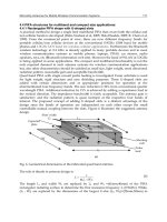
A29 High pressure and vacuum
A29.2
Effect of dissolved gases on the viscosity of
mineral oils
An estimate of the viscosity of oils saturated with gas can
be obtained as follows:
(i) Determine Ostwald coefficient for gas in mineral oil
from Figure 29.4.
(ii) Calculate gas: oil ratio from:
Gas: oil ratio
= Ostwald coefficient p ·
293
+ 273
(1)
where p is the mean gas pressure (bar), and the
mean temperature (°C).
(iii) Obtain viscosity of oil saturated with gas(es) from:
s
= A
b
o
(2)
where
o
is the viscosity of oil at normal atmospheric
pressure (CSt); and A, b are constants obtained
from Figure 29.5.
Figure 29.3 Compressibility of typical mineral oils
Figure 29.4 Ostwald coefficients for gases in
mineral lubricating oils
Figure 29.5 Constants for eqn (2)
A29High pressure and vacuum
A29.3
VACUUM
Lubricant loss by evaporation
Table 29.1 Lubricants and coatings which have been used in high vacuum
A29 High pressure and vacuum
A29.4
Loss of surface films in high vacuum
Surface contaminant films of soaps, oils and water, etc.,
and surface layers of oxides, etc., enable components to
rub together without seizure under normal atmospheric
conditions. Increasing vacuum causes the films to be lost,
and reduces the rate at which oxide layers reform after
rubbing. The chance of seizure is therefore increased.
Seizure can be minimised by using pairs of metals
which are not mutually soluble, and Table 29.2 shows
some compatible common metals under high vacuum
conditions, but detailed design advice should usually be
obtained.
Table 29.2 Some compatible metal pairs for
vacuum use
A30High and low temperatures
A30.1
HIGH TEMPERATURE
Temperature limitations of liquid lubricants
The chief properties of liquid lubricants which impose
temperature limits are, in usual order of importance, (1)
oxidation stability; (2) viscosity; (3) thermal stability; (4)
volatility; (5) flammability.
Oxidation is the most common cause of lubricant
failure. Figure 30.1 gives typical upper temperature limits
when oxygen supply is unrestricted.
Compared with mineral oils most synthetic lubricants,
though more expensive, have higher oxidation limits,
lower volatility and less dependence of viscosity on
temperature (i.e. higher viscosity index).
For greases (oil plus thickener) the usable tem-
perature range of the thickener should also be con-
sidered (Figure 30.2).
Temperature limitations of solid lubricants
All solid lubricants are intended to protect surfaces from
wear or to control friction when oil lubrication is either
not feasible or undesirable (e.g. because of excessive
contact pressure, temperature or cleanliness
requirements).
There are two main groups of solid lubricant, as given
in Table 30.1.
Figure 30.1
Figure 30.2
Table 30.1
A30 High and low temperatures
A30.2
Dry wear
When oil, grease or solid lubrication is not possible, some metallic wear may be inevitable but oxide films can be
beneficial. These may be formed either by high ambient temperature or by high ‘hot spot’ temperature at asperities, the
latter being caused by high speed or load.
Examples of ambient temperature effects are given in Figures 30.3 and 30.4, and examples of asperity temperature
effects are given in Figures 30.5 and 30.6.
Bearing materials for high temperature use
When wear resistance, rather than low friction, is important, the required properties (see Table 30.2) of bearing
materials depend upon the type of bearing.
Figure 30.3 Wear of brass and aluminium alloy
pins on tool steel cylinder, demonstrating oxide
protection (negative slope region). Oxide on
aluminium alloy breaks down at about 400°C, giving
severe wear
Figure 30.4 Wear of (1) nitrided EN41A; (2) high
carbon tool steel; (3) tungsten tool steel. Oxides:
␣Fe
2
O
3
below maxima; ␣Fe
3
O
4
-type above maxima
Figure 30.5 Wear of brass pin on tool steel-ring. At
low speed wear is mild because time is available for
oxidation. At high speed wear is again mild because of
hot-spot temperatures inducing oxidation
Figure 30.6 Transition behaviour of 3% Cr steel.
Mild wear region characterised by oxide debris: severe
wear region characterised by metallic debris
Table 30.2
A30High and low temperatures
A30.3
Hot hardness, particularly in rolling contact bearings,
is of high importance and Figure 30.7 shows maximum
hardness for various classes of material.
Some practical bearing materials for use in oxidising
atmospheres are shown in Table 30.3.
LOW TEMPERATURE
General
‘Low temperature’ may conveniently be subdivided into
the three classes shown in Table 30.4. In Class 1, oils are
usable depending upon the minimum temperature at
which they will flow, or the ‘pour point’. Some typical
values are given in Table 30.5. Classes 2 and 3 of Table 30.4
embrace most industrially important gases (or cryogenic
fluids) with the properties shown in Table 30.6.
Because of their very low viscosity (compare to 7
10
–2
Ns/m
2
for SAE 30 oil at 35°C) these fluids are
impractical as ‘lubricants’ for hydrodynamic journal
bearings. (Very high speed bearings are theoretically
possible but the required dimensional stability and
conductivity are severe restrictions.)
Figure 30.7
Table 30.3
Table 30.4
Table 30.5
Table 30.6
A30 High and low temperatures
A30.4
Unlubricated metals
In non-oxidising fluids, despite low temperature, metals
show adhesive wear (galling, etc.) but in oxygen the wear
is often less severe because oxide films may be formed.
Where there is condensation on shafts, seals or ball
bearings (dry lubricated) a corrosion-resistant hard steel
(e.g. 440°C) is preferable.
Plain bearing materials
As bushes and thrust bearings, filled PTFE/metal and
filled graphite/metal combinations are often used – see
Table 30.8.
Safety
Aspects of safety are summarised in Table 30.7.
Ball bearings and seals for cryogenic temperatures
Table 30.7
Table 30.8 Some successful plain bearing
materials for cryogenic fluids
Table 30.9 Recommended tribological practice at cryogenic temperatures
A31Chemical effects
A31.1
This section is restricted to chemical effects on metals.
Chemical effects can arise whenever metals are in contact with chemicals, either alone or as a contaminant in a
lubricant.
Wear in the presence of a corrosive liquid can lead to accelerated damage due to corrosive wear. This problem is
complex, and specialist advice should be taken.
Corrosion or corrosive wear are often caused by condensation water in an otherwise clean system.
SELECTION OF CORROSION RESISTANT MATERIALS FOR CONTACT WITH VARIOUS LIQUIDS
Table 31.1 Some specific contamination situations
Table 31.2 Typical corrosion resistant materials
A31 Chemical effects
A31.2
A31Chemical effects
A31.3
This Page Intentionally Left Blank
B1Maintenance methods
B1.1
The purpose of maintenance is to preserve plant and machinery in a condition in which it can operate, and can do so
safely and economically.
It is the components of plant and machinery which fail individually, and can lead to the loss of function of the whole
unit or system. Maintenance activity needs therefore to be concentrated on those components that are critical.
Table 1.1 Situations requiring maintenance action
Table 1.2 Factors in the selection of critical components
B1 Maintenance methods
B1.2
Table 1.3 Maintenance methods which can be used
B1Maintenance methods
B1.3
Figure 1.1 The results of maintaining the same industrial plant in different ways. The height of the bars
indicates the amount of maintenance effort required
B1 Maintenance methods
B1.4
The components of machines do not fail at regular
intervals but show a range of times to failure before and
after a mean time.
If it is essential that no failures occur in service, the
components must be changed within the time that the
earliest failure may be expected.
Figure 1.2 The distribution of the time to failure for a typical component
Table 1.4 Feedback from maintenance to equipment design
B1Maintenance methods
B1.5
Table 1.5 Maintenance management
B2 Condition monitoring
B2.1
Condition monitoring is a technique used to monitor the condition of equipment in order to give an advanced warning
of failure. It is an essential component of condition-based maintenance in which equipment is maintained on the basis
of its condition.
MONITORING METHODS
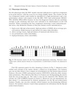
The basic principle of condition monitoring is to select a
physical measurement which indicates that deterioration
is occurring, and then to take readings at regular
intervals. Any upward trend can then be detected and
taken as an indication that a problem exists. This is
illustrated in Figure 2.1 which shows a typical trend curve
and the way in which this provides an alert that an
incipient failure is approaching. It also gives a lead time
in which to plan and implement a repair.
Since failures occur to individual components, the
monitoring measurements need to focus on the partic-
ular failure modes of the critical components.
The monitoring measurements give an indication of the existence of a problem as shown in Figure 2.1. More detailed
analysis can indicate the nature of the problem so that rectification action can be planned. Other sections of this
handbook give more details about these methods of monitoring.
In wear debris monitoring, the amount of the debris and its rate of generation indicate when there is a problem. The
material and shape of the debris particles can indicate the source and the failure mechanism.
The overall level of a vibration measurement can indicate the existence of a problem. The form and frequency of the
vibration signal can indicate where the problem is occurring and what it is likely to be.
Figure 2.1 The principle of condition monitoring
measurements which give an indication of the
deterioration of the equipment
Table 2.1 Monitoring methods and the components for which they are suitable
B2Condition monitoring
B2.2
Introducing condition monitoring
If an organisation has been operating with breakdown maintenance or regular planned maintenance, a change over to
condition-based maintenance can result in major improvements in plant availability and in reduced costs. There are,
however, up front costs for organisation and training and for the purchase of appropriate instrumentation. There are
operational circumstances which can favour or retard the potential for the introduction of condition-based
maintenance.
Table 2.2 Factors which can assist the introduction of condition-based maintenance
Table 2.3 Factors which can retard the introduction of condition-based maintenance
B2 Condition monitoring
B2.3
Table 2.4 A procedure for setting up a plant condition monitoring activity
Table 2.5 Problems which can arise
B2Condition monitoring
B2.4
Table 2.6 The benefits that can arise from the use of condition monitoring