Manufacturing Design, Production, Automation, and Integration Part 6 pptx
Bạn đang xem bản rút gọn của tài liệu. Xem và tải ngay bản đầy đủ của tài liệu tại đây (732.08 KB, 36 trang )
Part II
Discrete-Parts Manufacturing
Manufacturing, in its broadest form, refers to ‘‘the design, fabrication
(production), and, when needed, assembly of a product.’’ In its narrower
form, however, the term has been frequently used to refer to the actual
physical creation of the product. In this latter context, the manufacturing of
a product based on its design specifications is carried out in a discrete-parts
mode (e.g., car engines) or a continuous-production mode (e.g., powder-
form ceramic). In this part of the book, our focus is on the manufacturing
(i.e., fabrication and assembly) of discrete parts. Continuous-production
processes used in some metal, chemical, petroleum, and pharmaceutical in-
dustries will not be addressed herein.
In Chap. 6, three distinct fusion-based production processes are de-
scribed for the net-shape fabrication of three primary engineering materials:
casting for metals, powder processing for ceramics and high-melting-point
metals and their alloys (e.g., cermets), and molding for plastics. In Chap. 7,
several forming processes, such as forging and sheet forming, are discussed as
net-shape fabrication techniques alternative to casting and powder proces-
sing of metals. One must note, however, that it is the manufacturing en-
gineer’s task to evaluate and choose the optimal fabrication process among
all alternatives based on the specifications of the product at hand.
Copyright © 2003 by Marcel Dekker, Inc. All Rights Reserved.
In Chap. 8, several traditional material-removal techniques, such as
turning, milling, and grinding, collectively termed as ‘‘ machining, ’’ are de-
scribed. These techniques can yield parts that are dimensionally more ac-
curate than those achievable by net-shape-fabrication methods. In practice,
for mass-production cases, it is common to fabricate rough-shaped ‘‘blank’’
parts using casting or forming prior to their machining.
In Chap. 9, the emphasis is on nontraditional fabrication methods,
such as electrical-discharge machining, lithography, and laser cutting, for
part geometries and materials that are difficult to fabricate using tradition-
al machining and/or forming techniques. Rapid layered fabrication of pro-
totypes is also addressed in this chapter. A common constraint to all
nontraditional (material-removal or material-additive) techniques is their re-
striction to one-of-a-kind or small-batch production.
In Chap. 10, several joining methods, such as mechanical fastening,
adhesive bonding, welding, brazing, and soldering, are described as part of
an overall discussion on product assembly. Automatic population of
electronic boards and automatic assembly of small mechanical parts are
also described in this chapter as exemplary applications of assembly.
In Chap. 11, workholding (fixturing) principles are discussed for the
accurate and secure holding of workpieces in manufacturing. Numerous
fixed-configuration (i.e., dedicated) jig and fixture examples are discussed
for machining and assembly. Furthermore, several modular and reconfigu-
rable systems are highlighted for flexible manufacturing.
In Chap. 12, common material-handling technologies, such as pow-
ered trucks, automated guided vehicles, and conveyors, targeted for the
transportation of unit goods between manufacturing workcells, are de-
scribed. The role of industrial robots in the movement of workpieces and
tools within a workcell is also discus sed in this chapter. The assembly of
automobiles is addressed as an exemplary application area.
Part II164
Copyright © 2003 by Marcel Dekker, Inc. All Rights Reserved.
6
Metal Casting, Powder Processing,
and Plastics Molding
This chapter presents net shape fabrication processes for three primary
classes of engineering materials: casting for metals, powder processing
for ceramics and (high-melting-temperature) metal alloys, and molding
for plastics.
6.1 METAL CASTING
Casting is a term normally reserved for the net shape formation of a metal
object by pouring (or forcing) molten (metal) material into a mold (or a
die) and allowing it to solidify. The molten metal takes the shape of the
cavity as it solidifies. Cast objects may be worked on further through other
metal-forming or machining processes in order to obtain more intricate
shapes, better mechanical properties, as well as higher tolerances. Over its
history, casting has also been referred to as a founding process carried out
at foundries.
6.1.1 Brief History of Casting
Casting of metals can be traced back in history several thousand years.
Except in several isolated cases, however, these activities were restricted to
the processing of soft metals with low melting temperatures (e.g., silver and
Copyright © 2003 by Marcel Dekker, Inc. All Rights Reserved.
gold used for coins or jewellery). An isolated case of using iron in casting has
been traced to China, which is claimed to be possible owing to the high
phosphorus content of the ore, which allowed melting at lower temperatures.
Casting of iron on the European continent has been traced back to the
period A.D. 1200–1300, the time of the first mechanized production of metal
objects, in contrast to earlier manual forming of metals. During the period
A.D. 1400–1600, the primary customers of these castings were the European
armies, in their quest of improving on the previously forged cannons and
cannon balls. However, owing to their enormous weight, the large cannon
had to be poured at their expected scene of operation.
The first two commercial foundries in North America are claimed to
be the Braintree and Hammersmith ironworks of New England in early
1600s. Most of their castings were manufactured by solidifying molten metal
in trenches on the foundry floor (for future forging) or poured into loam- or
sand-based molds. Wood-based patterns were commonly used in the shap-
ing of the cavities.
Despite the existence of numerous foundries in America, one of the
world’s most famous castings, the Liberty Bell (originally called the
Province Bell) was manufactured in London, England, in 1775, owing to
a local scarcity of bronze in the U.S.A. The bell, which cracked in 1835, has
been examined and classified as a ‘‘ poor casting’’ (being gassy and of poor
surface finish). Cannon and bells were followed by the use of castings in the
making of stoves and steam-engine parts. Next came the extensive use of
castings by the American railroad companies and the Canadian Pacific
Railroad. Their locomotives widely utilized cast-iron-based wheel centers,
cylinders and brakes, among many other parts. Although the railroad
continues to use castings, since the turn of the 20th century, the primary
user of cast parts has been the automotive industry.
6.1.2 Casting Materials
The most common casting material is iron. The widely used generic term
cast iron refers to the family of alloys comprising different proportions of
alloying material for iron—carbon and silicon, primarily, as well as man-
ganese, sulphur, and phosphorus:
Gray cast iron: The chemical composition of gray cast iron contains
2.5–4% carbon, 1–3% silicon, and 0.4–1% manganese. Due to its casting
characteristics and cost, it is the most commonly used material (by weight).
Its fluidity makes it a desirable material for the casting of thin and intricate
features. Gray cast iron also has a lower shrinkage rate, and it is easier to
machine. A typical application is its use in the manufacture of engine blocks.
Gray cast iron can be further alloyed with chromium, molybdenum, nickel,
Chapter 6166
Copyright © 2003 by Marcel Dekker, Inc. All Rights Reserved.
copper, or even titanium for increased mechanical properties—strength,
resistance to wear, corrosion, abrasion, etc.
Ductile cast iron: The chemical composition of ductile cast iron (also
known as nodular or spheriodal graphite cast iron) contains 3–4% carbon,
1.8–2.8% silicon, and 0.15–0.9% manganese. First introduced in the late
1940s, this material can also be cast into thin sections (though not as well as
gray cast iron). It is superior in machinability to gray cast iron at equivalent
hardness. Its corrosion and wear resistance is superior to steel and equiv-
alent to gray cast iron. Typical uses of ductile cast iron include gears,
crankshafts, and cams.
Malleable iron: The chemical composition of malleable iron contains
2–3.3% carbon, 0.6–1.2% silicon, and 0.25–0.65% manganese. It can
normally be obtained by heat-treating white iron castings. The high strength
of malleable iron combined with its ductility makes it suitable for applica-
tions such as camshaft brackets, differential carriers, and numerous hous-
ings. One must note that malleable iron must be hardened in order to
increase its relatively low wear resistance.
Other typical casting materials include
Aluminum and magnesium alloys: Aluminum is a difficult material to
cast and needs to be alloyed with other metals, such as copper, magnesium,
and zinc, as well as with silicon (up to 12–14%). In general, such alloys
provide good fluidity, low shrinkage, and good resistance to cracking. The
mechanical properties obtainable for aluminum alloys depend on the
content of the alloying elements as well as on heat-treatment processes.
Magnesium is also a difficult material to cast in its pure form and is
normally alloyed with aluminum, zinc, and zirconium. Such alloys can have
excellent corrosion resistance and moderate strengths.
Copper-based alloys: Copper may be alloyed with many different
elements, including tin, lead, zinc, and nickel to yield, among others, a
common engineering alloy known as bronze (80–90% copper, 5–20% tin,
and less then 1–2% of lead, zinc, phosphorous, nickel, and iron).
Steel castings: These castings have isotropic uniformity of properties,
regardless of direction of loading, when compared to cast iron. However,
the strength and ductility of steel becomes a problem for the casting process,
for example, causing high shrinkage rates. Low-carbon steel castings
(< 0.2% carbon) can be found in numerous automotive applications, where-
as high-carbon cast steels (0.5% carbon) are used for tool and die making.
6.1.3 Sand Casting
Numerous advantages make casting a preferred manufacturing process over
other metal fabrication processes. Intricate and complex geometry parts can
Metal Casting, Powder Processing, and Plastic Molding 167
Copyright © 2003 by Marcel Dekker, Inc. All Rights Reserved.
be cast as single pieces, avoiding or minimizing subsequent forming and/or
machining operations and occasionally even assembly operations; parts can
be cast for mass production as well as for batch sizes of only several units
and extremely large and heavy parts (thousands of kilograms) may be cast
(as the only economically viable process of fabrication).
Among the numerous available techniques, sand casting is the most
common casting process for ferrous metals (especially for large size objects
such as automotive engine blocks). In sand casting, patterns are used for
the preparation of the cavities, and cores are placed in the mold thereafter
for obtaining necessary internal details. Due to the mostly mass produc-
tion nature of the utilization of sand casting, the mold-making process
and subsequent filling of the cavities is highly mechanized (usually in flow-
line environments).
Pattern Making
Pattern making is the first step in the construction of a mold, with the
exception of die-casting molds. Historically, mold cavities have been gen-
erated by building the mold, in an iterative manner, around a given pattern
made of wear-resistance metal (for repeated use), plastics (for limited use), or
wax (for one-time use). These patterns have been either manually prepared
(i.e., cut or carved) by industrial designers or machined by numerous material
removal techniques (Chap. 8) based on the object’s CAD data. (The latest
technology used in pattern making is layered manufacturing—one such
commercially available rapid prototyping technology is stereolithography,
commonly used for the fabrication of thermoset plastic parts—Chap. 9).
During pattern making, one can also include the gating system, through
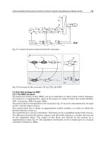
which the molten metal flows into the cavities, as part of the pattern (Fig. 1).
Furthermore, patterns can be manufactured in two halves (called the ‘‘ cope’’
and the ‘‘drag’’ patterns, or halves, of the mold), as opposed to a single-piece
pattern, for the individual production of the two halves of the mold.
Although a pattern is used to produce the mold cavity, neither the
pattern nor the cavity are dimensionally identical to the casting we intend to
manufacture. Patterns must allow for shrinkage during solidification, for
possible subsequent machining (namely, removal of some material to achieve
better surface accuracy and finish), for distortion in large plates or thin-
walled objects, and for ease of removal from the mold prior to casting.
Pattern making is followed by core making. Cores are patterns that are
placed into the mold cavities and remain there during the casting process in
order to yield the interior details of objects cast (Fig. 1). Naturally, they
should be easily removable from the casting after the cooling period. In sand
casting, cores are manufactured of sand aggregates.
One can realise that, for die casting applications, the pattern exists
only in the virtual domain—i.e., as a CAD solid model. In such cases, the
Chapter 6168
Copyright © 2003 by Marcel Dekker, Inc. All Rights Reserved.
mold is designed in the computer and its manufacturing operations are also
planned in the same CAD domain.
Mold Making
As mentioned above, the sand casting mold is normally made of two
halves—the cope and the drag. The sand used in making the mold is a
carefully proportioned mixture of sand grains, clay, organic stretches, and a
collection of synthetic binders. The basic steps of making a sand mold with
two half patterns are as follows (Fig. 2):
1. The (half) pattern is placed inside the walls of the cope half of
the mold.
2. The cope is filled with sand, which is subsequently rammed for
maximum tightness around the pattern as well as around the
gating system.
3. The pattern is removed.
FIGURE 1 Sand mold.
Metal Casting, Powder Processing, and Plastic Molding 169
Copyright © 2003 by Marcel Dekker, Inc. All Rights Reserved.
FIGURE 2 Mold-making and sand-casting process. (a) Cope pattern: ready to be
filled with sand. (b) Cope filled with sand; pattern removed. (c) Drag pattern; ready
to be filled with sand. (d) Drag filled with sand; pattern removed from drag. (e) Core
placed inside drag. (f) Cope and drag assembled; molten metal poured into mold.
(g) Metal cools and solidifies; casting removed from mold. Machining employed to
remove the gating system; final product.
Chapter 6170
Copyright © 2003 by Marcel Dekker, Inc. All Rights Reserved.
4. The second (half) pattern is placed inside the walls of the drag half
of the mold.
5. The drag is filled with sand, which is subseq uently rammed for
maximum tightness around the pattern.
6. The pattern is removed and cores are placed if necessary.
7. The two mold halves are clamped together for subsequent filling
of the cavities with molten metal.
8. The mold is opened after the cooling of the part and the
surrounding sand (incl uding the cores) are shaken out (through
forced vibration or shot blasting).
Most sand cast parts would need subsequent machining operations for
improved dimensional tolerances and better surface quality, which would
normally be in the range of 0.015 to 0.125 in (app. 0.4 to 4 mm) for tolerance
and 250 to 2000 Ain (app. 6 to 50 Am) for surface roughness (R
a
) (Chap. 16).
However, one must note that sand casting can yield a high rate of pro-
duction—hundreds of parts per hour.
6.1.4 Investment Casting
The investment casting process is also known as the lost wax process
because of the expendable pattern (usually made of wax) used in forming
the cavities. Although more costly than other casting processes, investment
casting can yield parts with intricate geometries and excellent surface quality
(15 to 150 Ain, or approximately 1 to 6 Am). The term investment refers to
the refractory mold that surrounds the wax pattern.
The basic steps of investment casting (mold making and casting) are as
follows (Fig. 3):
1. An accurate metal die is manufactured and used for the large-scale
production of wax patterns and gating systems.
2. The patterns are assembled into a multipart tree form and dipped
into a slurry of a refractory coating material (silica, water and other
binding agents). The tree is continuously lifted out and rotated to
produce uniform coating and drainage of excessive slurry.
3. The tree is sprinkled with silica sand and allowed to dry.
4. The tree is invested in a mold with a slurry and allowed to harden
(several hours to a day).
5. The mold is placed in an oven and the wax is melted off the
investment casting mold (up to a day).
6. Molten metal is poured into the cavities while the mold is still at a
high temperature.
7. The shells are broken and the castings cleaned.
Metal Casting, Powder Processing, and Plastic Molding 171
Copyright © 2003 by Marcel Dekker, Inc. All Rights Reserved.
Robots have been commonly used in the automation of the mold
making process for investment casting: manufacture of wax patterns,
assembly of trees, shell buildup, dewaxing, firing, casting, and cleaning.
6.1.5 Die Casting
Molds for multiuse must be made of comparably durable material (for
example, tool-grade steel) and utilized for long runs in order to be
economically viable. During the casting process, such molds would be
sprayed (with silica-type fluid) prior to pouring of the molten metal,
primarily to reduce wear. Molds are also be equipped with cooling systems
in order to reduce cycle times, as well as to control the mechanical properties
of the die cast part.
FIGURE 3 Investment casting. (a) Wax pattern. (b) Patterns attached to wax sprue.
(c) Patterns and sprue coated in slurry. (d) Patterns and sprue coated in stucco. (e)
Pattern melt-out. (f) Molten metal poured into mold; solidification. (g) Mold broken
away from casting; finishing part removed from sprue. (h) Finished part.
Chapter 6172
Copyright © 2003 by Marcel Dekker, Inc. All Rights Reserved.
In the above context, die casting is a permanent mold process, where the
molten metal is forced into the mold under high pressure, as opposed to
pouring it in (under gravitational force). Die casting offers low cost, excellent
dimensional tolerances and surface finish, and mass production capability
(with low cycle times).
Die casting fabrication processes can be traced back to the mid-1880s,
when it was used for the automatic production of metal letters. The develop-
ment of the automotive industry in the early 1900s, however, is accepted as
the turning point for die casting that first started with the production of
bearings. Today, many automotive parts (door handles, radiator grills,
cylinder heads, etc.) are manufactured through die casting (at rates of several
thousands per hour). Most such parts are made of zinc alloys, aluminum
alloys, or magnesium alloys.
As in other cases, a die casting mold comprises two halves. In this case
one of the halves is fixed and the other is moving (the ‘‘ejector’’ half). After
solidification, the casting remains in the moving half when the mold is
opened. It is then ejected by (mechanically or hydraulically activated) pins. In
order to prevent excessive friction with the fixed half and ease of ejection
from the moving half, the part should have appropriate draft angles. Internal
or external fins can be achieved by utilizing loose or moving die cores in the
fixed half of the die. (Average wall thicknesses of die cast parts range from 1.0
to 2.5 mm for different alloys.)
There exist two primary die casting processes, whose names are
derivatives of the machine configuration, more specifically, the locations of
the molten metal storage units (Fig. 4): in the hot chamber machine, the
molten metal storage unit is submerged in a large vat of molten material and
supplies the die casting machine with an appropriate amount of molten
metal on demand; on the other hand, for the cold chamber machine, a
specific amount of molten metal is poured into the (cold) injection chamber
that is an integral part of the die casting machine. Subsequently, this material
is forced into the die under high pressure (typically, up to 150 MPa, or 20 ksi).
High-pressure cold chamber machines were originally supplied
(ladled) manually by transferring molten metal from a holding furnace.
However, since the 1970s, this process has been automated using mechanical
ladles or machines that utilize pneumatic (vacuum) dispensers or electro-
magnetic pumps. Other automation applications in die casting have
included the automatic lubrication of the die cavities by utilizing fixed or
moving spray heads, as well as the use of robotic manipulators (ASEA, GM
Fanuc and others) in the removal of parts from the dies (extraction), such as
gasoline engines found in lawn mowers, snowmobiles, and garden tractors,
and automotive fuel injection components.
Metal Casting, Powder Processing, and Plastic Molding 173
Copyright © 2003 by Marcel Dekker, Inc. All Rights Reserved.
FIGURE 4 Die casting. (a) Cold chamber; (b) Hot chamber casting.
Chapter 6174
Copyright © 2003 by Marcel Dekker, Inc. All Rights Reserved.
6.1.6 Design for Casting
The mechanical properties of a casting are of paramount concern to the user.
Thus engineers must carefully design their parts and molds concurrently for
optimizing a casting’s performance. For example, parts can be designed to
favor directional solidification for maximum strength and minimum chance
of defects—columnar growth of dendrites would create weaknesses at sharp
corners and must be avoided through the use of fillets. Furthermore, some
metals are more susceptible to shrinkage during cooling and certain harmful
shrinkage cavities—‘‘ hot spots.’’ Such problems are more apparent at
junctions, especially owing to changing wall thicknesses: they could be
alleviated by utilizing small nonfunctional holes that would not affect the
overall strength of the part (Fig. 5).
Some other casting-design guidelines are
Adjacent thin and thick sections cause porosity when cooling. Thus
fillets and tapering should be used for projections, and when
FIGURE 5 Hot spots in castings.
Metal Casting, Powder Processing, and Plastic Molding 175
Copyright © 2003 by Marcel Dekker, Inc. All Rights Reserved.
necessary local chilling should be employed as an additional
measure.
It is generally more economical to drill out holes rather than using
cores (especially for smaller holes).
Parting lines should be as straight as possible in order to prevent
increased mold costs.
Casting threads (especially external) is more economical than
machining.
Raised letters on parts (i.e., depressed shapes in the cavity) are cheaper
to manufacture.
6.2 POWDER PROCESSING
Powder metallurgy, sintering, and powder processing have been synony-
mously used to describe the formation of discrete parts in mold/die cavities
by compacting a mass of particles (< 150 microns) under pressure. This net
shape fabrication process is normally reserved for mass production of
materials whose melting point makes them unsuitable for fusion techniques,
such as casting. Here, the term powder processing will be utilized (versus the
other two common terms) since we will discuss materials that are metal as
well as nonmetal, and since sintering is only one of the primary steps in
powder processing.
The basic steps of powder processing are powder production, com-
pacting of powder, and sintering. The last phase involves heating the
‘‘preform’’ part to a temperature below its melting point, when the powder
particles lose their individual characte ristics through an interdiffusion
process and give the part its own overall physical and mechanical properties.
Sintering lowers the surface energy of the particles by reducing their (sur-
face) areas through interparticle bonding.
6.2.1 Brief History of Powder Processing
The powder processing of ceramic pottery and platinum jewelry can be
traced back several thousands years. With the introduction of forging
and casting, powder processing took a pause until the early 1900s, ex-
cept for occasional revival attempts along the way. The first commer-
cially viable process in the early 1900s was the manufacture of tungsten
wires used in electric (incandescent) bulbs. The production of tungsten
carbide (with cobalt) followed in the 1920s. The next significant devel-
opment was the fabrication of porous, self-lubricati ng bronze (90%
copper and 10% tin powder) bearings (impregnated with oil) in the
late 1920s.
Chapter 6176
Copyright © 2003 by Marcel Dekker, Inc. All Rights Reserved.
The second half of the 20th century saw an explosive spread in the use
of powder-processed modern materials, including a variety of cemented
carbides, artificial diamonds, and cermets (ceramic alloys of metals). Today,
such powder-processed components are used by many industries: aerospace
(turbine blades), automotive (gears, bushings, connecting rods), and house-
hold (sprinklers, electrical components, pottery). Recent developments in
efficient p roduction techniques (such as powder injection molding and
plasma spraying) promise a successful future for powder processing of light
and complex geometry parts with excellent mechanical properties.
6.2.2 Powder Processing Materials
Materials for powder processed products are many, and new alloys are
proposed yearly. In this chapter, only a representative subset will be discussed
with the emphasis being on hard particles with high-melting temperatures.
Metals
Metal powders commonly used today for powder processing include iron
and steel, aluminum alloys, titanium and tungsten alloys, and cemented
carbides. There are numerous techniques for the production of metal powder:
Mechanical means can be effectively used to reduce the size of metal
particles: Milling and grinding of (solid-state) metals rely on the
fracture of the larger particles.
Melt atomization of metals can be classified as liquid or gas atomi-
zation. The former utilizes a liquid (normally, water) jet stream,
which is fed with the molten metal, for the formation of droplets of
metal (that has a low affinity to oxygen). Gas atomization is similar
to liquid atomization, but it uses gases such as nitrogen, argon, or
helium for melt disintegration.
Chemical reduction can also be used for the fabrication of metal
powders from their (commonly) original solid state (for example,
through the use of hydrogen).
Iron and steel are the most commonly (by weight) powder process ed
materials. Steels and alloyed steels are utilized for the production of bearings
and gears in automotive vehicles, of connecting rods in internal combustion
engines, and even of cutting tools and dies (high-speed steels, HSS). Powder
processed steel parts can have homogenous distribution of (high-content)
carbides with excellent isotropic properties for increased lifetime—a charac-
teristic that cannot be easily obtained through casting or forming.
Although a preferred manufacturing technique for titanium alloy
products is through melting, complex-geometry parts can be produced via
Metal Casting, Powder Processing, and Plastic Molding 177
Copyright © 2003 by Marcel Dekker, Inc. All Rights Reserved.
powder processing. Tungsten products, on the other hand, are exclusively
fabricated through powder processing owing to tungsten’s high melting
point ( >3400jC).
Cemented carbides (also known as hard metals), first developed in
Germany in the 1920s, combine at least one hard compound and a binder
metal—for example, tungsten carbide particles in a cobalt matrix. The hard
metal provides the parts with high hardness and wear resistance, while the
binder matrix provides them with mechanical and thermal shock resistance
(toughness). The most common use for such carbides are cutting tools for
the machining industry (and even for the mining industry).
Cermets
Cermet is a compound word indicating that the composition of the material
contains at least one ceramic and one metallic component. Such materials
have been fabricated since the mid-1900s. (The component with the highest
volume fraction is considered to be the matrix.) Cermets are very suitable for
high-temperature environments (e.g., metal-cutting tools, brake linings, and
clutch facings). Metal-bonded diamond grinding wheels can be used to grind
refractory materials, such as granite, fused alumina, and cemented carbides.
Ceramic powders can be produced through chemical reactions (solid–
solid, solid–gas, and liquid–liquid). Some secondary mechanical processes
(e.g., milling) can also be used for powder-size reduction.
6.2.3 Compacting
Bulk powder can be (automatically) transformed into (‘‘ green’’) preforms
of desired geometry and density through compacting prior to their sinter-
ing. The first step in this process is effective mixing of the multimaterial
powder. At this stage, lubricant, in the form of fine powder, is also added to
the mixture (for reduced friction) if the powder is going to be formed in a
closed die.
Most compacting operations, with the exception of processes such as
slip casting and spray forming, are carried out under pressure: die compact-
ing, isostatic compacting, powder rolling, extrusion of powder, and powder
injection molding (PIM). Pressure-assisted compacting can be further
categorized into cold (at ambient temperature) and hot (material-dependent
enhanced-temperature) compactions.
Bulk powders are compressible materials—as the pressure is increased,
the fraction of voids in the powder rapidly diminishes and the particles
deform under (first elastic and then) plastic mechanisms (Fig. 6). The denser
the preform is, the better are its mechanical properties and the less dimen-
sional variation during sintering.
Chapter 6178
Copyright © 2003 by Marcel Dekker, Inc. All Rights Reserved.
Cold Compacting
Cold compacting (pressing), axial (rigid die) or isostatic (flexible die), is the
most commonly utilized powder compacting method (Fig. 7). It requires
only small amounts (and sometimes no amount) of lubricant or binder
additions. In axial rigid die pressing, the powder is compacted by axially
loading punches (one or several depending on the cross-sectional variations
FIGURE 6 Compacting of powder.
FIGURE 7 Rigid-die versus flexible-mold compacting.
Metal Casting, Powder Processing, and Plastic Molding 179
Copyright © 2003 by Marcel Dekker, Inc. All Rights Reserved.
of the part geometry), which are operated through mechanical or hydraulic
presses. In isostatic compaction, a uniform pressure is applied to all the
external surfaces of a powder body sealed in a flexible (elastomeric) envelope/
mold. Incompressible liquids are normally utilized for exerting the required
pressure. Although hydrostatic pressure would yield excellent uniformity in
density, dimensional accuracy of the (green) preform is considerably less
than it would be if manufactured in a rigid die.
Roll compacting can be utilized to fabricate (green) strips (or sheets) of
powderprocessed (thin-walled) products. The powder can be fed into the
rollers in vertical, inclined, or horizontal configurations (Fig. 8). Owing to the
continuous nature of this process, however, the green product is usually fed
(immediately) into a furnace on a rolling conveyor configuration. Frequently,
the sintered product must be rolled again in order to reduce porosity.
Hot Compacting
The main hot compacting techniques are the axial and isostatic pressing
processes and hot extrusion. Heating of the material in axial presses is
achieved through direct heating of the powder or through heat transfer from
the (heated) tool. In isostatic pressing, heating can be achieved by placing
heating elements in the liquid enveloping the flexible mold.
Hot compacting of metals should be reserved for a select set of materials
whose mechanical properties can indeed be improved during a heat-induced
and pressurized compacting process. The process is expensive and difficult to
operate and maintain. However, complex-shape products, when produced
through such a technique, may be worth the effort—for example, jet-engine
turbine disks fabricated from nickel-base superalloy powders. Temperatures
in hot compacting can be as high as 1050–1100jC for beryllium and 1400jC
for cemented carbides, or even higher (up to 2500jC for other materials).
Injection molding of powders, although occasionally considered as a
hot compacting technique because of the elevated temperature of the plastic
binding material (150j to 200jC), should be treated as a co ld compacting
Figure 8 Roll compacting.
Chapter 6180
Copyright © 2003 by Marcel Dekker, Inc. All Rights Reserved.
technique. The formation of green parts through this technique will be
discussed following the presentation of the injection molding technique for
polymers in Sec. 6.3 below.
6.2.4 Sintering
Sintering, the last stage in powder processing, is the thermal bonding of
particles into a coherent, primarily solid structure. The mechanical proper-
ties of the original green compacted part are significantly improved through
the elimination of the pores and the increase in density. However, it should
be noted that the former phenomenon occurs at the expense of shrinkage
and undesired dimensional changes. Thus maximum densities should be
obtained at the presintering compaction phase.
Most sintering processes are carried out in pressureless environments
and involve a partial liquid phase of the matrix component for multi-
component materials. The presence of liquid (even for very short periods of
time) improves the mass-transport rates and creates capillary pull. The
application of heat can occur in batch or conveyor-type furnaces. Batch
furnaces are easier to utilize, since the heating–cooling cycle is only depend-
ent on the time a batch of parts spends in the furnace. In a continuous
sintering furnace, the speed of the conveyor has to be carefully controlled,
where parts are either placed on trays or directly on a metal screen belt.
Sintered parts can be unloaded from furnaces using industrial robots.
Single-Phase Sintering
Sintering forms solid bonds between the particles, reducing the surface
energy through grain growth and elimination of pores. Individual grain
boundaries normally disappear by the end of the sintering process, and what
remains behind is a solid cross section with distributed pores (Fig. 9). As is
further shown in Fig. 10, individual grain boundaries are assumed to
disappear through a neck growth process, in which two particles coalesce
into a single larger particle.
FIGURE 9 Sintering as a function of time.
Metal Casting, Powder Processing, and Plastic Molding 181
Copyright © 2003 by Marcel Dekker, Inc. All Rights Reserved.
Two mass-transport mechanisms contribute to grain bonding: surface
transport and bulk transport. The former yields neck growth at lower tem-
peratures without a change in particle spacing. Although bulk transport also
contributes to neck growth, mass densification is the primary characteristic
of this mechanism, which is achieved through volume diffusion, plastic flow,
and viscous flow at high temperatures.
Sintering of multicomponent powder mixtures is normally carried out
in the presence of a liquid phase of one of these components, as discussed
below. However, sintering of mixtures can also be carried out in a single-
phase (sintering) environment. In this case, neck growing predominantly
occurs for the component with the lower melting temperature. Even if
sintering times were prolonged for better mechanical properties, the indi-
vidual rates of diffusion of the different powders would result in higher
percentages of pores than those in single-component preforms.
Liquid-Phase Sintering
The presence of a liquid phase significantly increases the rate of sintering.
Thus this process is commonly used in industry for both metal and ceramic
alloys (e.g., cemented carbide cutting tools). Substantially full densities can be
obtained through good wetting of the liquid on the solid particles, thus
eliminating porosity. In this multistage process, the powder’s temperature is
first raised until the melting of one of the components. During this stage, solid-
state sintering is already initiated. Subsequently, in the presence of the liquid
phase, densification occurs through rearrangements (due to capillary forces),
solution reprecipitation (i.e., grain growth), and final solid-state sintering.
6.2.5 Design for Powder Processing
As with casting, parts produced by powder processing are considered net
shape and require few additional finishing processes. Due to processing
requirements, especially the necessary high pressure for compacting, pow-
der processed parts should not be too large. Thin geometrical details
should also be avoided for ease of powder flow. The overall part geometry
FIGURE 10 Neck growth in sintering.
Chapter 6182
Copyright © 2003 by Marcel Dekker, Inc. All Rights Reserved.
should be as simple and as uniform as possible. High length-to-diameter
ratios (> 3) should be avoided. Sharp corners and edges weaken the part’s
mechanical properties. Undercuts and side holes, as well as threads,
interfere with the ejection of the parts and should be machined after the
parts have been sintered.
6.3 PLASTICS PROCESSING
Plastics have been one of the most controversial material groups of the 20th
century. Despite their wide use in a large number of household and industrial
products, they have been seen as a serious threat to the world’s environment.
However, as will be noted in this section, a large percentage of plastics are
recyclable with minimum effort (in terms of having lower melting temper-
atures when compared to those of metals). Thermoplastic polymers constitute
85% of plastics in use—they can be recycled many times by simply repeating
the heating and cooling cycle. Thermoset polymers, on the other hand,
constitute the remaining 15% of plastics in use today and cannot be recycled.
Their resistance to corrosive degradation combined with their light
weight have made plastics very suitable for use in industries such as
construction, automotive, aerospace, and household products. They can
be manufactured in continuous form (e.g., extrusion) or discrete form (e.g.,
injection molding). In the past several decades, plastics have also been
reinforced with glass and carbon fibers to increase significantly their
mechanical properties (strength and rigidity) to complement their excellent
electrical and chemical properties.
6.3.1 Brief History of Plastics
The production of plastic products in modern times can be traced to the
1860s in England, where small moldings made of cellulose nitrate were made
by A. Parkes. The 1930s witnessed the development of nylon and poly-
ethylene by W. Carothers (working for DuPont de Nemours & Co.) and by
ICI, England, respectively. The first uses of these products were in self-
lubricating bearings and wire insulation. Today, plastics are used in the
production of bottles, drums, toys, pipe fittings, wires, aircraft structures,
and a variety of automotive parts.
Polymers and polymer composites have been used in automotive
applications since the 1930s and 1950s, respectively. Today, approximately
8% (by weight) of material used in a North American automotive vehicle is
plastics based. This percentage is also approximately 8% for European
vehicles and 6% for Asian vehicles. Generally, 30% of plastics are used in
the exterior of the car, 40% in the interior, 10% under the hood, and 20%
Metal Casting, Powder Processing, and Plastic Molding 183
Copyright © 2003 by Marcel Dekker, Inc. All Rights Reserved.
other (including structural components). Some examples include engine
intake manifolds, instrument panels, side doors and door handles, fuel
tanks, and fuel lines. It is expected that by 2015, the plastics content in a
vehicle could rise to 12 to 15% (by weight). However, there are two
competing factors that could affect this predicted composition: legislative
recycling initiatives could keep the percentages at current levels or even force
reductions, while legislative fuel-economy initiatives could force manufac-
turers to increase the usage of plastics up to 15 to 20% (by weight) in order
to reduce the overall vehicle weight.
6.3.2 Engineering Plastics
Plastics refer to the family of polymers (organic materials), which are made
of repeated collection of monomers produced through polymerization. The
word polymer derives from the Greek words of poly , meaning many, and
meros, meaning part. (Polyethylene, for example, comprises chains of
ethylene, CH
2
, monomers, as many as 10
6
of them per molecule.)
Polymers are classified based on their structures: linear chains, linear-
branched chains and cross linked. The first two are called thermoplastic
polymers; they can be solidified or softened (molten state) reversibly by
changing their temperature. Cross-linked thermoset polymers, on the other
hand, have their networks set after solidification and cannot be remelted,
but only burned.
Thermoplastics
The four major low-cost, high-volume thermoplastic polymers are poly-
ethylene, polypropylene, polystyrene, and polyvinyl chloride.
Polyethylene (PE) is a polymer comprising ethylene monomers. It has
excellent chemical resistance to acids, bases, and salts. It is also easy to
process (mostly through injection molding or extrusion), free from odor and
toxicity, and reasonably clear when in thin film form. Major product lines
of PE include bottles, toys, food co ntainers, bags, conduits and wires, and
shrink wraps.
Polypropylene (PP) is a fast growing low-cost polymer. Its heat
resistance, stiffness, and chemical resistance is superior to those of PE. PP
films can also be glass clear and be very suitable for food packaging when in
coated (biaxially oriented) grade. Major product lines for PP include
medical containers, luggage, washing-machine parts, and various auto parts
(e.g., battery cases, accelerator pedals, door frames).
Polyvinyl chloride (PVC) is a polymer comprising vinyl and chloride
monomers. It is always utilized with fillers and/or plasticizers (nonvolatile
solvents), or even with pigments, lubricants, and extenders (e.g., parafins and
Chapter 6184
Copyright © 2003 by Marcel Dekker, Inc. All Rights Reserved.
oil extracts). PVC is the most versatile polymer; it can be rigid or flexible
(when plasticized), it is resistant to alkalis and dilute mineral acids, and it can
be a good electrical insulator. Major product lines of PVC include kitchen
upholstery, bathroom curtains, floor tiles, blood bags, and pipes and fittings.
Polystyrene (PS) is a polymer comprising styrene monomers. It is the
lowest-cost thermoplastic. Its major characteristic are rigidity, transparency,
low water absorption, good electrical insulation, and ease of coloring. A
significant limitation, however, is its brittleness—thus its rubber-modified
grade of high-impact PS (containing up to 15% rubber). Its major product
lines include mouldings for appliances, containers, disposable cutlery and
dishes, lenses, footwear heels, and toys.
Thermosets
The four major thermoset polymers are polyester, epoxy, polyurethane, and
phenolic. Although phenolics are historically the oldest thermosets, the
largest thermoset family used today is the polyesters. Thermosetting poly-
esters are almost always combined with fillers, such as glass fibers, for
yielding reinforced plastics with good mechanical properties. The automo-
tive market is probably the largest consumer of such products. The high
strength-to-weight ratio of polyester–glass laminates have led to their use
also in aircraft parts manufacturing.
Composites
Composite plastics have two primary ingredients, the (thermoplastic or
thermoset) polymer matrix and the reinforcement fibers/flakes/fillers/etc.
The modulus and strength of the reinforced plastic is determined by the
stiffness and the strength of the reinforcements and the bonding between
them and the polymer matrix.
The most commonly used reinforcing material is glass fibers. They can
be continuous fibers (woven into a laminated structure through filament
winding) or (chopped) short fibers (mixed with the liquid polymer prior to
being processed). E-glass (54% Si0
2
) is the most widely used reinforcement:
it has 76 GPa tensile modulus and 1.5 GPa tensile strength. Other reinforc-
ing materials include carbon fibers, synthetic polymer fibers, and even
silicon carbide fibers. DuPont’s aramid polymer fiber (Kevlar 49) has found
a niche market in aerospace and sports products, where superior perform-
ance is needed and cost is not a limiting factor. Kevlar’s tensile modulus and
strength are almost as twice those of E-glass fibers.
In the automotive industry, many companies (Ford, GM, Chrysler,
Honda, etc.) have concentrated on the use of composite parts since the early
1980s, even in the primary vehicle structures, as a replacement for steel. The
revolutionary car of the future could comprise 50% (by weight) aluminum
Metal Casting, Powder Processing, and Plastic Molding 185
Copyright © 2003 by Marcel Dekker, Inc. All Rights Reserved.
and 50% composite plastics, thus achieving a 30 to 50% weight reduction in
comparison to today’s steel-based cars.
6.3.3 Thermoplastic Processes
The most widely used manufacturing processes for thermoplastic polymers
are injection molding, extrusion, blow molding, rotational molding, and
calendering. (Some of these can also be used for thermoset polymers, such as
injection molding.) Extrusion, injection molding, and blow molding will be
briefly reviewed here.
Extrusion
Although the focus of this book is on discrete parts manufacturing, the
extrusion of plastics, which is a continuous process, is reviewed here
because it is utilized in other plastics manufacturing processes to plasticize
the polymer. The three primary elements of an extruder are the hopper,
the barrel, which houses the screw, and the die (Fig. 11). Generally, the
material (in granular form, pellets) is allowed to flow freely from the hopper
into the throat of the extruder barrel (under gravity). As the screw turns in
the heated barrel, a forward flow is generated. Frictional forces that develop
within the barrel are the primary contributors to the melting (plasticizing) of
the polymer. The molten material is fed into a die and exits the extruder (as
it cools) assuming the cross-sectional shape of the die.
Besides pipes, tubes, and sheets, extruders can make hollow objects for
blow molding (such as bottles) and provide injection molding machines with
plasticized melt. In (noncontinuous) blow molding production, the resin
flowing out of the extruder is fed into a mold and cut to dimension for
yielding individual preforms (parisons), which are subsequently enlarged
(and thinned in wall thickness) through blowing, as will be discussed below.
FIGURE 11 Plastics extrusion.
Chapter 6186
Copyright © 2003 by Marcel Dekker, Inc. All Rights Reserved.
Blow Molding
Blow molding is primarily aimed at the production of thin-walled hollow
plastic products. However, the process can be utilized for the fabrication of
toys and even automotive parts. The basic steps of this process are: (1) the
formation of a parison (a tube-like preform shape) in the molten state of the
polymer, (2) sealing of one end of the parison and its inflation with blowing air
injected from the other end—the parison then assumes the shape of the cavity
of the mold, and (3) cooling and ejection from the mold (Fig. 12). The parison
can be fabricated via a continuous or intermittent extrusion process linked to
the blow molding machine. Parisons can also be injection molded in a cavity
(of an injection mold) and then transferred to a second blowing mold.
Injection Molding
Injection molding is the most widely used process for thermoplastics in
discrete parts manufacturing industries. The basic steps of injection molding
are: (1) the transfer of resin (pure polymer or composite mixture) into a
plasticizing chamber, (2) plasticizing of the resin and its transfer to the
injection chamber (utilizing an extrusion screw or a cylinder), (3) pressurized
FIGURE 12 Blow molding.
Metal Casting, Powder Processing, and Plastic Molding 187
Copyright © 2003 by Marcel Dekker, Inc. All Rights Reserved.