Structure Steel Design''''s Handbook 2009 part 8 potx
Bạn đang xem bản rút gọn của tài liệu. Xem và tải ngay bản đầy đủ của tài liệu tại đây (843.89 KB, 100 trang )
6.1
SECTION 6
BUILDING DESIGN CRITERIA
R. A. LaBoube, P.E.
Professor of Civil Engineering, University of Missouri-Rolla,
Rolla, Missouri
Building designs generally are controlled by local or state building codes. In addition, designs
must satisfy owner requirements and specifications. For buildings on sites not covered by
building codes, or for conditions not included in building codes or owner specifications,
designers must use their own judgment in selecting design criteria. This section has been
prepared to provide information that will be helpful for this purpose. It summarizes the
requirements of model building codes and standard specifications and calls attention to rec-
ommended practices.
The American Institute of Steel Construction (AISC) promulgates several standard spec-
ifications, but two are of special importance in building design. One is the ‘‘Specification
for Structural Steel Buildings—Allowable Stress Design (ASD) and Plastic Design.’’ The
second is the ‘‘Load and Resistance Factor Design (LRFD) Specification for Structural Steel
Buildings,’’ which takes into account the strength of steel in the plastic range and utilizes
the concepts of first-order theory of probability and reliability. The standards for both ASD
and LRFD are reviewed in this section.
Steels used in structural applications are specified in accordance with the applicable spec-
ification of ASTM. Where heavy sections are to be spliced by welding, special material
notch-toughness requirements may be applicable, as well as special fabrication details (see
Arts. 1.13, 1.14, and 1.21).
6.1 BUILDING CODES
A building code is a legal ordinance enacted by public bodies, such as city councils, regional
planning commissions, states, or federal agencies, establishing regulations governing building
design and construction. Building codes are enacted to protect public health, safety, and
welfare.
A building code presents minimum requirements to protect the public from harm. It does
not necessarily indicate the most efficient or most economical practice.
Building codes specify design techniques in accordance with generally accepted theory.
They present rules and procedures that represent the current generally accepted engineering
practices.
A building code is a consensus document that relies on information contained in other
recognized codes or standard specifications, e.g., the model building codes promulgated by
6.2 SECTION SIX
building officials associations and standards of AISC, ASTM, and the American National
Standards Institute (ANSI). Information generally contained in a building code addresses all
aspects of building design and construction, e.g., fire protection, mechanical and electrical
installations, plumbing installations, design loads and member strengths, types of construc-
tion and materials, and safeguards during construction. For its purposes, a building code
adopts provisions of other codes or specifications either by direct reference or with modifi-
cations.
6.2 APPROVAL OF SPECIAL CONSTRUCTION
Increasing use of specialized types of construction not covered by building codes has stim-
ulated preparation of special-use permits or approvals. Model codes individually and collec-
tively have established formal review procedures that enable manufacturers to attain approval
of building products. These code-approval procedures entail a rigorous engineering review
of all aspects of product design.
6.3 STANDARD SPECIFICATIONS
Standard specifications are consensus documents sponsored by professional or trade asso-
ciations to protect the public and to avoid, as much as possible, misuse of a product or
method and thus promote the responsible use of the product. Examples of such specifications
are the American Institute of Steel Construction (AISC) allowable stress design (ASD) and
load and resistance factor design (LRFD) specifications; the American Iron and Steel Insti-
tute’s (AISI’s) ‘‘Specification for the Design of Cold-Formed Steel Structural Members,’’the
Steel Joist Institute’s ‘‘Standard Specifications Load Tables and Weight Tables for Steel Joists
and Joist Girders,’’ and the American Welding Society’s (AWS’s) ‘‘Structural Welding
Code—Steel’’ (AWS D1.1).
Another important class of standard specifications defines acceptable standards of quality
of building materials, standard methods of testing, and required workmanship in fabrication
and erection. Many of these widely used specifications are developed by ASTM. As need
arises, ASTM specifications are revised to incorporate the latest technological advances. The
complete ASTM designation for a specification includes the year in which the latest revision
was approved. For example, A588/A588M-97 refers to specification A588, adopted in 1997.
The M indicates that it includes alternative metric units.
In addition to standards for product design and building materials, there are standard
specifications for minimum design loads, e.g., ‘‘Minimum Design Loads for Buildings and
Other Structures’’ (ASCE 7-95), American Society of Civil Engineers, and ‘‘Low-Rise Build-
ing Systems Manual,’’ Metal Building Manufacturers Association.
It is advisable to use the latest editions of standards, recommended practices, and building
codes.
6.4 BUILDING OCCUPANCY LOADS
Safe yet economical building designs necessitate application of reasonable and prudent de-
sign loads. Computation of design loads can require a complex analysis involving such
considerations as building end use, location, and geometry.
BUILDING DESIGN CRITERIA 6.3
6.4.1 Building Code–Specified Loads
Before initiating a design, engineers must become familiar with the load requirements of the
local building code. All building codes specify minimum design loads. These include, when
applicable, dead, live, wind, earthquake, and impact loads, as well as earth pressures.
Dead, floor live, and roof live loads are considered vertical loads and generally are spec-
ified as force per unit area, e.g., lb per ft
2
or kPa. These loads are often referred to as gravity
loads. In some cases, concentrated dead or live loads also must be considered.
Wind loads are assumed to act normal to building surfaces and are expressed as pressures,
e.g., psf or kPa. Depending on the direction of the wind and the geometry of the structure,
wind loads may exert either a positive or negative pressure on a building surface.
All building codes and project specifications require that a building have sufficient
strength to resist imposed loads without exceeding the design strength in any element of the
structure. Of equal importance to design strength is the design requirement that a building
be functional as stipulated by serviceability considerations. Serviceability requirements are
generally given as allowable or permissible maximum deflections, either vertical or horizon-
tal, or both.
6.4.2 Dead Loads
The dead load of a building includes weights of walls, permanent partitions, floors, roofs,
framing, fixed service equipment, and all other permanent construction (Table 6.1). The
American Society of Civil Engineers (ASCE) standard, ‘‘Minimum Design Loads for Build-
ings and Other Structures’’ (ASCE 7-95), gives detailed information regarding computation
of dead loads for both normal and special considerations.
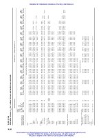
6.4.3 Floor Live Loads
Typical requirements for live loads on floors for different occupancies are summarized in
Table 6.2. These minimum design loads may differ from requirements of local or state
building codes or project specifications. The engineer of record for the building to be con-
structed is responsible for determining the appropriate load requirements.
Temporary or movable partitions should be considered a floor live load. For structures
designed for live loads exceeding 80 lb per ft
2
, however, the effect of partitions may be
ignored, if permitted by the local building code.
Live Load Reduction. Because of the small probability that a member supporting a large
floor area will be subjected to full live loading over the entire area, building codes permit a
reduced live load based on the areas contributing loads to the member (influence area).
Influence area is defined as the floor area over which the influence surface for structural
effects on a member is significantly different from zero. Thus the influence area for an
interior column comprises the four surrounding bays (four times the conventional tributary
area), and the influence area for a corner column is the adjoining corner bay (also four times
the tributary area, or area next to the column and enclosed by the bay center lines). Similarly,
the influence area for a girder is two times the tributary area and equals the panel area for
a two-way slab.
The standard, ‘‘Minimum Design Loads for Buildings and Other Structures’’ (ASCE 7-
95), American Society of Civil Engineers, permits a reduced live load L (lb per ft
2
) computed
from Eq. (6.1) for design of members with an influence area of 400 ft
2
or more:
L ϭ L (0.25 ϩ 15/͙A ) (6.1)
oI
6.4
TABLE 6.1 Minimum Design Dead Loads
Component Load, lb/ft
2
Component Load, lb/ft
2
Component Load, lb/ft
2
Ceilings
Acoustical fiber tile 1
Gypsum board (per
1
⁄
8
-in thickness) 0.55
Mechanical duct allowance 4
Plaster on tile or concrete 5
Plaster on wood lath 8
Suspended steel channel system 2
Suspended metal lath and cement
plaster 15
Suspended metal lath and gypsum
plaster 10
Wood furring suspension system 2.5
Coverings, roof, and wall
Asbestos-cement shingles 4
Asphalt shingles 2
Cement tile 16
Clay tile (for mortar add 10 lb):
Book tile, 2-in 12
Book tile, 3-in 20
Ludowici 10
Waterproofing membranes:
Bituminous, gravel-covered 5.5
Bituminous, smooth surface 1.5
Liquid applied 1.0
Single-ply, sheet 0.7
Wood sheathing (per inch thickness) 3
Wood shingles 3
Floor fill
Cinder concrete, per inch 9
Lightweight concrete, per inch 8
Sand, per inch 8
Stone concrete, per inch 12
Floors and floor finishes
Asphalt block (2-in),
1
⁄
2
-in mortar 30
Cement finish (1-in) on stone-concrete 32
fill
Ceramic or quarry tile (
3
⁄
4
-in) on
1
⁄
2
-in 16
mortar bed
Ceramic or quarry tile (
3
⁄
4
-in) on 1-in 23
mortar bed
Frame partitions
Movable steel partitions 4
Wood or steel studs,
1
⁄
2
-in gypsum board 8
each side
Wood studs, 2
ϫ 4; unplastered 4
Wood studs, 2
ϫ 4, plastered one side 12
Wood studs, 2
ϫ 4, plastered two sides 20
Frame walls
Exterior stud walls:
2
ϫ 4@16in,
5
⁄
8
-in gypsum, insulated, 11
3
⁄
8
-in siding
2
ϫ 6@16in,
5
⁄
8
-in gypsum, insulated, 12
3
⁄
8
-in siding
Exterior stud walls with brick veneer 48
Windows, glass, frame and sash 8
Masonry walls*
Clay brick wythes:
4in 39
8in 79
6.5
TABLE 6.1 Minimum Design Dead Loads
Component Load, lb/ft
2
Component Load, lb/ft
2
Component Load, lb/ft
2
Roman 12
Spanish 19
Composition:
Three-ply ready roofing 1
Four-ply felt and gravel 5.5
Five-ply felt and gravel 6
Copper or tin 1
Deck, metal, 20 ga 2.5
Deck, metal, 18 ga 3
Decking, 2-in wood (Douglas fir) 5
Decking, 3-in wood (Douglas fir) 8
Fiberboard,
1
⁄
2
-in 0.75
Gypsum sheathing,
1
⁄
2
-in 2
Insulation, roof boards (per inch thickness):
Cellular 0.7
Fibrous glass 1.1
Fiberboard 1.5
Perlite 0.8
Polystyrene foam 0.2
Urethane foam with skin 0.5
Plywood (per
1
⁄
8
-in thickness) 0.4
Rigid insulation,
1
⁄
2
-in 0.75
Skylight, metal frame,
3
⁄
8
-in wire glass 8
Slate,
3
⁄
16
-in 7
Slate,
1
⁄
4
-in 10
Concrete fill finish (per inch thicknes) 12
Hardwood flooring,
7
⁄
8
-in 4
Linoleum or asphalt tile,
1
⁄
4
-in 1
Marble and mortar on stone-concrete fill 33
Slate (per inch thickness) 15
Solid flat tile on 1-in mortar base 23
Subflooring,
3
⁄
4
-in 3
Terrazzo (1
1
⁄
2
-in) directly on slab 19
Terrazzo (1-in) on stone-concrete fill 32
Terrazzo (1-in), 2-in stone concrete 32
Wood block (3-in) on mastic, no fill 10
Wood block (3-in) on
1
⁄
2
-in mortar base 16
Floors, wood-joist (no plaster) double wood
floor
Joist
sizes,
in
2 ϫ 6
2
ϫ 8
2
ϫ 10
2
ϫ 12
12-in
spacing,
lb/ft
2
6
6
7
8
16-in
spacing,
lb/ft
2
5
6
6
7
24-in
spacing,
lb/ft
2
5
5
6
6
12 in
16 in
Hollow concrete
masonry unit wythes:
Wythe thickness (in)
Unit percent solid
Light weight units
(105 pcf):
No grout
48 o.c.
40 o.c.
32 o.c. Grout
24 o.c. spacing
·
16 o.c.
Full grout
Normal Weight Units
(135 pcf):
No grout
48 o.c.
40 o.c.
32 o.c. Grout
24 o.c. spacing
·
16 o.c.
Solid concrete masonry
unit wythes (incl.
concrete brick):
Wythe thickness,
Lightweight units
(105 pcf):
Normal weight units
(135 pcf):
4
70
22
29
4
32
41
6
55
27
31
33
34
37
42
57
35
33
36
38
41
47
64
6
49
63
8
52
35
40
43
45
49
56
77
45
50
53
55
59
66
87
8
67
86
10
50
42
49
53
56
61
70
98
54
61
65
68
73
82
110
10
84
108
115
155
12
48
49
58
63
66
72
84
119
63
72
77
80
86
98
133
12
102
131
*Weights of masonry include mortar but not plaster. For plaster, add 5 lb/ ft
2
for each face plastered. Values given
represent averages. In some cases there is a considerable range of weight for the same construction.
Coverings, roof, and wall (cont.)
Floors and floor finishes (cont.)
Masonry walls (cont.)
Clay brick wythes: (cont.)
Clay tile (cont.)
Continued
6.6 SECTION SIX
TABLE 6.2 Minimum Design Live Loads
a. Uniformly distributed design live loads
Occupancy or use
Live load,
lb/ft
2
Occupancy or use
Live load,
lb/ft
2
Armories and drill rooms 150
Assembly areas and theaters
Fixed sets (fastened to floor) 60
Lobbies 100
Movable seats 100
Platforms (assembly) 100
Stage floors 150
Balconies (exterior) 100
On one- and two-family
residences only, and not
exceeding 100 ft
2
60
Bowling alleys, poolrooms, and
similar recreational areas 75
Corridors
First floor 100
Other floors, same as
occupancy served except as
indicated
Dance halls and ballrooms 100
Decks (patio and roof)
Same as area served, or for the
type of occupancy
accommodated
Dining rooms and restaurants 100
Fire escapes 100
On single-family dwellings
only 40
Garages (see Table 6.2b also)
Passenger cars only 50
For trucks and buses use
AASHTO
a
lane loads (see
Table 6.2b also)
Grandstands
c
(see Stadium)
Gymnasiums, main floors and
balconies
c
100
Hospitals (see Table 6.2b also)
Operating room, laboratories 60
Private rooms 40
Wards 40
Corridors above first floor 80
Libraries (see Table 6.2b also)
Reading rooms 60
Stack rooms
d
150
Corridors above first floor 80
Manufacturing (see Table 6.2b
also)
Light 125
Heavy 250
Marquees and canopies 75
Office buildings
b
(see Table 6.2b
also)
Lobbies 100
Offices 50
Penal institutions
Cell blocks 40
Corridors 100
Residential
Dwellings (one- and two-
family)
Uninhabitable attics without
storage 10
Uninhabitable attics with
storage 20
Habitable attics and sleeping
areas 30
All other areas 40
Hotels and multifamily
buildings
Private rooms and corridors
serving them 40
Public rooms, corridors, and
lobbies serving them 100
Schools (see Table 6.2b also)
Classrooms 40
Corridors above first floor 80
Sidewalks, vehicular driveways,
and yards, subject to trucking
a
(see Table 6.2b also) 250
Stadium and arenas
c
100
Bleachers 100
Fixed seats (fastened to floor) 60
Stairs and exitways (see Table
6.2b also) 100
Storage warehouses
Light 125
Heavy 250
Stores
Retail
First floor 100
Upper floors 75
Wholesale, all floors 125
Walkways and elevated platforms
(other than exitways) 60
Yards and terraces (pedestrians) 100
BUILDING DESIGN CRITERIA 6.7
TABLE 6.2
Minimum Design Live Loads (Continued)
b. Concentrated live loads
e
Location Load, lb
Elevator machine room grating (on 4-in
2
area) 300
Finish, light floor-plate construction (on 1-in
2
area) 200
Garages:
Passenger cars:
Manual parking (on 20-in
2
area) 2,000
Mechanical parking (no slab), per wheel 1,500
Trucks, buses (on 20-in
2
area) per wheel 16,000
Hospitals 1000
Libraries 1000
Manufacturing
Light 2000
Heavy 3000
Office floors (on area 2.5 ft square) 2,000
Roof-truss panel point over garage, manufacturing, or storage floors 2,000
Schools 1000
Scuttles, skylight ribs, and accessible ceilings (on area 2.5 ft square) 200
Sidewalks (on area 2.5 ft square) 8,000
Stair treads (on 4-in
2
area at center of tread) 300
c. Minimum design loads for materials
Material
Load,
lb/ft
3
Material
Load,
lb/ft
2
Aluminum, cast 165
Bituminous products:
Asphalt 81
Petroleum, gasoline 42
Pitch 69
Tar 75
Brass, cast 534
Bronze, 8 to 14% tin 509
Cement, portland, loose 90
Cement, portland, set 183
Cinders, dry, in bulk 45
Coal, bituminous or lignite, piled 47
Coal, bituminous or lignite, piled 47
Coal, peat, dry, piled 23
Charcoal 12
Copper 556
Earth (not submerged):
Clay, dry 63
Clay, damp 110
Clay and gravel, dry 100
Silt, moist, loose 78
Silt, moist, packed 96
Earth (not submerged) (Continued ):
Sand and gravel, dry, loose 100
Sand and gravel, dry, packed 120
Sand and gravel, wet 120
Gold, solid 1205
Gravel, dry 104
Gypsum, loose 70
Ice 57.2
Iron, cast 450
Lead 710
Lime, hydrated, loose 32
Lime, hydrated, compacted 45
Magnesium alloys 112
Mortar, hardened:
Cement 130
Lime 110
Riprap (not submerged):
Limestone 83
Sandstone 90
Sand, clean and dry 90
6.8 SECTION SIX
TABLE 6.2 Minimum Design Live Loads (Continued)
c. Minimum Design loads for materials (Continued )
Material
Load,
lb/ft
3
Material
Load,
lb/ft
2
Sand, river, dry 106
Silver 656
Steel 490
Stone, ashlar:
Basalt, granite, gneiss 165
Limestone, marble, quartz 160
Stone, ashlar (Continued ):
Sandstone 140
Shale, slate 155
Tin, cast 459
Water, fresh 62.4
Water, sea 64
a
American Association of State Highway and Transportation Officials lane loads should also be considered where
appropriate.
File and computer rooms should be designed for heavier loads; depending on anticipated installations. See also
corridors.
c
For detailed recommendations, see American National Standard for Assembly Seating, Tents, and Air-Supported
Structures. ANSI/NFPA 102.
d
For the weight of books and shelves, assume a density of 65 pcf, convert it to a uniformly distributed area load,
and use the result if it exceeds 150 lb/ ft
2
.
e
Use instead of uniformly distributed live load, except for roof trusses, if concentrated loads produce greater stresses
or deflections. Add impact factor for machinery and moving loads: 100% for elevators, 20% for light machines, 50%
for reciprocating machines, 33% for floor or balcony hangers. For craneways, add a vertical force equal to 25% of the
maximum wheel load; a lateral force equal to 10% of the weight of trolley and lifted load, at the top of each rail; and
a longitudinal force equal to 10% of maximum wheel loads, acting at top of rail.
where L
o
ϭ unreduced live load, lb per ft
2
A
I
ϭ influence area, ft
2
The reduced live load should not be less than 0.5L
o
for members supporting one floor nor
0.4L
o
for all other loading situations. If live loads exceed 100 lb per ft
2
, and for garages for
passenger cars only, design live loads may be reduced 20% for members supporting more
than one floor. For members supporting garage floors, one-way slabs, roofs, or areas used
for public assembly, no reduction is permitted if the design live load is 100 lb per ft
2
or less.
6.4.4 Concentrated Loads
Some building codes require that members be designed to support a specified concentrated
live load in addition to the uniform live load. The concentrated live load may be assumed
to be uniformly distributed over an area of 2.5 ft
2
and located to produce the maximum
stresses in the members. Table 6.2b lists some typical loads that may be specified in building
codes.
6.4.5 Pattern Loading
This is an arrangement of live loads that produces maximum possible stresses at a point in
a continuous beam. The member carries full dead and live loads, but full live load may
occur only in alternating spans or some combination of spans. In a high-rise building frame,
maximum positive moments are produced by a checkerboard pattern of live load, i.e., by
BUILDING DESIGN CRITERIA 6.9
TABLE 6.3 Roof Live Loads (lb per ft
2
) of Horizontal Projection*
Roof slope
Tributary loaded area, ft
2
, for any
structural member
0 to 200 201 to 600 Over 600
Flat or rise less than 4:12
Arch or dome with rise less
than
1
⁄
8
of span
20 16 12
Rise 4:12 to less than 12:12 16 14 12
Arch or dome with rise
1
⁄
8
span to less than
3
⁄
8
span
Rise 12:12 or greater
Arch or dome with rise
3
⁄
8
of
span or greater
12 12 12
*As specified in ‘‘Low-Rise Building Systems Manual,’’ Metal Building Manu-
facturers Association, Cleveland, Ohio.
full live load on alternate spans horizontally and alternate bays vertically. Maximum negative
moments at a joint occur, for most practical purposes, with full live loads only on the spans
adjoining the joint. Thus pattern loading may produce critical moments in certain members
and should be investigated.
6.5 ROOF LOADS
In northern areas, roof loads are determined by the expected maximum snow loads. However,
in southern areas, where snow accumulation is not a problem, minimum roof live loads are
specified to accommodate the weight of workers, equipment, and materials during mainte-
nance and repair.
6.5.1 Roof Live Loads
Some building codes specify that design of flat, curved, or pitched roofs should take into
account the effects of occupancy and rain loads and be designed for minimum live loads,
such as those given in Table 6.3. Other codes require that structural members in flat, pitched,
or curved roofs be designed for a live load L
r
(lb per ft
2
of horizontal projection) computed
from
L
ϭ 20RR Ն 12 (6.2)
r 12
where R
1
ϭ reduction factor for size of tributary area
ϭ 1 for A
t
Յ 200
ϭ 1.2 Ϫ 0.001A
t
for 200 Ͻ A
t
Ͻ 600
ϭ 0.6 for A
t
Ն 600
A
l
ϭ tributary area, or area contributing load to the structural member, ft
2
(Sec. 6.4.3)
R
2
ϭ reduction factor for slope of roof
ϭ 1 for FՅ 4
6.10 SECTION SIX
ϭ 1.2 Ϫ 0.05F for 4 Ͻ F Ͻ 12
ϭ 0.6 for F Ն 12
F
ϭ rate of rise for a pitched roof, in/ft
ϭ rise-to-span ratio multiplied by 32 for an arch or dome
6.5.2 Snow Loads
Determination of design snow loads for roofs is often based on the maximum ground snow
load in a 50-year mean recurrence period (2% probability of being exceeded in any year).
This load or data for computing it from an extreme-value statistical analysis of weather
records of snow on the ground may be obtained from the local building code or the National
Weather Service. Maps showing ground snow loads for various regions are presented in
model building codes and standards, such as ‘‘Minimum Design Loads for Buildings and
Other Structures’’ (ASCE 7-95), American Society of Civil Engineers. The map scales, how-
ever, may be too small for use for some regions, especially where the amount of local
variation is extreme or high country is involved.
Some building codes and ASCE 7-95 specify an equation that takes into account the
consequences of a structural failure in view of the end use of the building to be constructed
and the wind exposure of the roof:
p
ϭ 0.7CCIp (6.3)
ƒ et g
where C
e
ϭ wind exposure factor (Table 6.4)
C
t
ϭ thermal effects factor (Table 6.6)
I
ϭ importance factor for end use (Table 6.7)
p
ƒ
ϭ roof snow load, lb per ft
2
p
g
ϭ ground snow load for 50-year recurrence period, lb per ft
2
The ‘‘Low-Rise Building systems Manual,’’ Metal Building Manufacturers Association,
Cleveland, Ohio, based on a modified form of ASCE 7, recommends that the design of roof
snow load be determined from
p
ϭ ICp (6.4)
ƒ sg
where I
s
is an importance factor and C reflects the roof type.
In their provisions for roof design, codes and standards also allow for the effect of roof
slopes, snow drifts, and unbalanced snow loads. The structural members should be investi-
gated for the maximum possible stress that the loads might induce.
6.6 WIND LOADS
Wind loads are randomly applied dynamic loads. The intensity of the wind pressure on the
surface of a structure depends on wind velocity, air density, orientation of the structure, area
of contact surface, and shape of the structure. Because of the complexity involved in defining
both the dynamic wind load and the behavior of an indeterminate steel structure when sub-
jected to wind loads, the design criteria adopted by building codes and standards have been
based on the application of an equivalent static wind pressure. This equivalent static design
wind pressure p (psf) is defined in a general sense by
p
ϭ qGC (6.5)
p
where q ϭ velocity pressure, psf
G
ϭ gust response factor to account for fluctuations in wind speed
BUILDING DESIGN CRITERIA 6.11
TABLE 6.4 Exposure Factor, C
e
, for Snow Loads, Eq. (6.3)
Terrain Category
a
Exposure of Roof
a,b
Sheltered
Fully
exposed
Partially
exposed
A N/A 1.1 1.3
B 0.9 1.0 1.2
C 0.9 1.0 1.1
D 0.8 0.9 1.0
Above the treeline in windswept
mountainous areas.
0.7 0.8 N/A
Alaska, in areas where trees do not
exist within a 2-mile radius of site
0.7 0.8 N/A
a
See Table 6.5 for definition of categories. The terrain category and roof exposure
condition chosen should be representative of the anticipated conditions during the life
of the structure.
b
The following definitions apply: Fully Exposed, roofs exposed on all sides with
no shelter
c
afforded by terrain, higher structures or trees, excluding roofs that contain
several large pieces of mechanical equipment or other obstructions; Partially Exposed,
all roofs except for fully exposed and sheltered; Sheltered, roofs located tight in among
conifers that qualify as obstructions.
c
Obstructions within a distance of 10 h
e
provide shelter, where h
e
is the height of
the obstruction above the roof level. If the only obstructions are a few deciduous trees
that are leafless in winter, the fully exposed category should be used except for terrain
category ‘‘A.’’ Although heights above roof level are used here, heights above ground
are used n defining exposure categories.
Source: Adapted from Minimum Design Loads for Buildings and Other Struc-
tures, (ASCE 7-95), American Society of Civil Engineers, Reston, Va.
TABLE 6.5 Definition of Exposure Categories
Terrain category Definition
A Large city centers with at least 50% of buildings hav-
ing height in excess of 70 ft
B Urban and suburban areas, wooded areas or terrain
with numerous closely spaced obstructions having size
of single-family dwellings or larger
C Open terrain with scattered obstructions having heights
generally
Ͻ30 ft, including flat open country, grass-
lands and shorelines in hurricane prone regions
D Flat, unobstructed areas exposed to wind flowing over
open water for a distance of at least one mile, exclud-
ing shorelines in hurricane prone regions
Source: Adapted from Minimum Design Loads for Buildings and Other Structures,
(ASCE 7-95), American Society of Civil Engineers, Reston, Va.
6.12 SECTION SIX
TABLE 6.6 Thermal Factor for Eq. (6.3)
Thermal condition*
Thermal
factor C
l
Heated structure 1.0
Structure kept just above freezing 1.1
Unheated structure 1.2
*These conditions should be representative of those
which are likely to exist during the life of the structure.
TABLE 6.7 Importance Factor for
Snowloads, Eq. (6.3)
Category* Importance factor I
I 0.8
II 1.0
III 1.1
IV 1.2
*See Table 6.8 for description of categories.
C
p
ϭ pressure coefficient or shape factor that reflects the influence of the wind on the
various parts of a structure
The ASCE 7-95 wind load provisions incorporated significant changes to the determi-
nation of design wind loads. Most significant changes were: (1) a new Wind Speed Map
based on 3-second gust speeds, (2) new provisions for wind speed-up due to topographical
effects, (3) substantial increases in internal pressure coefficients for low-rise buildings in
hurricane zones, (4) decreases in design wind pressures for low-rise buildings in suburban
terrain, and (5) two separate methods for assessing wind loads for buildings having heights
less than 60 ft. The ASCE 7-98 (draft) has proposed important additional refinements to the
ASCE 7-95 provisions, which should be referred to.
Velocity pressure is computed from
2
q ϭ 0.00256 KK KVI (6.6)
zzztd
where K
z
ϭ velocity exposure coefficient evaluated at height z
K
zt
ϭ topographic factor
K
d
ϭ wind directionality factor
I
ϭ importance factor
V
ϭ basic wind speed corresponding to a 3-second gust speed at 33 ft above the
ground in exposure C
Velocity pressures due to wind to be used in building design vary with type of terrain,
distance above ground level, importance of building, likelihood of hurricanes, and basic wind
speed recorded near the building site. The wind pressures are assumed to act horizontally
on the building area projected on a vertical plane normal to the wind direction.
Unusual wind conditions often occur over rough terrain and around ocean promontories.
Basic wind speeds applicable to such regions should be selected with the aid of meteorol-
BUILDING DESIGN CRITERIA 6.13
TABLE 6.8 Classifications for Wind, Snow, and Earthquake Loads
Nature of occupancy Category
Buildings and other structures that represent a low hazard to human life in the
event of failure including, but not limited to:
Agricultural facilities
Certain temporary facilities
Minor storage facilities
I
All buildings and other structures except those listed in Categories I, III, and
IV
II
Buildings and other structures that represent a substantial hazard to human
life in the event of failure including, but not limited to:
III
Buildings and other structures where more than 300 people congregate in one area
Buildings and other structures with elementary school, secondary school, or day-care facilities with
capacity greater than 250
Buildings and other structures with a capacity greater than 500 for colleges or adult education facil-
ities
Health-care facilities with a capacity of 50 or more resident patients but not having surgery or
emergency treatment facilities
Jails and detention facilities
Power generating stations and other public utility facilities not included in Category IV
Buildings and other structures containing sufficient quantities of toxic or explosive substances to be
dangerous to the public if released
Buildings and other structures designated as essential facilities including, but
not limited to:
IV
Hospitals and other health-care facilities having surgery or emergency treatment facilities
Fire, rescue and police stations and emergency vehicle garages
Designated earthquake, hurricane, or other emergency shelters
Communications centers and other facilities required for emergency response
Power generating stations and other public utility facilities required in an emergency
Buildings and other structures having critical national defense functions
Source: From Minimum Design Loads for Buildings and Other Structures, (ASCE 7-95), American Society of
Civil Engineers, Reston, Va., with permission.
ogists and the application of extreme-value statistical analysis to anemometer readings taken
at or near the site of the proposed building. Generally, however, minimum basic wind ve-
locities are specified in local building codes and in national model building codes but should
be used with discretion, because actual velocities at a specific site and on a specific building
may be significantly larger. In the absence of code specifications and reliable data, basic
wind speed at a height of 10 m above grade may be estimated from Fig. 6.1.
For design purposes, wind pressures should be determined in accordance with the degree
to which terrain surrounding the proposed building exposes it to the wind. Exposures are
defined in Table 6.5.
ASCE 7 permits the use of either Method I or Method II to define the design wind loads.
Method I is a simplified procedure and may be used for enclosed or partially enclosed
buildings meeting the following conditions:
6.14
FIGURE 6.1 Contours on map of the United States show basic wind speeds (fastest-mile speeds recorded
10 m above ground) for open terrain and grasslands with 50-year mean recurrence interval. (Source: ‘‘Minimum
Design Loads for Buildings and Other Structures,’’ ASCE 7-95, American Society of Civil Engineers, Reston,
Va., with permission.)
BUILDING DESIGN CRITERIA 6.15
TABLE 6.9 Importance Factor for Wind Loads, Eq. (6.6)
Category* V ϭ 85–100 mph
Importance factor, I
hurricane prone regions,
V
Ͼ 100 mph
I 0.87 0.77
II 1.00 1.00
III 1.15 1.15
IV 1.15 1.15
*See Table 6.8 for description of categories.
Source: From Minimum Design Loads for Buildings and Other
Structures, (ASCE 7-95), American Society of Civil Engineers, Reston,
Va., with permission.
1. building in which the wind loads are transmitted through floor and roof diaphragms to
the vertical main wind force resisting system
2. building has roof slopes less than 10
Њ
3. mean roof height is less than or equal to 30 ft.
4. building having no unusual geometrical irregularity in spatial form
5. building whose fundamental frequency is greater than 1 hz
6. building structure having no expansion joints or separations
7. building is not subject to topographical effects.
The design procedure for Method I involves the following considerations:
1. Determine the basic design speed, V, from Fig. 6.1
2. Select the importance factor, I, using Table 6.9
3. Define the exposure category, i.e., A, B, C, or D, using Table 6.5
4. Define the building enclosure classification, i.e., enclosed or partially enclosed
5. Using Table 6.10, determine the design wind load for the main wind force resisting system
6. Using Table 6.11 or 6.12 determine the design wind load for the component and cladding
elements.
ASCE 7 Method II is a rigorous computation procedure that accounts for the external,
and internal pressure variation as well as gust effects. The following is the general equation
for computing the design wind pressure, p:
p
ϭ qGC Ϫ q (GC ) (6.7)
pipi
where q and q
i
ϭ velocity pressure as given by ASCE 7
G
ϭ gust effect factor as given by ASCE 7
C
p
ϭ external pressure coefficient as given by ASCE 7
GC
pi
ϭ internal pressure coefficient as given by ASCE 7
Codes and standards may present the gust factors and pressure coefficients in different
formats. Coefficients from different codes and standards should not be mixed.
Designers should exercise judgment in selecting wind loads for a building with unusual
shape, response-to-load characteristics, or site exposure where channeling of wind currents
6.16 SECTION SIX
TABLE 6.10 Design Wind Pressure-Method 1 Simplified Procedure Main Wind-Force Resisting System
DESIGN WIND PRESSURE (PSF)
Basic Wind Speed V (MPH)
Location
Building
classification 85
90 100 110 120 130 140 150 160 170
Roof
Enclosed
Partially enclosed
Ϫ14
Ϫ19
Ϫ16
Ϫ21
Ϫ20
Ϫ26
Ϫ24
Ϫ31
Ϫ29
Ϫ37
Ϫ33
Ϫ44
Ϫ39
Ϫ51
Ϫ45
Ϫ58
Ϫ51
Ϫ66
Ϫ57
Ϫ74
Wall
Enclosed or
partially enclosed
12 14 17 20 24 29 33 38 43 49
1
Design wind pressures above represent the following:
Roof—Net pressure (sum of external and internal pressures) applied normal to all roof surfaces.
Wall—combined net pressure (sum of windward and leeward, external and internal pressures) applied normal to all windward wall surfaces.
2
Values shown are for exposure B. For other exposures, multiply values shown by the factor below:
Exposure Factor
C 1.40
D 1.66
3
Values shown for roof are based on a tributary area less than or equal to 100 sf. For larger tributary areas, multiply
values shown by reduction factor below:
Area
(SF)
Reduction Factor (Linear inter-
polation permitted)
Յ100 1.0
250 0.9
Ն1000 0.8
4
Values shown are for importance factor I ϭ 1.0. for other values of I, multiply values showed by I.
5
Plus and minus signs indicate pressures acting toward and away from exterior surface, respectively.
Source: From Minimum Design Loads for Buildings and Other Structures, (ASCE 7-95), American Society of
Civil Engineers, Reston, Va., with permission.
or buffeting in the wake of upwind obstructions should be considered in design. Wind-tunnel
tests on a model of the structure and its neighborhood may be helpful in supplying design
data. (See also Sec. 9.)
(‘‘Minimum Design Loads for Buildings and Other Structures,’’ ASCE 7-95; and K. C.
Mehta et al., Guide to the Use of the Wind Load Provisions, American Society of Civil
Engineers.)
6.17
TABLE 6.11 Design Wind Pressure—Method 1 Components and Cladding—Enclosed Building
DESIGN WIND PRESSURE (PSF)
Location Zone
Effective
wind
area
(SF)
Basic wind speed V (mph)
85 90 100 110 120 130 140 150 160 170
10 ϩ5 Ϫ13 ϩ6 Ϫ15 ϩ7 Ϫ18 ϩ9 Ϫ22 ϩ11 Ϫ26 ϩ12 Ϫ30 ϩ14 Ϫ35 ϩ16 Ϫ40 ϩ19 Ϫ46 ϩ21 Ϫ52
120ϩ5 Ϫ13 ϩ6 Ϫ14 ϩ7 Ϫ18 ϩ8 Ϫ21 ϩ10 Ϫ25 ϩ12 Ϫ30 ϩ13 Ϫ34 ϩ15 Ϫ39 ϩ18 Ϫ45 ϩ20 Ϫ51
100 ϩ4 Ϫ12 ϩ5 Ϫ13 ϩ6 Ϫ16 ϩ7 Ϫ20 ϩ8 Ϫ24 ϩ10 Ϫ28 ϩ11 Ϫ32 ϩ13 Ϫ37 ϩ15 Ϫ42 ϩ17 Ϫ48
6.18
TABLE 6.11 Design Wind Pressure—Method 1 Components and Cladding—Enclosed Building (Continued )
DESIGN WIND PRESSURE (PSF)
Location Zone
Effective
wind
area
(SF)
Basic wind speed V (mph)
85 90 100 110 120 130 140 150 160 170
10 ϩ5 Ϫ22 ϩ6 Ϫ24 ϩ7 Ϫ30 ϩ9 Ϫ36 ϩ11 Ϫ43 ϩ12 Ϫ51 ϩ14 Ϫ59 ϩ16 Ϫ68 ϩ19 Ϫ77 ϩ21 Ϫ87
Roof 2 20 ϩ5 Ϫ19 ϩ6 Ϫ22 ϩ7 Ϫ27 ϩ8 Ϫ33 ϩ10 Ϫ39 ϩ12 Ϫ46 ϩ13 Ϫ53 ϩ15 Ϫ61 ϩ18 Ϫ69 ϩ20 Ϫ78
100 ϩ4 Ϫ14 ϩ5 Ϫ16 ϩ6 Ϫ19 ϩ7 Ϫ24 ϩ8 Ϫ28 ϩ10 Ϫ33 ϩ11 Ϫ38 ϩ13 Ϫ44 ϩ15 Ϫ50 ϩ17 Ϫ56
10 ϩ5 Ϫ33 ϩ6 Ϫ37 ϩ7 Ϫ45 ϩ9 Ϫ55 ϩ11 Ϫ65 ϩ12 Ϫ77 ϩ14 Ϫ89 ϩ16 Ϫ102 ϩ19 Ϫ116 ϩ21 Ϫ131
320ϩ5 Ϫ27 ϩ6 Ϫ30 ϩ7 Ϫ37 ϩ8 Ϫ45 ϩ10 Ϫ54 ϩ12 Ϫ63 ϩ13 Ϫ73 ϩ15 Ϫ84 ϩ18 Ϫ96 ϩ20 Ϫ108
100 ϩ4 Ϫ14 ϩ5 Ϫ16 ϩ6 Ϫ19 ϩ7 Ϫ24 ϩ8 Ϫ28 ϩ10 Ϫ33 ϩ11 Ϫ38 ϩ13 Ϫ44 ϩ15 Ϫ50 ϩ17 Ϫ56
10 ϩ13 Ϫ14 ϩ15 Ϫ16 ϩ18 Ϫ19 ϩ22 Ϫ24 ϩ26 Ϫ28 ϩ30 Ϫ33 ϩ35 Ϫ38 ϩ40 Ϫ44 ϩ46 Ϫ50 ϩ52 Ϫ56
450ϩ12 Ϫ13 ϩ13 Ϫ14 ϩ16 Ϫ18 ϩ19 Ϫ22 ϩ23 Ϫ26 ϩ27 Ϫ30 ϩ31 Ϫ35 ϩ36 Ϫ40 ϩ41 Ϫ46 ϩ46 Ϫ51
500 ϩ10 Ϫ11 ϩ11 Ϫ12 ϩ13 Ϫ15 ϩ16 Ϫ18 ϩ19 Ϫ21 ϩ23 Ϫ25 ϩ26 Ϫ29 ϩ30 Ϫ34 ϩ34 Ϫ38 ϩ39 Ϫ43
Walls 10 ϩ13 Ϫ17 ϩ15 Ϫ19 ϩ18 Ϫ24 ϩ22 Ϫ29 ϩ26 Ϫ35 ϩ30 Ϫ41 ϩ35 Ϫ47 ϩ40 Ϫ54 ϩ46 Ϫ62 ϩ52 Ϫ70
550ϩ12 Ϫ15 ϩ13 Ϫ16 ϩ16 Ϫ20 ϩ19 Ϫ25 ϩ23 Ϫ29 ϩ27 Ϫ34 ϩ31 Ϫ40 ϩ36 Ϫ46 ϩ41 Ϫ52 ϩ46 Ϫ59
500 ϩ10 Ϫ11 ϩ11 Ϫ12 ϩ13 Ϫ15 ϩ16 Ϫ18 ϩ19 Ϫ21 ϩ23 Ϫ25 ϩ26 Ϫ29 ϩ30 Ϫ34 ϩ34 Ϫ38 ϩ39 Ϫ43
1
Design wind pressures above represent the net pressure (sum of external and internal pressures) applied normal to all surfaces.
2
Values shown are for exposure B. For other exposures, multiply values shown by the following factor: exposure C: 1.40 and exposure D: 1.66.
3
Linear interpolation between values of tributary area is permissible.
4
Values shown are for an importance factor I ϭ 1.0. for other values of I, multiply values shown by I.
5
Plus and minus signs signify pressure acting toward and away from the exterior surface, respectively.
6
All component and cladding elements shall be designed for both positive and negative pressures shown in the table.
7
Notation:
a: 10% of least horizontal or 0.4 h, whichever is smaller, but not less than 4% of least horizontal dimension or 3 ft.
b: Roof height in feet (meters).
Source: From Minimum Design Loads for Buildings and Other Structures (ASCE 7-95), American Society of Civil Engineers, Reston, Va., with permission.
6.19
TABLE 6.12 Design Wind Pressure—Method 1 Components and Cladding—Partially Enclosed Building
DESIGN WIND PRESSURE (PSF)
Location Zone
Effective
wind
area
(SF)
Basic wind speed V (mph)
85 90 100 110 120 130 140 150 160 170
10 ϩ9 Ϫ17 ϩ10 Ϫ19 ϩ13 Ϫ24 ϩ16 Ϫ29 ϩ19 Ϫ34 ϩ22 Ϫ40 ϩ25 Ϫ46 ϩ29 Ϫ53 ϩ33 Ϫ60 ϩ37 Ϫ68
Roof 1 20 ϩ9 Ϫ17 ϩ10 Ϫ19 ϩ12 Ϫ23 ϩ15 Ϫ28 ϩ18 Ϫ33 ϩ21 Ϫ39 ϩ24 Ϫ45 ϩ28 Ϫ52 ϩ32 Ϫ59 ϩ36 Ϫ67
100 ϩ8 Ϫ16 ϩ9 Ϫ18 ϩ11 Ϫ22 ϩ14 Ϫ27 ϩ16 Ϫ32 ϩ19 Ϫ37 ϩ22 Ϫ43 ϩ26 Ϫ50 ϩ29 Ϫ57 ϩ33 Ϫ64
6.20
TABLE 6.12 Design Wind Pressure—Method 1 Components and Cladding—Partially Enclosed Building (Continued )
DESIGN WIND PRESSURE (PSF)
Location Zone
Effective
wind
area
(SF)
Basic wind speed V (mph)
85 90 100 110 120 130 140 150 160 170
10 ϩ9 Ϫ26 ϩ10 Ϫ29 ϩ13 Ϫ36 ϩ16 Ϫ43 ϩ19 Ϫ52 ϩ22 Ϫ60 ϩ25 Ϫ70 ϩ29 Ϫ81 ϩ33 Ϫ92 ϩ37 Ϫ103
Roof 2 20 ϩ9 Ϫ24 ϩ10 Ϫ26 ϩ12 Ϫ33 ϩ15 Ϫ39 ϩ18 Ϫ47 ϩ21 Ϫ55 ϩ24 Ϫ64 ϩ28 Ϫ73 ϩ32 Ϫ83 ϩ36 Ϫ94
100 ϩ8 Ϫ18 ϩ9 Ϫ20 ϩ11 Ϫ25 ϩ14 Ϫ30 ϩ16 Ϫ36 ϩ19 Ϫ42 ϩ22 Ϫ49 ϩ26 Ϫ57 ϩ29 Ϫ64 ϩ33 Ϫ73
10 ϩ9 Ϫ37 ϩ10 Ϫ41 ϩ13 Ϫ51 ϩ16 Ϫ62 ϩ19 Ϫ73 ϩ22 Ϫ86 ϩ25 Ϫ100 ϩ29 Ϫ115 ϩ33 Ϫ131 ϩ37 Ϫ147
320ϩ9 Ϫ31 ϩ10 Ϫ35 ϩ12 Ϫ43 ϩ15 Ϫ52 ϩ18 Ϫ62 ϩ21 Ϫ73 ϩ24 Ϫ84 ϩ28 Ϫ97 ϩ32 Ϫ110 ϩ36 Ϫ125
100 ϩ8 Ϫ18 ϩ9 Ϫ20 ϩ11 Ϫ25 ϩ14 Ϫ30 ϩ16 Ϫ36 ϩ19 Ϫ42 ϩ22 Ϫ49 ϩ26 Ϫ57 ϩ29 Ϫ64 ϩ33 Ϫ73
10 ϩ17 Ϫ18 ϩ19 Ϫ20 ϩ24 Ϫ25 ϩ29 Ϫ30 ϩ34 Ϫ36 ϩ40 Ϫ42 ϩ46 Ϫ49 ϩ53 Ϫ57 ϩ60 Ϫ64 ϩ68 Ϫ73
450ϩ16 Ϫ17 ϩ18 Ϫ19 ϩ22 Ϫ23 ϩ26 Ϫ28 ϩ31 Ϫ34 ϩ37 Ϫ40 ϩ42 Ϫ46 ϩ49 Ϫ53 ϩ55 Ϫ60 ϩ63 Ϫ68
500 ϩ14 Ϫ15 ϩ15 Ϫ17 ϩ19 Ϫ21 ϩ23 Ϫ25 ϩ27 Ϫ30 ϩ32 Ϫ35 ϩ37 Ϫ40 ϩ43 Ϫ46 ϩ49 Ϫ53 ϩ55 Ϫ59
Walls
10
ϩ17 Ϫ21 ϩ19 Ϫ24 ϩ24 Ϫ30 ϩ29 Ϫ36 ϩ34 Ϫ43 ϩ40 Ϫ50 ϩ46 Ϫ58 ϩ53 Ϫ67 ϩ60 Ϫ76 ϩ68 Ϫ86
550ϩ16 Ϫ19 ϩ18 Ϫ21 ϩ22 Ϫ26 ϩ26 Ϫ31 ϩ31 Ϫ37 ϩ37 Ϫ44 ϩ42 Ϫ51 ϩ49 Ϫ58 ϩ55 Ϫ66 ϩ63 Ϫ75
500 ϩ14 Ϫ15 ϩ15 Ϫ17 ϩ19 Ϫ21 ϩ23 Ϫ25 ϩ27 Ϫ30 ϩ32 Ϫ35 ϩ37 Ϫ40 ϩ43 Ϫ46 ϩ49 Ϫ53 ϩ55 Ϫ59
Notes:
1. Design wind pressures above represent the net pressure (sum of external and internal pressures) applied normal to all surfaces.
2. Values shown are for exposure B. For other exposures, multiply values shown by the following factor: exposure C: 1.40 and exposure D: 1.66.
3. Linear interpolation between values of tributary area is permissible.
4. Values shown are for an importance factor I
ϭ 1.0. For other values of I, multiply values shown by I.
5. Plus and minus signs signify pressure acting toward and away from the exterior surface, respectively.
6. All component and cladding elements shall be designed for both positive and negative pressures shown in the table.
7. Notation:
a: 10% of least horizontal or 0.4 h, whichever is smaller, but not less than 4% of least horizontal dimension or 3 ft
h: Roof height in feet (meters).
Source: From Minimum Design Loads for Buildings and Other Structures (ASCE 7-95), American Society of Civil Engineers, Reston, Va., with permission.
BUILDING DESIGN CRITERIA 6.21
6.7 SEISMIC LOADS
Earthquakes have occurred in many states. Figures 6.2 and 6.3 show contour maps of the
United States that reflect the severity of seismic accelerations, as indicated in ‘‘Minimum
Design Loads for Buildings and Other Structures’’ (ASCE 7-95), American Society of Civil
Engineers.
The engineering approach to seismic design differs from that for other load types. For
live, wind, or snow loads, the intent of a structural design is to preclude structural damage.
However, to achieve an economical seismic design, codes and standards permit local yielding
of a structure during a major earthquake. Local yielding absorbs energy but results in per-
manent deformations of structures. Thus seismic design incorporates not only application of
anticipated seismic forces but also use of structural details that ensure adequate ductility to
absorb the seismic forces without compromising the stability of structures. Provisions for
this are included in the AISC specifications for structural steel for buildings.
The forces transmitted by an earthquake to a structure result from vibratory excitation of
the ground. The vibration has both vertical and horizontal components. However, it is cus-
tomary for building design to neglect the vertical component because most structures have
reserve strength in the vertical direction due to gravity-load design requirements.
Seismic requirements in building codes and standards attempt to translate the complicated
dynamic phenomenon of earthquake force into a simplified equivalent static force to be
applied to a structure for design purposes. For example, ASCE 7-95 stipulates that the total
lateral force, or base shear, V (kips) acting in the direction of each of the principal axes of
the main structural system should be computed from
V
ϭ CW (6.8)
s
where C
s
ϭ seismic response coefficient
W
ϭ total dead load and applicable portions of other loads.
Applicable portions of other loads are considered to be as follows:
1. In areas for storage, a minimum of 25% of the floor live load is applicable. The 50 psf
floor live load for passenger cars in parking garages need not be considered.
2. Where an allowance for partition load is included in the floor load design, the actual
partition weight or a minimum weight of 10 psf of floor area, whichever is greater, is
applicable.
3. Total operating weight of permanent equipment.
4. Where the flat roof snow load exceeds 30 psf, the design snow load should be included
in W. Where the authority having jurisdiction approves, the amount of snow load included
in W may be reduced to no less than 20% of the design snow load.
The seismic coefficient, C
s
, is determined by the following equation:
2/3
C ϭ 1.2C /RT (6.9)
s
v
where C
v
ϭ seismic coefficient for acceleration dependent (short period) structures
R
ϭ response modification factor
T
ϭ fundamental period, s
Alternatively, C
s
need not be greater than:
C
ϭ 2.5C /R (6.10)
sa
where C
a
ϭ seismic coefficient for velocity dependent (intermediate and long period) struc-
tures.
6.22
FIGURE 6.2 Contour map of the United States showing effective peak acceleration, A
a
.(Source: From
Minimum Design Loads for Buildings and Other Structures, ASCE 7-95, American Society of Civil Engineers,
Reston, Va., with permission.)
BUILDING DESIGN CRITERIA 6.23
TABLE 6.13
Soil Profile Descriptions for Seismic Analysis
Soil
Profile
Type* Description**
A Hard rock with Ͼ 5000 ft/secv
s
B Rock with 2500 ft/sec Ͻ Յ 5000 ft/secv
s
C Very dense soil and soft rock with 1200 ft/sec ՅՅ5000 ft/sec or or Ͼ 50 orv NN
sch
Ն 2000 psfs
u
D Stiff soil with 600 ft/sec ՅՅ1200 ft/sec or with 15 Յ or Յ 50 or 1000 psfv NN
sch
ՅՅ2000 psfs
u
E A soil profile with Ͻ 600 ft/sec or any profile with more than 10 ft of soft clay. Softv
s
clay is defined as soil with PI Ͼ 20, w Ն 40%, and Ͻ 500 psfs
u
F Soils requiring site-specific evaluations:
1. Soils vulnerable to potential failure or collapse under seismic loading such as
liquefiable soils, quick and highly sensitive clays, collapsible weakly cemented soils.
2. Peats and/or highly organic clays (soil thickness
Ͼ 10 ft of peat, and/or highly
organic clay).
3. Very high plasticity clays (soil thickness
Ͼ 25 ft with PI Ͼ 75).
4. Very thick soft/medium stiff clays (soil thickness
Ͼ 120 ft).
*Exception: When the soil properties are not known in sufficient detail to determine the Soil Profile Type, Type D
should be used. Soil Profile Type E should be used when the authority having jurisdiction determines that soil Profile
Type E is present at the site or in the event that Type E is established by geotechnical data.
**The following definitions apply, where the bar denotes average value for the top 100 ft of soil. See ASCE 7-95
for specific details.
v ϭ measured shear wave velocity, ft/sec;
s
N ϭ standard penetration resistance, blows/ft
N
ϭ corrected for cohesionless layers, blows /ft
ch
s ϭ undrained shear strength, ft/sec
u
PI ϭ plasticity index
w
ϭ liquid limit
Source: Adapted from Minimum Design Loads for Buildings and Other Structures, (ASCE 7-95), American So-
ciety of Civil Engineers, Reston, Va.
Coefficients C
V
and C
a
are based on the soil profile and are determined as follows. From
the descriptions in Table 6.13, determine the soil profile type for the site under consideration.
From Fig. 6.2, determine the effective peak acceleration, A
a
. Enter Tables 6.14 and 6.15
with A
a
and the soil type to find coefficients C
V
and C
a
. For the cases noted in Table 6.14,
C
V
depends upon the effective peak velocity-related acceleration, A
V
, Fig. 6.3.
The response modification factor, R, depends upon the structural bracing system used as
detailed in Table 6.15. The higher the factor, the more energy the system can absorb and
hence the lower the design force. For example, ordinary moment frames are assigned a factor
of 3 and special moment frames a factor of 8 (see Art. 9.7.1). Note that the forces resulting
from the application of these R factors are intended to be used in LRFD design, not at an
allowable stress level (see Art. 6.12).
A rigorous evaluation of the fundamental elastic period, T, requires consideration of the
intensity of loading and the response of the structure to the loading. To expedite design
computations, T may be determined by the following:
3/4
T ϭ Ch (6.11)
aTn
6.24 SECTION SIX
TABLE 6.14 Seismic Coefficient C
v
Soil
profile
type
Shaking intensity
A
s
Ͻ 0.05g A
a
ϭ 0.05g A
a
ϭ 0.10g A
a
ϭ 0.20g A
a
ϭ 0.30g A
a
ϭ 0.40g A
a
Ն 0.5g
b
A A
v
0.04 0.08 0.16 0.24 0.32 0.40
B A
v
0.05 0.10 0.20 0.30 0.40 0.50
C A
v
0.09 0.17 0.32 0.45 0.56 0.65
D A
v
0.12 0.24 0.40 0.54 0.64 0.75
E A
v
0.18 0.35 0.64 0.84 0.96
a
NOTE: For intermediate values, the higher value or straight-line interpolation shall be used to determine the value of C
v
.
a
Site specific geotechnical investigation and dynamic site response analyses shall be performed.
b
Site specific studies required per Section 9.2.2.4.3 (ASCE 7-95) may result in higher values of A
v
than included on the hazard maps,
as may the provisions of Section 9.2.6 (ASCE 7-95).
Source: From Minimum Design Loads for Buildings and Other Structures. (ASCE 7-95), American Society of Civil Engineers, Reston,
Va., with permission.
TABLE 6.15 Seismic Coefficient C
a
Soil
profile
type
Shaking intensity
A
s
Ͻ 0.05g A
a
ϭ 0.05g A
a
ϭ 0.10g A
a
ϭ 0.20g A
a
ϭ 0.30g A
a
ϭ 0.40g A
a
Ն 0.5g
b
A A
a
0.04 0.08 0.16 0.24 0.32 0.40
B A
a
0.05 0.10 0.20 0.30 0.40 0.50
C A
a
0.06 0.12 0.24 0.33 0.40 0.50
D A
a
0.08 0.16 0.28 0.36 0.44 0.50
E A
a
0.13 0.25 0.34 0.36 0.36
a
NOTE: For intermediate values, the higher value or straight-line interpolation shall be used to determine the value of C
a
.
a
Site specific geotechnical investigation and dynamic site response analyses shall be performed.
b
Site specific studies required per Section 9.2.2.4.3 (ASCE 7-95) may result in higher values of A
a
than included on the hazard maps,
as may the provisions of Section 9.2.6 (ASCE 7-95).
Source: From Minimum Design Loads for Buildings and Other Structures. (ASCE 7-95), American Society of Civil Engineers, Reston,
Va., with permission.
where C
T
ϭ 0.035 for steel frames
C
T
ϭ 0.030 for reinforced concrete frames
C
T
ϭ 0.030 steel eccentrically braced frames
C
T
ϭ 0.020 all other buildings
h
n
ϭ height above the base to the highest level of the building, ft
For vertical distribution of seismic forces, the lateral force, V, should be distributed over
the height of the structure as concentrated loads at each floor level or story. The lateral
seismic force, F
x
, at any floor level is determined by the following equation:
F
ϭ CV (6.12a)
x
v
x
where the vertical distribution factor is given by
k
wh
xx
C ϭ (6.12b)
v
x
nk
͚ wh
i
ϭ
1 ii
6.25
FIGURE 6.3 Contour map of the United States showing effective peak velocity-related acceleration, A
V
.
(Source: From Minimum Design Loads for Buildings and Other Structures, ASCE 7-95, American Society of
Civil Engineers, Reston, Va., with permission.)