NTN, BALL AND ROLLER BEARING CATALOG Part 7 ppsx
Bạn đang xem bản rút gọn của tài liệu. Xem và tải ngay bản đầy đủ của tài liệu tại đây (735.5 KB, 30 trang )
Constant
Axial load factors Mass
kg
cylindrical bore tapered bore
eY
1
Y
2
Y
o
(approx.)
B-79
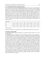
●Self-Aligning Ball Bearings
Fa
Fr
XY X
Y
≦e
F
a
Fr
>e
P
r=XFr+YFa
Por=Fr+Yo Fa
For values of e,Y1,Y2 and Yo
see the table below.
1 Y1 0.65 Y2
Equivalent bearing load
dynamic
static
0.32 2 3.09 2.09 0.033
―
0.64 0.98 1.52 1.03 0.047
―
0.34 1.85 2.87 1.94 0.058
―
0.67 0.95 1.46 0.99 0.083
―
0.36 1.76 2.73 1.85 0.04
―
0.58 1.09 1.69 1.14 0.051
―
0.33 1.91 2.95 2 0.066
―
0.61 1.03 1.59 1.08 0.091
―
0.33 1.91 2.95 2 0.049
―
0.50 1.25 1.94 1.31 0.06
―
0.34 1.86 2.88 1.95 0.092
―
0.52 1.22 1.88 1.27 0.114
―
0.31 2.03 3.14 2.12 0.072
―
0.51 1.23 1.90 1.29 0.088
―
0.32 1.97 3.06 2.07 0.128
―
0.52 1.22 1.88 1.28 0.156
―
0.29 2.2 3.4 2.3 0.116 0.114
0.49 1.3 2.01 1.36 0.14 0.137
0.29 2.16 3.34 2.26 0.16 0.158
0.51 1.23 1.9 1.29 0.206 0.201
0.28 2.28 3.53 2.39 0.138 0.135
0.41 1.55 2.39 1.62 0.157 0.153
0.28 2.28 3.53 2.39 0.255 0.251
0.48 1.32 2.05 1.39 0.334 0.326
0.25 2.55 3.94 2.67 0.217 0.213
0.38 1.64 2.53 1.72 0.256 0.25
0.26 2.40 3.72 2.52 0.383 0.377
0.44 1.42 2.2 1.49 0.496 0.485
0.23 2.71 4.2 2.84 0.317 0.312
0.37 1.69 2.61 1.77 0.392 0.382
0.25 2.48 3.84 2.60 0.5 0.492
0.46 1.37 2.13 1.44 0.671 0.653
1 Smallest allowable dimension for chamfer dimension r. 2 "K" indicates bearings have tapered bore with a taper ratio of 1: 12.
B-80
●Self-Aligning Ball Bearings
Boundary dimensions Basic load ratings Limiting speeds Bearing numbers Abutment and
dynamic static dynamic static
fillet dimensions
mm kN kgf rpm mm
cylindrical tapered
2
d
a
D
a
r
as
dD Br
s min
1
C
r
C
or
C
r
C
or
grease oil
bore bore
min max max
40
45
50
55
60
65
70
75
d 40∼75mm
80 18 1.1 19.3 6.55 1,970 665 7,100 8,400
1208 1208K
46.5 73.5 1
80 23 1.1 22.3 7.35 2,270 750 6,700 7,900
2208 2208K
46.5 73.5 1
90 23 1.5 29.6 9.70 3,000 990 6,000 7,000
1308 1308K
48 82 1.5
90 33 1.5 45.0 13.5 4,600 1,380 5,600 6,600
2308 2308K
48 82 1.5
85 19 1.1 21.9 7.35 2,230 750 6,400 7,500
1209 1209K
51.5 78.5 1
85 23 1.1 23.2 8.15 2,360 830 6,000 7,100
2209 2209K
51.5 78.5 1
100 25 1.5 38.0 12.7 3,900 1,300 5,400 6,300
1309 1309K
53 92 1.5
100 36 1.5 54.0 16.7 5,500 1,700 5,000 5,900
2309 2309K
53 92 1.5
90 20 1.1 22.7 8.10 2,320 830 5,800 6,800
1210 1210K
56.5 83.5 1
90 23 1.1 23.2 8.45 2,370 865 5,500 6,400
2210 2210K
56.5 83.5 1
110 27 2 43.5 14.1 4,400 1,440 4,900 5,800
1310 1310K
59 101 2
110 40 2 64.5 20.2 6,550 2,060 4,600 5,400
2310 2310K
59 101 2
100 21 1.5 26.8 10.0 2,730 1,020 5,300 6,200
1211 1211K
63 92 1.5
100 25 1.5 26.5 9.90 2,700 1,010 5,000 5,800
2211 2211K
63 92 1.5
120 29 2 51.5 17.9 5,250 1,820 4,500 5,200
1311 1311K
64 111 2
120 43 2 75.5 24.0 7,700 2,450 4,200 4,900
2311 2311K
64 111 2
110 22 1.5 30.0 11.5 3,100 1,180 4,900 5,800
1212 1212K
68 102 1.5
110 28 1.5 34.0 12.6 3,450 1,290 4,600 5,400
2212 2212K
68 102 1.5
130 31 2.1 57.0 20.8 5,850 2,130 4,100 4,800
1312 1312K
71 119 2
130 46 2.1 87.0 28.2 8,850 2,880 3,800 4,500
2312 2312K
71 119 2
120 23 1.5 31.0 12.5 3,150 1,280 4,500 5,300
1213 1213K
73 112 1.5
120 31 1.5 43.5 16.4 4,450 1,670 4,200 5,000
2213 2213K
73 112 1.5
140 33 2.1 62.0 22.9 6,350 2,330 3,800 4,500
1313 1313K
76 129 2
140 48 2.1 96.0 32.5 9,800 3,300 3,600 4,200
2313 2313K
76 129 2
125 24 1.5 34.5 13.8 3,550 1,410 4,200 4,900
1214
―
78 117 1.5
125 31 1.5 44.0 17.1 4,500 1,740 3,900 4,600
2214
―
78 117 1.5
150 35 2.1 74.5 27.7 7,600 2,830 3,500 4,200
1314
―
81 139 2
150 51 2.1 109 37.5 11,100 3,850 3,300 3,900
2314
―
81 139 2
130 25 1.5 39.0 15.7 3,950 1,600 3,900 4,600
1215 1215K
83 122 1.5
130 31 1.5 44.5 17.8 4,500 1,820 3,700 4,300
2215 2215K
83 122 1.5
160 37 2.1 79.5 30.0 8,100 3,050 3,300 3,900
1315 1315K
86 149 2
160 55 2.1 123 43.0 12,500 4,350 3,100 3,600
2315 2315K
86 149 2
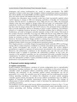
d
D
r
B
r
d
Cylindrical bore Tapered bore
taper 1:12
Da
da
ra
ra
B-81
Constant
Axial load factors Mass
kg
cylindrical bore tapered bore
eY
1
Y
2
Y
o
(approx.)
●Self-Aligning Ball Bearings
0.22 2.81 4.35 2.95 0.414 0.407
0.33 1.91 2.95 2.00 0.493 0.482
0.25 2.57 3.98 2.69 0.709 0.698
0.43 1.45 2.25 1.52 0.918 0.895
0.21 2.99 4.63 3.13 0.457 0.448
0.30 2.07 3.20 2.17 0.54 0.528
0.25 2.56 3.95 2.68 0.953 0.938
0.41 1.53 2.36 1.60 1.23 1.2
0.21 3.07 4.75 3.21 0.515 0.504
0.28 2.23 3.45 2.33 0.583 0.569
0.23 2.7 4.19 2.83 1.2 1.18
0.42 1.49 2.3 1.56 1.63 1.59
0.20 3.19 4.94 3.34 0.692 0.679
0.28 2.24 3.47 2.35 0.787 0.769
0.23 2.71 4.20 2.84 1.58 1.56
0.41 1.53 2.37 1.6 2.1 2.05
0.18 3.41 5.27 3.57 0.879 0.864
0.28 2.26 3.5 2.37 1.08 1.06
0.22 2.85 4.42 2.99 1.96 1.93
0.40 1.56 2.41 1.63 2.59 2.52
0.17 3.70 5.73 3.88 1.13 1.11
0.28 2.26 3.5 2.37 1.44 1.41
0.23 2.74 4.25 2.87 2.42 2.38
0.38 1.64 2.54 1.72 3.2 3.12
0.18 3.48 5.38 3.64 1.24
―
0.26 2.38 3.68 2.49 1.52
―
0.22 2.83 4.37 2.96 2.99
―
0.38 1.67 2.59 1.75 3.92
―
0.17 3.61 5.58 3.78 1.33 1.31
0.25 2.52 3.89 2.63 1.58 1.54
0.22 2.81 4.35 2.95 3.55 3.5
0.38 1.65 2.55 1.72 4.78 4.66
Fa
Fr
XY X
Y
≦e
F
a
Fr
>e
P
r=XFr+YFa
Por=Fr+Yo Fa
For values of e,Y1,Y2 and Yo
see the table below.
1 Y1 0.65 Y2
Equivalent bearing load
dynamic
static
1 Smallest allowable dimension for chamfer dimension r. 2 "K" indicates bearings have tapered bore with a taper ratio of 1: 12.
B-82
●Self-Aligning Ball Bearings
Boundary dimensions Basic load ratings Limiting speeds Bearing numbers Abutment and
dynamic static dynamic static
fillet dimensions
mm kN kgf rpm mm
cylindrical tapered
2
d
a
D
a
r
as
dD Br
s min
1
C
r
C
or
C
r
C
or
grease oil
bore bore
min max max
80
85
90
95
100
105
110
d 80∼110mm
140 26 2 40.0 17.0 4,050 1,730 3,700 4,300
1216 1216K
89 131 2
140 33 2 48.5 19.9 4,950 2,030 3,400 4,000
2216 2216K
89 131 2
170 39 2.1 88.5 33.0 9,000 3,400 3,100 3,600
1316 1316K
91 159 2
170 58 2.1 128 45.0 13,100 4,600 2,900 3,400
2316 2316K
91 159 2
150 28 2 49.0 20.8 5,000 2,120 3,500 4,100
1217 1217K
94 141 2
150 36 2 58.0 23.6 5,950 2,400 3,200 3,800
2217 2217K
94 141 2
180 41 3 97.5 38.0 9,950 3,850 2,900 3,400
1317 1317K
98 167 2.5
180 60 3 140 51.5 14,300 5,250 2,700 3,200
2317 2317K
98 167 2.5
160 30 2 57.0 23.5 5,800 2,390 3,300 3,800
1218 1218K
99 151 2
160 40 2 70.0 28.7 7,150 2,930 3,100 3,600
2218 2218K
99 151 2
190 43 3 116 44.5 11,900 4,550 2,700 3,200
1318 1318K
103 177 2.5
190 64 3 152 57.5 15,500 5,850 2,600 3,000
2318 2318K
103 177 2.5
170 32 2.1 64.0 27.1 6,500 2,770 3,100 3,600
1219 1219K
106 159 2
170 43 2.1 83.5 34.5 8,500 3,500 2,900 3,400
2219 2219K
106 159 2
200 45 3 132 51.0 13,400 5,200 2,600 3,000
1319 1319K
108 187 2.5
200 67 3 165 64.5 16,800 6,550 2,400 2,800
2319 2319K
108 187 2.5
180 34 2.1 69.0 29.7 7,050 3,050 2,900 3,400
1220 1220K
111 169 2
180 46 2.1 94.0 38.5 9,600 3,900 2,700 3,200
2220 2220K
111 169 2
215 47 3 143 57.5 14,600 5,850 2,400 2,900
1320 1320K
113 202 2.5
215 73 3 192 79.0 19,600 8,100 2,300 2,700
2320 2320K
113 202 2.5
190 36 2.1 74.5 32.5 7,600 3,300 2,800 3,300
1221
―
116 179 2
190 50 2.1 109 45.0 11,100 4,550 2,600 3,100
2221
―
116 179 2
225 49 3 156 64.5 15,900 6,600 2,300 2,700
1321
―
118 212 2.5
225 77 3 205 87.0 20,900 8,850 2,200 2,600
2321
―
118 212 2.5
200 38 2.1 80.5 35.5 8,200 3,600 2,600 3,100
1222 1222K
121 189 2
200 53 2.1 124 51.5 12,700 5,250 2,500 2,900
2222 2222K
121 189 2
240 50 3 164 71.5 16,700 7,300 2,200 2,600
1322 1322K
123 227 2.5
240 80 3 217 94.5 22,100 9,650 2,100 2,400
2322 2322K
123 227 2.5
d
D
r
B
r
d
Cylindrical bore Tapered bore
taper 1:12
Da
da
ra
ra
B-83
Constant
Axial load factors Mass
kg
cylindrical bore tapered bore
eY
1
Y
2
Y
o
(approx.)
●Self-Aligning Ball Bearings
0.16 3.9 6.04 4.09 1.65 1.62
0.25 2.52 3.9 2.64 1.99 1.95
0.22 2.92 4.52 3.06 4.17 4.11
0.39 1.63 2.52 1.71 5.65 5.51
0.17 3.67 5.68 3.85 2.06 2.03
0.25 2.49 3.86 2.61 2.54 2.49
0.21 2.94 4.55 3.08 4.96 4.89
0.37 1.71 2.64 1.79 6.55 6.39
0.17 3.76 5.82 3.94 2.51 2.47
0.27 2.35 3.64 2.47 3.19 3.12
0.22 2.8 4.34 2.94 5.78 5.69
0.38 1.67 2.58 1.75 7.75 7.56
0.17 3.74 5.79 3.92 3.1 3.05
0.27 2.36 3.65 2.47 3.89 3.8
0.23 2.76 4.27 2.89 6.69 6.59
0.38 1.67 2.59 1.75 9.05 8.83
0.17 3.64 5.64 3.82 3.7 3.64
0.27 2.35 3.64 2.46 4.65 4.54
0.24 2.65 4.11 2.78 8.3 8.19
0.37 1.69 2.61 1.77 11.5 11.2
0.18 3.56 5.52 3.73 4.34
―
0.28 2.25 3.49 2.36 6.07
―
0.23 2.73 4.22 2.86 10
―
0.38 1.67 2.58 1.75 13.2
―
0.18 3.44 5.33 3.61 5.15 5.07
0.28 2.24 3.47 2.35 7.1 6.94
0.22 2.85 4.4 2.98 11.8 11.7
0.37 1.71 2.65 1.79 15.8 15.4
Fa
Fr
XY X
Y
≦e
F
a
Fr
>e
P
r=XFr+YFa
Por=Fr+Yo Fa
For values of e,Y1,Y2 and Yo
see the table below.
1 Y1 0.65 Y2
Equivalent bearing load
dynamic
static
Boundary dimensions Bearing numbers Abutment and fillet dimensions Mass
1
mm mm kg
d
a
d
b
S
1
D
a
r
as
d
1
B
1
d
2
B
2
min max min max max (approx.)
●Adapters
B-84
1 Refers to adapter mass.
Note: 1. For bearing dimensions, basic rated loads, allowable rotations, and mass, refer to pages B-80 to B-82.
2. Adapters for series 12 bearings can also be used with H2 and H3 series bearings.
Caution: the B1 dimension of H3 series bearings is longer than that of H2 series bearings.
3. Adapter numbers which are appended with the code "X" indicate narrow slit type adapters which use washer with straight inner tabs.
4. For adapter locknut and washer dimensions, please refer to pages D-2 to D-7, and D-12 to D-14.
d 17∼50mm
(for self-aligning ball bearings)
17
20
25
30
35
40
45
50
d1 d2
B2
B1
Da
S1
db da
ra
24 32 7 1204K;H 204 23 27 5 41 1 0.041
28 32 7 2204K;H 304 24 28 5 41 1 0.045
28 32 7 1304K;H 304 24 31 8 45 1 0.045
31 32 7 2304K;H2304 24 28 5 45 1 0.049
26 38 8 1205K;H 205X 28 33 5 46 1 0.07
29 38 8 2205K;H 305X 29 33 5 46 1 0.075
29 38 8 1305K;H 305X 29 37 6 55 1 0.075
35 38 8 2305K;H2305X 29 34 5 55 1 0.087
27 45 8 1206K;H206X 33 39 5 56 1 0.099
31 45 8 2206K;H 306X 34 39 5 56 1 0.109
31 45 8 1306K;H 306X 34 44 6 65 1 0.109
38 45 8 2306K;H2306X 35 40 5 65 1 0.126
29 52 9 1207K;H 207X 38 46 5 65 1 0.125
35 52 9 2207K;H 307X 39 45 5 65 1 0.142
35 52 9 1307K;H 307X 39 50 7 71.5 1.5 0.142
43 52 9 2307K;H2307X 40 46 5 71.5 1.5 0.165
31 58 10 1208K;H 208X 44 52 5 73 1 0.174
36 58 10 2208K;H 308X 44 50 5 73 1 0.189
36 58 10 1308K;H 308X 44 56 5 81.5 1.5 0.189
46 58 10 2308K;H2308X 45 52 5 81.5 1.5 0.224
33 65 11 1209K;H 209X 49 57 5 78 1 0.227
39 65 11 2209K;H 309X 49 57 8 78 1 0.248
39 65 11 1309K;H 309X 49 61 5 91.5 1.5 0.248
50 65 11 2309K;H2309X 50 58 5 91.5 1.5 0.28
35 70 12 1210K;H 210X 53 62 5 83 1 0.274
42 70 12 2210K;H 310X 54 63 10 83 1 0.303
42 70 12 1310K;H 310X 54 67 5 100 2 0.303
55 70 12 2310K;H2310X 56 65 5 100 2 0.362
37 75 12 1211K;H 211X 60 70 6 91.5 1.5 0.308
●Adapters
Boundary dimensions Bearing numbers Abutment and fillet dimensions Mass
1
mm mm kg
d
a
d
b
S
1
D
a
r
as
d
1
B
1
d
2
B
2
min max min max max (approx.)
B-85
d 50∼85mm
(for self-aligning ball bearings)
1 Refers to adapter mass.
Note: 1. For bearing dimensions, basic rated loads, allowable rotations, and mass, refer to pages B-80 to B-82.
2. Adapters for series 12 bearings can also be used with H2 and H3 series bearings.
Caution: the B1 dimension of H3 series bearings is longer than that of H2 series bearings.
3. Adapter numbers which are appended with the code "X" indicate narrow slit type adapters which use washer with straight inner tabs.
4. For adapter locknut and washer dimensions, please refer to pages D-2 to D-7, and D-12 to D-14.
d1 d2
B2
B1
Da
S1
db da
ra
45 75 12 2211K;H 311X 60 69 11 91.5 1.5 0.345
45 75 12 1311K;H 311X 60 73 6 110 2 0.345
59 75 12 2311K;H2311X 61 71 6 110 2 0.42
38 80 13 1212K;H 212X 64 76 5 101.5 1.5 0.346
47 80 13 2212K;H 312X 65 75 9 101.5 1.5 0.394
47 80 13 1312K;H 312X 65 79 5 118 2 0.394
62 80 13 2312K;H2312X 66 77 5 118 2 0.481
40 85 14 1213K;H 213X 70 83 5 111.5 1.5 0.401
50 85 14 2213K;H 313X 70 81 8 111.5 1.5 0.458
50 85 14 1313K;H 313X 70 85 5 128 2 0.458
65 85 14 2313K;H2313X 72 84 5 128 2 0.557
43 98 15 1215K;H 215X 80 93 5 121.5 1.5 0.707
55 98 15 2215K;H 315X 80 93 12 121.5 1.5 0.831
55 98 15 1315K;H 315X 80 97 5 148 2 0.831
73 98 15 2315K;H2315X 82 96 5 148 2 1.05
46 105 17 1216K;H 216X 85 100 5 130 2 0.882
59 105 17 2216K;H 316X 86 98 12 130 2 1.03
59 105 17 1316K;H 316X 86 103 5 158 2 1.03
78 105 17 2316K;H2316X 87 103 5 158 2 1.28
50 110 18 1217K;H 217X 90 106 6 140 2 1.02
63 110 18 2217K;H 317X 91 104 12 140 2 1.18
63 110 18 1317K;H 317X 91 110 6 166 2.5 1.18
82 110 18 2317K;H2317X 94 110 6 166 2.5 1.45
52 120 18 1218K;H 218X 95 111 6 150 2 1.19
65 120 18 2218K;H 318X 96 112 10 150 2 1.37
65 120 18 1318K;H 318X 96 116 6 176 2.5 1.37
86 120 18 2318K;H2318X 99 117 6 176 2.5 1.69
55 125 19 1219K;H 219X 101 118 7 158 2 1.37
68 125 19 2219K;H 319X 102 117 9 158 2 1.56
50
55
60
65
70
75
80
85
●Adapters
(for self-aligning ball bearings)
Boundary dimensions Bearing numbers Abutment and fillet dimensions Mass
1
mm mm kg
d
a
d
b
S
1
D
a
r
as
d
1
B
1
d
2
B
2
min max min max max (approx.)
B-86
d 85∼100mm
1 Refers to adapter mass.
Note: 1. For bearing dimensions, basic rated loads, allowable rotations, and mass, refer to pages B-80 to B-82.
2. Adapters for series 12 bearings can also be used with H2 and H3 series bearings.
Caution: the B1 dimension of H3 series bearings is longer than that of H2 series bearings.
3. Adapter numbers which are appended with the code "X" indicate narrow slit type adapters which use washer with straight inner tabs.
4. For adapter locknut and washer dimensions, please refer to pages D-2 to D-7, and D-12 to D-14.
68 125 19 1319K;H 319X 102 123 7 186 2.5 1.56
90 125 19 2319K;H2319X 105 123 7 186 2.5 1.92
58 130 20 1220K;H 220X 106 125 7 168 2 1.49
71 130 20 2220K;H 320X 107 123 8 168 2 1.69
71 130 20 1320K;H 320X 107 130 7 201 2.5 1.69
97 130 20 2320K;H2320X 110 129 7 201 2.5 2.15
63 145 21 1222K;H 222X 116 138 7 188 2 1.93
77 145 21 2222K;H 322X 117 137 6 188 2 2.18
77 145 21 1322K;H 322X 117 150 9 226 2.5 2.18
105 145 21 2322K;H2322X 121 142 7 226 2.5 2.74
90
85
100
d1 d2
B2
B1
Da
S1
db da
ra
●Adapters
B-87
1. Types, design features, and
characteristics
Since the rolling elements in cylindrical roller bearings
make line contact with raceways, these bearings can
accommodate heavy radial loads. The rollers are guided by
ribs on either the inner or outer ring, therefore these bearings
are also suitable for high speed applications. Furthermore,
cylindrical roller bearings are separable, and relatively easy
to install and disassemble even when interference fits are
required.
Among the various types of cylindrical roller bearings,
Type E has a high load capacity and its boundary
B-89
dimensions are identical to standard type. HT type has a
large axial load capacity, and HL type provides extended
wear life in conditions where the development of a lubricating
film inside the bearing is difficult.
Double and multiple row bearing arrangements are also
available.
For extremely heavy load applications, the non-separable
full complement SL type bearing offers special advantages.
Table 1 shows the various types and characteristics of
single row cylindrical roller bearings. Table 2 shows the
characteristics of non-standard type cylindrical roller
bearings.
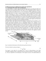
Type code Design Characteristics
¡NU type outer rings have double ribs; outer ring and roller as well as cage can be separated
from inner ring. N type inner ring have double ribs; inner ring and roller as well as cage can
be separated from outer ring.
¡Unable to accommodate even the slightest axial loads.
¡This type is extremely suitable for, and widely used as, the floating side bearing.
¡NJ type has double ribs on outer ring, single rib on inner ring; NF type has single rib on outer
ring, and double rib on inner ring.
¡Can receive single direction axial loads.
¡When there is no distinction between the fixed side and floating side bearing, can be used as
a pair in close proximity.
¡NUP type has a collar ring attached to the ribless side of the inner ring; NH type is NJ type
with an L type collar ring attached. All of these collar rings are separable, and therefore it is
necessary to fix the inner ring axially.
¡Can accommodate axial loads in either direction.
¡Widely used as the shaft's fixed-side bearing.
NU type
N type
NJ type
NF type
NUP type
NH type
(NJ + HJ)
NUP type
NF type
NJ type
N type
NU type
NH type
Table 1 Cylindrical roller bearing types and characteristics
Cylindrical roller bearing E Type cylindrical roller bearing Double row cylindrical roller bearing Four row cylindrical roller bearing
●Cylindrical Roller Bearings
B-90
Bearing type Characteristics
E Type cylindrical
roller bearing
¡Boundary dimensions identical to standard type; load capacity can be increased by increasing roller
diameter, roller length, or roller number.
¡Identified by addition of "E" to end of basic roller number.
¡Enables compact design due to its high load rating.
¡Rollers' inscribed circle diameter differs from standard type rollers and therefore cannot be interchanged.
Large axial load use
cylindrical roller bearings
(HT type)
Double row cylindrical
roller bearings
¡Can accommodate larger axial loads than standard type thanks to improved geometry of the rib roller
end surface.
¡Please consult NTN Engineering concerning the many factors which require consideration, such as
load, lubricant, and installation conditions.
Four row cylindrical
roller bearings
SL type cylindrical
roller bearings
¡NN type and NNU type available.
¡Widely used for applications requiring thin-walled bearings, such the main shafts of machine tools,
rolling machine rollers, and in printing equipment.
¡Used mainly in the necks of rolling machine rollers; designed for maximum rated load to accommodate
the severely limited space in the roller neck section of such equipment.
¡Many varieties exist, including sealed types, which have been specially designed for high speed use, to
prevent creeping, provide dust and water proofing properties, etc. Contact NTN Engineering.
¡Full complement roller bearing capable of handling heavy loads.
¡Consult NTN Engineering regarding special application designs for SL type cylindrical roller bearings.
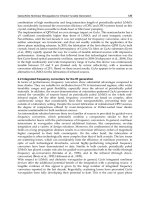
Remarks: In the dimension tables, both E type and standard type are listed, but in the future JIS will change to E type.
180mm 100mm 215mm 120mm
E type Standard type
NU2220E
Cr=335kN
E type bearing
NU320
C
r=315kN
Standard type
bearing
NU224E
C
r=335kN
E type bearing
Table 2 Non-standard type cylindrical roller bearing characteristics
●Cylindrical Roller Bearings
B-91
2. Standard cage types
Table 3 shows the standard varieties for cylindrical roller
bearings.
The basic rated loads listed in the dimension charts
correspond to values achieved with the standard cages listed
in Table 3. Furthermore, please note that even for the
identical bearing, in cases where the number of rolling
elements or the cage type differs, the basic rated load will
also differ from the values listed in the dimension charts.
Table 3 Standard cage types
Bearing
series
Molded resin
cage
Pressed cage Machined cage
NU10
NU 2
NU2E
NU22
NU22E
NU3
NU3E
NU23
NU23E
NU4
― 1005∼10/500
208∼230 232∼264
219E∼240E204E∼218E
2204E∼2218E
304E∼314E
2304E∼2311E
2208∼2230
308∼324
2308∼2320
2232∼2264
2219E∼2240E
326∼356
315E∼332E
2322∼2356
2312E∼2332E
405∼416
Note: 1) Within the same bearing series, cage type is identical even
if the type code (NJ, NUP, N, NF) differs.
2) For high speed and other special applications, machined
cages can be manufactured when necessary.
Consult
NTN
Engineering.
3) Among E type bearings (those using molded resin
cages), certain varieties may also use pressed cages.
Consult
NTN
Engineering.
4) Although machined cages are standard for two row and four
row cylindrical roller bearings, molded resin cages may also
be used in some of these bearings for machine tool
applications.
5) Due to their material properties, molded resin cages
cannot be used in applications where temperatures
exceed 120℃.
―
――
―
―
―
―
―
―
―
―
3. Allowable misalignment
Although values vary somewhat depending on bearing
type and internal specifications, under general load
conditions, to avoid the occurrence of edge loading,
allowable misalignments have been set as follows:
Bearing width series 0 or 1:………………0.001 rad (3.5')
Bearing width series 2:……………………0.0005 rad (1.5')
Double row cylindrical roller bearings
1
:
……0.0005 rad (1.5')
1 Does not include high precision bearings for machine tool
main shaft applications.
Boundary dimensions Basic load ratings Limiting speeds
1
Bearing numbers
dynamic static dynamic static
mm kN kgf rpm
type type type type
dD Br
s min
2
r
1s min
2
C
r
C
or
C
r
C
or
grease oil NU NJ NUP N
●Cylindrical Roller Bearings
B-92
1 This value achieved with machined cages; when pressed cages are used, 80% of this value is acceptable.
2 Minimal allowable dimension for chamfer dimension r or r
1.
d 20∼35mm
r
r
1
D
FW
B
d
B
D
d J
r
1
r
J
r
1
r
r
J
r
1
r1
EW
r
Type NU Type NJ Type NUP Type N Type NF
20
25
30
35
40
47 14 1 0.6 25.7 22.6 2,620 2,310 15,000 18,000 NU204E NJ NUP N
47 18 1 0.6 30.5 28.3 3,100 2,890 14,000 16,000 NU2204E NJ NUP N
52 15 1.1 0.6 31.5 26.9 3,200 2,740 13,000 15,000 NU304E NJ NUP N
52 21 1.1 0.6 42.0 39.0 4,300 3,950 12,000 14,000 NU2304E NJ NUP N
47 12 0.6 0.3 15.1 14.1 1,540 1,430 16,000 19,000 NU1005 NJ NUP N
52 15 1 0.6 29.3 27.7 2,990 2,830 13,000 15,000 NU205E NJ NUP N
52 18 1 0.6 35.0 34.5 3,550 3,550 11,000 13,000 NU2205E NJ NUP N
62 17 1.1 1.1 41.5 37.5 4,250 3,800 11,000 13,000 NU305E NJ NUP N
62 24 1.1 1.1 57.0 56.0 5,800 5,700 9,700 11,000 NU2305E NJ NUP N
80 21 1.5 1.5 46.5 40.0 4,750 4,050 8,500 10,000 NU405 NJ NUP N
55 13 1 0.6 19.7 19.6 2,000 2,000 14,000 16,000 NU1006 NJ NUP N
62 16 1 0.6 39.0 37.5 4,000 3,800 11,000 13,000 NU206E NJ NUP N
62 20 1 0.6 49.0 50.0 5,000 5,100 9,700 11,000 NU2206E NJ NUP N
72 19 1.1 1.1 53.0 50.0 5,400 5,100 9,300 11,000 NU306E NJ NUP N
72 27 1.1 1.1 74.5 77.5 7,600 7,900 8,300 9,700 NU2306E NJ NUP N
90 23 1.5 1.5 62.5 55.0 6,400 5,600 7,300 8,500 NU406 NJ NUP N
62 14 1 0.6 22.6 23.2 2,310 2,360 12,000 15,000 NU1007 NJ NUP N
72 17 1.1 0.6 50.5 50.0 5,150 5,100 9,500 11,000 NU207E NJ NUP N
72 23 1.1 0.6 61.5 65.5 6,300 6,650 8,500 10,000 NU2207E NJ NUP N
80 21 1.5 1.1 71.0 71.0 7,200 7,200 8,100 9,600 NU307E NJ NUP N
80 31 1.5 1.1 99.0 109 10,100 11,100 7,200 8,500 NU2307E NJ NUP N
100 25 1.5 1.5 75.5 69.0 7,700 7,050 6,400 7,500 NU407 NJ NUP N
68 15 1 0.6 27.3 29.0 2,780 2,950 11,000 13,000 NU1008 NJ NUP N
80 18 1.1 1.1 43.5 43.0 4,450 4,350 9,400 11,000 NU208 NJ NUP N
80 18 1.1 1.1 55.5 55.5 5,700 5,650 8,500 10,000 NU208E NJ NUP
―
80 23 1.1 1.1 58.0 62.0 5,950 6,300 8,500 10,000 NU2208 NJ NUP N
80 23 1.1 1.1 72.5 77.5 7,400 7,900 7,600 8,900 NU2208E NJ NUP
―
90 23 1.5 1.5 58.5 57.0 6,000 5,800 8,000 9,400 NU308 NJ NUP N
90 23 1.5 1.5 83.0 81.5 8,500 8,300 7,200 8,500 NU308E NJ NUP
―
90 33 1.5 1.5 82.5 88.0 8,400 8,950 7,000 8,200 NU2308 NJ NUP N
90 33 1.5 1.5 114 122 11,600 12,500 6,400 7,500 NU2308E NJ NUP
―
110 27 2 2 95.5 89.0 9,750 9,100 5,700 6,700 NU408 NJ NUP N
●Cylindrical Roller Bearings
Dimensions Abutment and fillet dimensions Mass
mm mm kg
type d
a
d
b
d
c
d
d
d
e
D
a
D
b
r
as
r
1as
type NU type N
NF F
w
E
w
J
min min max min min max max min
4
max max (approx.)
B-93
4 Does not apply to side of the outer ring rib of type NF bearings.
―
26.5
―
29.5 24
―
26 29 32 42
――
1 0.6 0.122
―
―
26.5
―
29.5 24
―
26 29 32 42
――
1 0.6 0.158
―
―
27.5
―
31.1 24
―
27 30 33 45.5
――
1 0.6 0.176
―
―
27.5
―
31.1 24
―
27 30 33 45.5
――
1 0.6 0.242
―
―
30.5 41.5 32.7 27 29 30 32 33 43 45 42.5 0.6 0.3 0.092 0.091
―
31.5
―
34.5 29
―
31 34 37 47
――
1 0.6 0.151
―
―
31.5
―
34.5 29
―
31 34 37 47
――
1 0.6 0.186
―
―
34
―
38 31.5
―
33 37 40 55.5
――
1 1 0.275
―
―
34
―
38 31.5
―
33 37 40 55.5
――
1 1 0.386
―
NF 38.8 62.8 43.6 33 33 38 41 46 72 72 64 1.5 1.5 0.55 0.536
―
36.5 48.5 38.9 34 35 35 38 39.5 50 51 49.5 1 0.6 0.13 0.128
―
37.5
―
41.1 34
―
37 40 44 57
――
1 0.6 0.226
―
―
37.5
―
41.1 34
―
37 40 44 57
――
1 0.6 0.297
―
―
40.5
―
44.9 36.5
―
40 44 48 65.5
――
1 1 0.398
―
―
40.5
―
44.9 36.5
―
40 44 48 65.5
――
1 1 0.58
―
NF 45 73 50.5 38 38 44 47 52 82 82 74 1.5 1.5 0.751 0.732
―
42 55 44.6 39 40 41 44 45 57 58 56 1 0.6 0.179 0.176
―
44
―
48 39
―
43 46 50 65.5
――
1 0.6 0.327
―
―
44
―
48 39
―
43 46 50 65.5
――
1 0.6 0.455
―
―
46.2
―
51 41.5
―
45 48 53 72
――
1.5 1 0.545
―
―
46.2
―
51 41.5
―
45 48 53 72
――
1.5 1 0.78
―
NF 53 83 59 43 43 52 55 61 92 92 84 1.5 1.5 0.99 0.965
―
47 61 49.8 44 45 46 49 50.5 63 64 62 1 0.6 0.22 0.217
NF 50 70 54.2 46.5 46.5 49 52 56 73.5 73.5 72 1 1 0.378 0.37
―
49.5
―
53.9 46.5
―
49 52 56 73.5
――
1 1 0.426
―
―
50 70 54.2 46.5 46.5 49 52 56 73.5 73.5 72 1 1 0.49 0.48
―
49.5
―
53.9 46.5
―
49 52 56 73.5
――
1 1 0.552
―
NF 53.5 77.5 58.4 48 48 51 55 60 82 82 80 1.5 1.5 0.658 0.643
―
52
―
57.6 48
―
51 55 60 82
――
1.5 1.5 0.754
―
―
53.5 77.5 58.4 48 48 51 55 60 82 82 80 1.5 1.5 0.951 0.932
―
52
―
57.6 48
―
51 55 60 82
――
1.5 1.5 1.06
―
NF 58 92 64.8 49 49 57 60 67 101 101 93 2 2 1.3 1.27
dd dc
da
r
a
r1a
dc Da
de db
ra
Db
Db
Pr=Fr
Por=Fr
r1a
Equivalent bearing load
dynamic
static
●Cylindrical Roller Bearings
Boundary dimensions Basic load ratings Limiting speeds
1
Bearing numbers
dynamic static dynamic static
mm kN kgf rpm
type type type type
dD Br
s min
2
r
1s min
2
C
r
C
or
C
r
C
or
grease oil NU NJ NUP N
B-94
1 This value achieved with machined cages; when pressed cages are used, 80% of this value is acceptable.
2 Minimal allowable dimension for chamfer dimension r or r
1.
d 35∼55mm
75 16 1 0.6 31.0 34.0 3,200 3,450 9,900 12,000 NU1009 NJ NUP N
85 19 1.1 1.1 46.0 47.0 4,700 4,800 8,400 9,900 NU209 NJ NUP N
85 19 1.1 1.1 63.0 66.5 6,450 6,800 7,600 9,000 NU209E NJ NUP
―
85 23 1.1 1.1 61.5 68.0 6,250 6,900 7,600 9,000 NU2209 NJ NUP N
85 23 1.1 1.1 76.0 84.5 7,750 8,600 6,800 8,000 NU2209E NJ NUP
―
100 25 1.5 1.5 74.0 71.0 7,550 7,250 7,200 8,400 NU309 NJ NUP N
100 25 1.5 1.5 97.5 98.5 9,950 10,000 6,500 7,600 NU309E NJ NUP
―
100 36 1.5 1.5 99.0 104 10,100 10,600 6,300 7,400 NU2309 NJ NUP N
100 36 1.5 1.5 137 153 14,000 15,600 5,700 6,800 NU2309E NJ NUP
―
120 29 2 2 107 102 10,900 10,400 5,100 6,000 NU409 NJ NUP N
80 16 1 0.6 32.0 36.0 3,300 3,700 8,900 11,000 NU1010 NJ NUP N
90 20 1.1 1.1 48.0 51.0 4,900 5,200 7,600 9,000 NU210 NJ NUP N
90 20 1.1 1.1 66.0 72.0 6,750 7,350 6,900 8,100 NU210E NJ NUP
―
90 23 1.1 1.1 64.0 73.5 6,550 7,500 6,900 8,100 NU2210 NJ NUP N
90 23 1.1 1.1 79.5 91.5 8,100 9,350 6,200 7,300 NU2210E NJ NUP
―
110 27 2 2 87.0 86.0 8,850 8,800 6,500 7,700 NU310 NJ NUP N
110 27 2 2 110 113 11,200 11,500 5,900 6,900 NU310E NJ NUP
―
110 40 2 2 121 131 12,300 13,400 5,700 6,700 NU2310 NJ NUP N
110 40 2 2 163 187 16,600 19,000 5,200 6,100 NU2310E NJ NUP
―
130 31 2.1 2.1 129 124 13,200 12,600 4,700 5,500 NU410 NJ NUP N
90 18 1.1 1 37.5 44.0 3,850 4,450 8,200 9,700 NU1011 NJ NUP N
100 21 1.5 1.1 58.0 62.5 5,900 6,350 6,900 8,200 NU211 NJ NUP N
100 21 1.5 1.1 82.5 93.0 8,400 9,500 6,300 7,400 NU211E NJ NUP
―
100 25 1.5 1.1 75.5 87.0 7,700 8,900 6,300 7,400 NU2211 NJ NUP N
100 25 1.5 1.1 97.0 114 9,900 11,700 5,600 6,600 NU2211E NJ NUP
―
120 29 2 2 111 111 11,300 11,400 5,900 7,000 NU311 NJ NUP N
120 29 2 2 137 143 14,000 14,600 5,300 6,300 NU311E NJ NUP
―
120 43 2 2 148 162 15,100 16,500 5,200 6,100 NU2311 NJ NUP N
120 43 2 2 201 233 20,500 23,800 4,700 5,600 NU2311E NJ NUP
―
140 33 2.1 2.1 139 138 14,200 14,100 4,300 5,000 NU411 NJ NUP N
95 18 1.1 1 40.0 48.5 4,100 4,950 7,500 8,800 NU1012 NJ NUP N
110 22 1.5 1.5 68.5 75.0 7,000 7,650 6,400 7,600 NU212 NJ NUP N
110 22 1.5 1.5 97.5 107 9,950 10,900 5,800 6,800 NU212E NJ NUP
―
110 28 1.5 1.5 96.0 116 9,800 11,800 5,800 6,800 NU2212 NJ NUP N
r
r
1
D
FW
B
d
B
D
d J
r
1
r
J
r
1
r
r
J
r
1
r1
EW
r
Type NU Type NJ Type NUP Type N Type NF
45
50
55
60
●Cylindrical Roller Bearings
Dimensions Abutment and fillet dimensions Mass
mm mm kg
type d
a
d
b
d
c
d
d
d
e
D
a
D
b
r
as
r
1as
type NU type N
NF F
w
E
w
J
min min max min min max max min
4
max max (approx.)
B-95
4 Does not apply to side of the outer ring rib of type NF bearings.
―
52.5 67.5 55.5 49 50 52 54 56 70 71 68.5 1 0.6 0.28 0.276
NF 55 75 59 51.5 51.5 54 57 61 78.5 78.5 77 1 1 0.432 0.423
―
54.5
―
58.9 51.5
―
54 57 61 78.5
――
1 1 0.495
―
―
55 75 59 51.5 51.5 54 57 61 78.5 78.5 77 1 1 0.53 0.52
―
54.5
―
58.9 51.5
―
54 57 61 78.5
――
1 1 0.6
―
NF 58.5 86.5 64 53 53 57 60 66 92 92 89 1.5 1.5 0.877 0.857
―
58.5
―
64.5 53
―
57 60 66 92
――
1.5 1.5 0.996
―
―
58.5 86.5 64 53 53 57 60 66 92 92 89 1.5 1.5 1.27 1.24
―
58.5
―
64.5 53
―
57 60 66 92
――
1.5 1.5 1.41
―
NF 64.5 100.5 71.8 54 54 63 66 74 111 111 102 2 2 1.62 1.58
―
57.5 72.5 60.5 54 55 57 59 61 75 76 73.5 1 0.6 0.295 0.291
NF 60.4 80.4 64.6 56.5 56.5 58 62 67 83.5 83.5 83 1 1 0.47 0.46
―
59.5
―
63.9 56.5
―
58 62 67 83.5
――
1 1 0.54
―
―
60.4 80.4 64.6 56.5 56.5 58 62 67 83.5 83.5 83 1 1 0.571 0.56
―
59.5
―
63.9 56.5
―
58 62 67 83.5
――
1 1 0.652
―
NF 65 95 71 59 59 63 67 73 101 101 98 2 2 1.14 1.11
―
65
―
71.4 59
―
63 67 73 101
――
2 2 1.3
―
―
65 95 71 59 59 63 67 73 101 101 98 2 2 1.7 1.67
―
65
―
71.4 59
―
63 67 73 101
――
2 2 1.9
―
NF 70.8 110.8 78.8 61 61 69 73 81 119 119 112 2 2 2.02 1.97
―
64.5 80.5 67.7 60 61.5 63 66 68.5 83.5 85 81.5 1 1 0.442 0.435
NF 66.5 88.5 70.8 61.5 63 65 68 73 92 93.5 91 1.5 1 0.638 0.626
―
66
―
70.8 61.5
―
65 68 73 92
――
1.5 1 0.718
―
―
66.5 88.5 70.8 61.5 63 65 68 73 92 93.5 91 1.5 1 0.773 0.758
―
66
―
70.8 61.5
―
65 68 73 92
――
1.5 1 0.968
―
NF 70.5 104.5 77.2 64 64 69 72 80 111 111 107 2 2 1.45 1.42
―
70.5
―
77.7 64
―
69 72 80 111
――
2 2 1.65
―
―
70.5 104.5 77.2 64 64 69 72 80 111 111 107 2 2 2.17 2.13
―
70.5
―
77.7 64
―
69 72 80 111
――
2 2 2.37
―
NF 77.2 117.2 85.2 66 66 76 79 87 129 129 119 2 2 2.48 2.42
―
69.5 85.5 72.7 65 66.5 68 71 73.5 88.5 90 86.5 1 1 0.474 0.467
NF 73.5 97.5 78.4 68 68 71 75 80 102 102 100 1.5 1.5 0.818 0.802
―
72
―
77.6 68
―
71 75 80 102
――
1.5 1.5 0.923
―
―
73.5 97.5 78.4 68 68 71 75 80 102 102 100 1.5 1.5 1.06 1.04
dd dc
da
r
a
r1a
dc Da
de db
ra
Db
Db
Pr=Fr
Por=Fr
r1a
Equivalent bearing load
dynamic
static
●Cylindrical Roller Bearings
Boundary dimensions Basic load ratings Limiting speeds
1
Bearing numbers
dynamic static dynamic static
mm kN kgf rpm
type type type type
dD Br
s min
2
r
1s min
2
C
r
C
or
C
r
C
or
grease oil NU NJ NUP N
B-96
1 This value achieved with machined cages; when pressed cages are used, 80% of this value is acceptable.
2 Minimal allowable dimension for chamfer dimension r or r
1.
d 55∼70mm
110 28 1.5 1.5 131 157 13,400 16,000 5,200 6,100 NU2212E NJ NUP
―
130 31 2.1 2.1 124 126 12,600 12,900 5,500 6,500 NU312 NJ NUP N
130 31 2.1 2.1 150 157 15,200 16,000 4,900 5,800 NU312E NJ NUP
―
130 46 2.1 2.1 169 188 17,200 19,200 4,800 5,700 NU2312 NJ NUP N
130 46 2.1 2.1 222 262 22,700 26,700 4,400 5,200 NU2312E NJ NUP
―
150 35 2.1 2.1 167 168 17,100 17,200 3,900 4,600 NU412 NJ NUP N
100 18 1.1 1 41.0 51.0 4,200 5,200 7,000 8,200 NU1013 NJ NUP N
120 23 1.5 1.5 84.0 94.5 8,550 9,650 5,900 7,000 NU213 NJ NUP N
120 23 1.5 1.5 108 119 11,000 12,100 5,400 6,300 NU213E NJ NUP
―
120 31 1.5 1.5 120 149 12,200 15,200 5,400 6,300 NU2213 NJ NUP N
120 31 1.5 1.5 149 181 15,200 18,400 4,800 5,600 NU2213E NJ NUP
―
140 33 2.1 2.1 135 139 13,800 14,200 5,100 6,000 NU313 NJ NUP N
140 33 2.1 2.1 181 191 18,400 19,500 4,600 5,400 NU313E NJ NUP
―
140 48 2.1 2.1 188 212 19,100 21,700 4,400 5,200 NU2313 NJ NUP N
140 48 2.1 2.1 248 287 25,200 29,300 4,100 4,800 NU2313E NJ NUP
―
160 37 2.1 2.1 182 186 18,600 19,000 3,600 4,300 NU413 NJ NUP N
110 20 1.1 1 58.5 70.5 5,950 7,200 6,500 7,600 NU1014 NJ NUP N
125 24 1.5 1.5 83.5 95.0 8,500 9,700 5,500 6,500 NU214 NJ NUP N
125 24 1.5 1.5 119 137 12,100 14,000 5,000 5,900 NU214E NJ NUP
―
125 31 1.5 1.5 119 151 12,200 15,400 5,000 5,900 NU2214 NJ NUP N
125 31 1.5 1.5 156 194 15,900 19,800 4,500 5,200 NU2214E NJ NUP
―
150 35 2.1 2.1 158 168 16,100 17,200 4,700 5,500 NU314 NJ NUP N
150 35 2.1 2.1 205 222 20,900 22,600 4,200 5,000 NU314E NJ NUP
―
150 51 2.1 2.1 223 262 22,700 26,700 4,100 4,800 NU2314 NJ NUP N
150 51 2.1 2.1 274 325 27,900 33,000 3,800 4,400 NU2314E NJ NUP
―
180 42 3 3 228 236 23,200 24,000 3,400 4,000 NU414 NJ NUP N
115 20 1.1 1 60.0 74.5 6,100 7,600 6,100 7,100 NU1015 NJ NUP N
130 25 1.5 1.5 96.5 111 9,850 11,300 5,100 6,000 NU215 NJ NUP N
130 25 1.5 1.5 130 156 13,300 16,000 4,700 5,500 NU215E NJ NUP
―
130 31 1.5 1.5 130 162 13,200 16,500 4,700 5,500 NU2215 NJ NUP N
130 31 1.5 1.5 162 207 16,500 21,100 4,200 4,900 NU2215E NJ NUP
―
160 37 2.1 2.1 190 205 19,400 20,900 4,400 5,200 NU315 NJ NUP N
160 37 2.1 2.1 240 263 24,500 26,800 4,000 4,700 NU315E NJ NUP
―
160 55 2.1 2.1 258 300 26,300 31,000 3,800 4,500 NU2315 NJ NUP N
r
r
1
D
FW
B
d
B
D
d J
r
1
r
J
r
1
r
r
J
r
1
r1
EW
r
Type NU Type NJ Type NUP Type N Type NF
60
65
70
75
●Cylindrical Roller Bearings
Dimensions Abutment and fillet dimensions Mass
mm mm kg
type d
a
d
b
d
c
d
d
d
e
D
a
D
b
r
as
r
1as
type NU type N
NF F
w
E
w
J
min min max min min max max min
4
max max (approx.)
B-97
4 Does not apply to side of the outer ring rib of type NF bearings.
―
72
―
77.6 68
―
71 75 80 102
――
1.5 1.5 1.21
―
NF 77 113 84.2 71 71 75 79 86 119 119 116 2 2 1.8 1.76
―
77
―
84.6 71
―
75 79 86 119
――
2 2 2.05
―
―
77 113 84.2 71 71 75 79 86 119 119 116 2 2 2.71 2.66
―
77
―
84.6 71
―
75 79 86 119
――
2 2 2.96
―
NF 83 127 91.8 71 71 82 85 94 139 139 128 2 2 3 2.93
―
74.5 90.5 77.7 70 71.5 73 76 78.5 93.5 95 91.5 1 1 0.485 0.477
NF 79.6 105.6 84.8 73 73 77 81 87 112 112 108 1.5 1.5 1.02 1
―
78.5
―
84.5 73
―
77 81 87 112
――
1.5 1.5 1.21
―
―
79.6 105.6 84.8 73 73 77 81 87 112 112 108 1.5 1.5 1.4 1.37
―
78.5
―
84.5 73
―
77 81 87 112
――
1.5 1.5 1.6
―
NF 83.5 121.5 91 76 76 81 85 93 129 129 125 2 2 2.23 2.18
―
82.5
―
91 76
―
81 85 93 129
――
2 2 2.54
―
―
83.5 121.5 91 76 76 81 85 93 129 129 125 2 2 3.27 3.2
―
82.5
―
91 76
―
81 85 93 129
――
2 2 3.48
―
NF 89.3 135.3 98.5 76 76 88 91 100 149 149 137 2 2 3.6 3.5
―
80 100 84 75 76.5 78 82 85 103.5 105 101 1 1 0.699 0.689
NF 84.5 110.5 89.6 78 78 82 86 92 117 117 114 1.5 1.5 1.12 1.1
―
83.5
―
89.5 78
―
82 86 92 117
――
1.5 1.5 1.3
―
―
84.5 110.5 89.6 78 78 82 86 92 117 117 114 1.5 1.5 1.47 1.44
―
83.5
―
89.5 78
―
82 86 92 117
――
1.5 1.5 1.7
―
NF 90 130 98 81 81 87 92 100 139 139 134 2 2 2.71 2.65
―
89
―
98 81
―
87 92 100 139
――
2 2 3.1
―
―
90 130 98 81 81 87 92 100 139 139 134 2 2 3.98 3.9
―
89
―
98 81
―
87 92 100 139
――
2 2 4.25
―
NF 100 152 110.5 83 83 99 102 112 167 167 153 2.5 2.5 5.24 5.1
―
85 105 89 80 81.5 83 87 90 108.5 110 106 1 1 0.738 0.727
NF 88.5 116.5 94 83 83 87 90 96 122 122 120 1.5 1.5 1.23 1.21
―
88.5
―
94.5 83
―
87 90 96 122
――
1.5 1.5 1.41
―
―
88.5 116.5 94 83 83 87 90 96 122 122 120 1.5 1.5 1.55 1.52
―
88.5
―
94.5 83
―
87 90 96 122
――
1.5 1.5 1.79
―
NF 95.5 139.5 104.2 86 86 93 97 106 149 149 143 2 2 3.28 3.21
―
95
―
104.6 86
―
93 97 106 149
――
2 2 3.74
―
―
95.5 139.5 104.2 86 86 93 97 106 149 149 143 2 2 4.87 4.77
dd dc
da
r
a
r1a
dc Da
de db
ra
Db
Db
Pr=Fr
Por=Fr
r1a
Equivalent bearing load
dynamic
static
●Cylindrical Roller Bearings
Boundary dimensions Basic load ratings Limiting speeds
1
Bearing numbers
dynamic static dynamic static
mm kN kgf rpm
type type type type
dD Br
s min
2
r
1s min
2
C
r
C
or
C
r
C
or
grease oil NU NJ NUP N
B-98
1 This value achieved with machined cages; when pressed cages are used, 80% of this value is acceptable.
2 Minimal allowable dimension for chamfer dimension r or r
1.
d 70∼90mm
160 55 2.1 2.1 330 395 33,500 40,000 3,500 4,100 NU2315E NJ NUP
―
190 45 3 3 262 274 26,800 27,900 3,200 3,700 NU415 NJ NUP N
125 22 1.1 1 72.5 90.5 7,400 9,250 5,700 6,700 NU1016 NJ NUP N
140 26 2 2 106 122 10,800 12,500 4,800 5,700 NU216 NJ NUP N
140 26 2 2 139 167 14,200 17,000 4,400 5,100 NU216E NJ NUP
―
140 33 2 2 147 186 15,000 19,000 4,400 5,100 NU2216 NJ NUP N
140 33 2 2 186 243 19,000 24,800 3,900 4,600 NU2216E NJ NUP
―
170 39 2.1 2.1 190 207 19,400 21,100 4,100 4,800 NU316 NJ NUP N
170 39 2.1 2.1 256 282 26,100 28,800 3,700 4,400 NU316E NJ NUP
―
170 58 2.1 2.1 274 330 27,900 34,000 3,600 4,200 NU2316 NJ NUP N
170 58 2.1 2.1 355 430 36,500 44,000 3,300 3,900 NU2316E NJ NUP
―
200 48 3 3 299 315 30,500 32,000 3,000 3,500 NU416 NJ NUP N
130 22 1.1 1 74.5 95.5 7,600 9,750 5,400 6,300 NU1017 NJ NUP N
150 28 2 2 120 140 12,300 14,300 4,500 5,300 NU217 NJ NUP N
150 28 2 2 167 199 17,000 20,300 4,100 4,800 NU217E NJ NUP
―
150 36 2 2 170 218 17,300 22,200 4,100 4,800 NU2217 NJ NUP N
150 36 2 2 217 279 22,200 28,400 3,700 4,300 NU2217E NJ NUP
―
180 41 3 3 212 228 21,600 23,300 3,900 4,600 NU317 NJ NUP N
180 41 3 3 291 330 29,700 33,500 3,500 4,100 NU317E NJ NUP
―
180 60 3 3 315 380 32,000 39,000 3,400 4,000 NU2317 NJ NUP N
180 60 3 3 395 485 40,000 49,500 3,100 3,700 NU2317E NJ NUP
―
140 24 1.5 1.1 88.0 114 9,000 11,700 5,100 5,900 NU1018 NJ NUP N
160 30 2 2 152 178 15,500 18,100 4,300 5,000 NU218 NJ NUP N
160 30 2 2 182 217 18,500 22,200 3,900 4,600 NU218E NJ NUP
―
160 40 2 2 197 248 20,100 25,300 3,900 4,600 NU2218 NJ NUP N
160 40 2 2 242 315 24,700 32,000 3,500 4,100 NU2218E NJ NUP
―
190 43 3 3 240 265 24,500 27,100 3,700 4,300 NU318 NJ NUP N
190 43 3 3 315 355 32,000 36,000 3,300 3,900 NU318E NJ NUP
―
190 64 3 3 325 395 33,500 40,000 3,200 3,800 NU2318 NJ NUP N
190 64 3 3 435 535 44,500 54,500 2,900 3,400 NU2318E NJ NUP
―
145 24 1.5 1.1 90.5 120 9,250 12,300 4,800 5,600 NU1019 NJ NUP N
170 32 2.1 2.1 166 195 16,900 19,900 4,000 4,700 NU219 NJ NUP N
170 32 2.1 2.1 220 265 22,500 27,000 3,600 4,300 NU219E NJ NUP
―
r
r
1
D
FW
B
d
B
D
d J
r
1
r
J
r
1
r
r
J
r
1
r1
EW
r
Type NU Type NJ Type NUP Type N Type NF
75
80
85
90
95
●Cylindrical Roller Bearings
Dimensions Abutment and fillet dimensions Mass
mm mm kg
type d
a
d
b
d
c
d
d
d
e
D
a
D
b
r
as
r
1as
type NU type N
NF F
w
E
w
J
min min max min min max max min
4
max max (approx.)
B-99
4 Does not apply to side of the outer ring rib of type NF bearings.
―
95
―
104.6 86
―
93 97 106 149
――
2 2 5.25
―
NF 104.5 160.5 116 88 88 103 107 118 177 177 162 2.5 2.5 6.22 6.06
―
91.5 113.5 95.9 85 86.5 90 94 97 118.5 120 114.5 1 1 0.98 0.965
NF 95.3 125.3 101.2 89 89 94 97 104 131 131 128 2 2 1.5 1.47
―
95.3
―
101.7 89
―
94 97 104 131
――
2 2 1.67
―
―
95.3 125.3 101.2 89 89 94 97 104 131 131 128 2 2 1.93 1.89
―
95.3
―
101.7 89
―
94 97 104 131
――
2 2 2.12
―
NF 103 147 111.8 91 91 99 105 114 159 159 151 2 2 3.86 3.77
―
101
―
111 91
―
99 105 114 159
――
2 2 4.22
―
―
103 147 111.8 91 91 99 105 114 159 159 151 2 2 5.79 5.67
―
101
―
111 91
―
99 105 114 159
――
2 2 6.25
―
NF 110 170 122 93 93 109 112 124 187 187 172 2.5 2.5 7.32 7.14
―
96.5 118.5 100.9 90 91.5 95 99 102 123.5 125 119.5 1 1 1.03 1.01
NF 101.8 133.8 108.2 94 94 99 104 110 141 141 137 2 2 1.87 1.83
―
100.5
―
107.7 94
―
99 104 110 141
――
2 2 2.11
―
―
101.8 133.8 108.2 94 94 99 104 110 141 141 137 2 2 2.44 2.39
―
100.5
―
107.7 94
―
99 104 110 141
――
2 2 2.68
―
NF 108 156 117.5 98 98 106 110 119 167 167 160 2.5 2.5 4.54 4.44
―
108
―
118.4 98
―
106 110 119 167
――
2.5 2.5 4.81
―
―
108 156 117.5 98 98 106 110 119 167 167 160 2.5 2.5 6.7 6.57
―
108
―
118.4 98
―
106 110 119 167
――
2.5 2.5 7.16
―
―
103 127 107.8 96.5 98 101 106 109 132 133.5 129 1.5 1 1.33 1.31
NF 107 143 114.2 99 99 105 109 116 151 151 146 2 2 2.3 2.25
―
107
―
114.6 99
―
105 109 116 151
――
2 2 2.44
―
―
107 143 114.2 99 99 105 109 116 151 151 146 2 2 3.1 3.04
―
107
―
114.6 99
―
105 109 116 151
――
2 2 3.33
―
NF 115 165 125 103 103 111 117 127 177 177 169 2.5 2.5 5.3 5.18
―
113.5
―
124.7 103
―
111 117 127 177
――
2.5 2.5 5.72
―
―
115 165 125 103 103 111 117 127 177 177 169 2.5 2.5 7.95 7.79
―
113.5
―
124.7 103
―
111 117 127 177
――
2.5 2.5 8.56
―
―
108 132 112.8 101.5 103 106 111 114 137 138.5 134 1.5 1 1.4 1.38
NF 113.5 151.5 121 106 106 111 116 123 159 159 155 2 2 2.78 2.72
―
112.5
―
121 106
―
111 116 123 159
――
2 2 3.02
―
dd dc
da
r
a
r1a
dc Da
de db
ra
Db
Db
Pr=Fr
Por=Fr
r1a
Equivalent bearing load
dynamic
static
●Cylindrical Roller Bearings
Boundary dimensions Basic load ratings Limiting speeds
1
Bearing numbers
dynamic static dynamic static
mm kN kgf rpm
type type type type
dD Br
s min
2
r
1s min
2
C
r
C
or
C
r
C
or
grease oil NU NJ NUP N
B-100
1 This value achieved with machined cages; when pressed cages are used, 80% of this value is acceptable.
2 Minimal allowable dimension for chamfer dimension r or r
1.
d 90∼110mm
170 43 2.1 2.1 230 298 23,500 30,500 3,600 4,300 NU2219 NJ NUP N
170 43 2.1 2.1 286 370 29,200 38,000 3,300 3,800 NU2219E NJ NUP
―
200 45 3 3 259 285 26,400 29,500 3,400 4,000 NU319 NJ NUP N
200 45 3 3 335 385 34,000 39,500 3,100 3,600 NU319E NJ NUP
―
200 67 3 3 370 460 38,000 47,000 3,000 3,500 NU2319 NJ NUP N
200 67 3 3 460 585 47,000 59,500 2,700 3,200 NU2319E NJ NUP
―
150 24 1.5 1.1 93.0 126 9,500 12,800 4,600 5,400 NU1020 NJ NUP N
180 34 2.1 2.1 183 217 18,600 22,200 3,800 4,500 NU220 NJ NUP N
180 34 2.1 2.1 249 305 25,400 31,000 3,500 4,100 NU220E NJ NUP
―
180 46 2.1 2.1 258 340 26,300 34,500 3,500 4,100 NU2220 NJ NUP N
180 46 2.1 2.1 335 445 34,000 45,500 3,100 3,600 NU2220E NJ NUP
―
215 47 3 3 299 335 30,500 34,500 3,300 3,800 NU320 NJ NUP N
215 47 3 3 380 425 38,500 43,500 2,900 3,500 NU320E NJ NUP
―
215 73 3 3 410 505 42,000 51,500 2,900 3,400 NU2320 NJ NUP N
215 73 3 3 570 715 58,000 73,000 2,600 3,100 NU2320E NJ NUP
―
160 26 2 1.1 105 142 10,700 14,500 4,300 5,100 NU1021 NJ NUP N
190 36 2.1 2.1 201 241 20,500 24,600 3,600 4,300 NU221 NJ NUP N
225 49 3 3 320 360 32,500 36,500 3,100 3,700 NU321 NJ NUP N
170 28 2 1.1 131 174 13,400 17,700 4,100 4,800 NU1022 NJ NUP N
200 38 2.1 2.1 240 290 24,500 29,500 3,400 4,000 NU222 NJ NUP N
200 38 2.1 2.1 293 365 29,800 37,000 3,100 3,700 NU222E NJ NUP
―
200 53 2.1 2.1 320 415 32,500 42,000 3,100 3,700 NU2222 NJ NUP N
200 53 2.1 2.1 385 515 39,000 52,500 2,800 3,300 NU2222E NJ NUP
―
240 50 3 3 360 400 36,500 41,000 3,000 3,500 NU322 NJ NUP N
240 50 3 3 450 525 46,000 53,500 2,700 3,100 NU322E NJ NUP
―
240 80 3 3 605 790 61,500 80,500 2,600 3,100 NU2322 NJ NUP N
240 80 3 3 675 880 69,000 89,500 2,400 2,800 NU2322E NJ NUP
―
180 28 2 1.1 139 191 14,100 19,500 3,800 4,400 NU1024 NJ NUP N
215 40 2.1 2.1 260 320 26,500 32,500 3,200 3,700 NU224 NJ NUP N
215 40 2.1 2.1 335 420 34,000 43,000 2,900 3,400 NU224E NJ NUP
―
215 58 2.1 2.1 350 460 35,500 47,000 2,900 3,400 NU2224 NJ NUP N
215 58 2.1 2.1 450 620 46,000 63,000 2,600 3,000 NU2224E NJ NUP
―
260 55 3 3 450 510 46,000 52,000 2,700 3,200 NU324 NJ NUP N
r
r
1
D
FW
B
d
B
D
d J
r
1
r
J
r
1
r
r
J
r
1
r1
EW
r
Type NU Type NJ Type NUP Type N Type NF
95
100
105
110
120
●Cylindrical Roller Bearings
Dimensions Abutment and fillet dimensions Mass
mm mm kg
type d
a
d
b
d
c
d
d
d
e
D
a
D
b
r
as
r
1as
type NU type N
NF F
w
E
w
J
min min max min min max max min
4
max max (approx.)
B-101
4 Does not apply to side of the outer ring rib of type NF bearings.
―
113.5 151.5 121 106 106 111 116 123 159 159 155 2 2 3.79 3.71
―
112.5
―
121 106
―
111 116 123 159
――
2 2 4.14
―
NF 121.5 173.5 132 108 108 119 124 134 187 187 178 2.5 2.5 6.13 5.99
―
121.5
―
132.7 108
―
119 124 134 187
――
2.5 2.5 6.62
―
―
121.5 173.5 132 108 108 119 124 134 187 187 178 2.5 2.5 9.2 9.02
―
121.5
―
132.7 108
―
119 124 134 187
――
2.5 2.5 9.8
―
―
113 137 117.8 106.5 108 111 116 119 142 143.5 139 1.5 1 1.45 1.43
NF 120 160 128 111 111 117 122 130 169 169 164 2 2 3.33 3.26
―
119
―
128 111
―
117 122 130 169
――
2 2 3.66
―
―
120 160 128 111 111 117 122 130 169 169 164 2 2 4.57 4.48
―
119
―
128 111
―
117 122 130 169
――
2 2 5.01
―
NF 129.5 185.5 140.5 113 113 125 132 143 202 202 190 2.5 2.5 7.49 7.32
―
127.5
―
140.3 113
―
125 132 143 202
――
2.5 2.5 8.57
―
―
129.5 185.5 140.5 113 113 125 132 143 202 202 190 2.5 2.5 11.7 11.5
―
127.5
―
140.3 113
―
125 132 143 202
――
2.5 2.5 12.8
―
―
119.5 145.5 124.7 111.5 114 118 122 126 151 153.5 147.5 2 1 1.84 1.81
NF 126.8 168.8 135 116 116 124 129 137 179 179 173 2 2 3.95 3.87
NF 135 195 147 118 118 132 137 149 212 212 199 2.5 2.5 8.53 8.33
―
125 155 131 116.5 119 124 128 132 161 163.5 157 2 1 2.33 2.3
NF 132.5 178.5 141.5 121 121 130 135 144 189 189 182 2 2 4.63 4.54
―
132.5
―
142.1 121
―
130 135 144 189
――
2 2 4.27
―
―
132.5 178.5 141.5 121 121 130 135 144 189 189 182 2 2 6.56 6.43
―
132.5
―
142.1 121
―
130 135 144 189
――
2 2 7.4
―
NF 143 207 155.5 123 123 140 145 158 227 227 211 2.5 2.5 10 9.77
―
143
―
156.6 123
―
140 145 158 227
――
2.5 2.5 11.1
―
―
143 207 155.5 123 123 140 145 158 227 227 211 2.5 2.5 17.1 16.8
―
143
―
156.6 123
―
140 145 158 227
――
2.5 2.5 19.4
―
―
135 165 141 126.5 129 134 138 142 171 173.5 167 2 1 2.44 2.4
NF 143.5 191.5 153 131 131 141 146 156 204 204 196 2 2 5.57 5.46
―
143.5
―
153.9 131
―
141 146 156 204
――
2 2 5.97
―
―
143.5 191.5 153 131 131 141 146 156 204 204 196 2 2 8.19 8.03
―
143.5
―
153.9 131
―
141 146 156 204
――
2 2 9.18
―
NF 154 226 168.5 133 133 151 156 171 247 247 230 2.5 2.5 12.8 12.5
dd dc
da
r
a
r1a
dc Da
de db
ra
Db
Db
Pr=Fr
Por=Fr
r1a
Equivalent bearing load
dynamic
static
●Cylindrical Roller Bearings
Boundary dimensions Basic load ratings Limiting speeds
1
Bearing numbers
dynamic static dynamic static
mm kN kgf rpm
type type type type
dD Br
s min
2
r
1s min
2
C
r
C
or
C
r
C
or
grease oil NU NJ NUP N
B-102
1 This value achieved with machined cages; when pressed cages are used, 80% of this value is acceptable.
2 Minimal allowable dimension for chamfer dimension r or r
1.
d 120∼150mm
260 55 3 3 530 610 54,000 62,000 2,400 2,800 NU324E NJ NUP
―
260 86 3 3 710 920 72,500 93,500 2,400 2,800 NU2324 NJ NUP N
260 86 3 3 795 1,030 81,000 105,000 2,200 2,500 NU2324E NJ NUP
―
200 33 2 1.1 172 238 17,500 24,200 3,400 4,000 NU1026 NJ NUP N
230 40 3 3 270 340 27,600 35,000 2,900 3,400 NU226 NJ NUP N
230 40 3 3 365 455 37,000 46,000 2,600 3,100 NU226E NJ NUP
―
230 64 3 3 380 530 38,500 54,000 2,600 3,100 NU2226 NJ NUP N
230 64 3 3 530 735 54,000 75,000 2,300 2,700 NU2226E NJ NUP
―
280 58 4 4 560 665 57,000 68,000 2,500 2,900 NU326 NJ NUP N
280 58 4 4 615 735 63,000 75,000 2,200 2,600 NU326E NJ NUP
―
280 93 4 4 840 1,130 85,500 115,000 2,200 2,600 NU2326 NJ NUP N
280 93 4 4 920 1,230 94,000 126,000 2,000 2,300 NU2326E NJ NUP
―
210 33 2 1.1 176 250 17,900 25,500 3,200 3,800 NU1028 NJ NUP N
250 42 3 3 310 400 31,500 40,500 2,700 3,100 NU228 NJ NUP N
250 42 3 3 395 515 40,000 52,500 2,400 2,800 NU228E NJ NUP
―
250 68 3 3 445 635 45,500 64,500 2,400 2,800 NU2228 NJ NUP N
250 68 3 3 575 835 58,500 85,000 2,100 2,500 NU2228E NJ NUP
―
300 62 4 4 615 745 63,000 76,000 2,300 2,700 NU328 NJ NUP N
300 62 4 4 665 795 67,500 81,500 2,100 2,400 NU328E NJ NUP
―
300 102 4 4 920 1,250 94,000 127,000 2,000 2,300 NU2328 NJ NUP N
300 102 4 4 1,020 1,380 104,000 141,000 1,800 2,100 NU2328E NJ NUP
―
225 35 2.1 1.5 202 294 20,600 29,900 3,000 3,500 NU1030 NJ NUP N
270 45 3 3 345 435 35,000 44,500 2,500 2,900 NU230 NJ NUP N
270 45 3 3 450 595 45,500 60,500 2,200 2,600 NU230E NJ NUP
―
270 73 3 3 500 710 51,000 72,500 2,200 2,600 NU2230 NJ NUP N
270 73 3 3 660 980 67,500 100,000 2,000 2,400 NU2230E NJ NUP
―
320 65 4 4 665 805 67,500 82,500 2,100 2,500 NU330 NJ NUP N
320 65 4 4 760 920 77,500 94,000 1,900 2,300 NU330E NJ NUP
―
320 108 4 4 1,020 1,400 104,000 143,000 1,900 2,200 NU2330 NJ NUP N
320 108 4 4 1,160 1,600 118,000 163,000 1,700 2,000 NU2330E NJ NUP
―
240 38 2.1 1.5 238 340 24,200 35,000 2,800 3,300 NU1032 NJ NUP N
290 48 3 3 430 570 43,500 58,000 2,300 2,700 NU232 NJ NUP N
290 48 3 3 500 665 51,000 68,000 2,100 2,400 NU232E NJ NUP
―
d
r
r
1
D
FW
J
r
B
Type NU Type NJ
r1
J
r
Type NUP
d
r
r
1
J
B
Type N
D
r1
Type NF
r
EW
r1
120
130
140
150
160
●Cylindrical Roller Bearings
Dimensions Abutment and fillet dimensions Mass
mm mm kg
type d
a
d
b
d
c
d
d
d
e
D
a
D
b
r
as
r
1as
type NU type N
NF F
w
E
w
J
min min max min min max max min
4
max max (approx.)
B-103
4 Does not apply to side of the outer ring rib of type NF bearings.
―
154
―
169.2 133
―
151 156 171 247
――
2.5 2.5 13.9
―
―
154 226 168.5 133 133 151 156 171 247 247 230 2.5 2.5 21.5 21.1
―
154
―
169.2 133
―
151 156 171 247
――
2.5 2.5 26.1
―
―
148 182 154.8 136.5 139 146 151 156 191 193.5 184 2 1 3.69 3.63
NF 156 204 165.5 143 143 151 158 168 217 217 208 2.5 2.5 6.3 6.17
―
153.5
―
164.7 143
―
151 158 168 217
――
2.5 2.5 6.9
―
―
156 204 165.5 143 143 151 158 168 217 217 208 2.5 2.5 10.2 10
―
153.5
―
164.7 143
―
151 158 168 217
――
2.5 2.5 11.8
―
NF 167 243 182 146 146 164 169 184 264 264 247 3 3 17.4 17
―
167
―
183 146
―
164 169 184 264
――
3 3 19.4
―
―
167 243 182 146 146 164 169 184 264 264 247 3 3 26.9 26.4
―
167
―
183 146
―
164 169 184 264
――
3 3 30.9
―
―
158 192 164.8 146.5 149 156 161 166 201 203.5 194 2 1 4.05 3.98
NF 169 221 179.5 153 153 166 171 182 237 237 225 2.5 2.5 7.88 7.72
―
169
―
180.2 153
―
166 171 182 237
――
2.5 2.5 8.73
―
―
169 221 179.5 153 153 166 171 182 237 237 225 2.5 2.5 12.9 12.6
―
169
―
180.2 153
―
166 171 182 237
――
2.5 2.5 15.8
―
NF 180 260 196 156 156 176 182 198 284 284 265 3 3 21.2 20.7
―
180
―
196.8 156
―
176 182 198 284
――
3 3 23.2
―
―
180 260 196 156 156 176 182 198 284 284 265 3 3 33.8 33.1
―
180
―
196.8 156
―
176 182 198 284
――
3 3 38.7
―
―
169.5 205.5 176.7 158 161 167 173 178 214 217 207.5 2 1.5 4.77 4.7
NF 182 238 193 163 163 179 184 196 257 257 242 2.5 2.5 9.92 9.72
―
182
―
194 163
―
179 184 196 257
――
2.5 2.5 11
―
―
182 238 193 163 163 179 184 196 257 257 242 2.5 2.5 16.3 16
―
182
―
194 163
―
179 184 196 257
――
2.5 2.5 19.7
―
NF 193 277 210 166 166 190 195 213 304 304 282 3 3 25.3 24.7
―
193
―
211 166
―
190 195 213 304
――
3 3 28.4
―
―
193 277 210 166 166 190 195 213 304 304 282 3 3 40.6 39.8
―
193
―
211 166
―
190 195 213 304
――
3 3 47.2
―
―
180 220 188 168 171 178 184 189 229 232 222 2 1.5 5.9 5.81
NF 195 255 207 173 173 192 197 210 277 277 259 2.5 2.5 13.7 13.4
―
195
―
207.8 173
―
192 197 210 277
――
2.5 2.5 15.6
―
dd
dc
da
r
a
r1a
dc
Da
de db
ra
r1a
Db Db
Pr=Fr
Por=Fr
Equivalent bearing load
dynamic
static