Bệnh mạch máu ngoại biên doc
Bạn đang xem bản rút gọn của tài liệu. Xem và tải ngay bản đầy đủ của tài liệu tại đây (301.69 KB, 10 trang )
Componentry for Lower
Extremity Prostheses
Abstract
Prosthetic components for both transtibial and transfemoral
amputations are available for patients of every level of ambulation.
Most current suspension systems, knees, foot/ankle assemblies,
and shock absorbers use endoskeletal construction that emphasizes
total contact and weight distribution between bony structures and
soft tissues. Different components offer varying benefits to energy
expenditure, activity level, balance, and proprioception. Less
dynamic ambulators may use fixed-cadence knees and
non–dynamic response feet; higher functioning walkers benefit
from dynamic response feet and variable-cadence knees. In
addition, specific considerations must be kept in mind when fitting
a patient with peripheral vascular disease or diabetes.
W
ith the advent of new materi-
als, designs, and technologic
advances, the field of lower extrem-
ity prostheses has expanded dramat-
ically. Prosthetic components have a
significant impact on functional per-
formance. The choice of compo-
nents varies depending on a patient’s
functional level; this is especially
true regarding the specific needs of
patients with amputation secondary
to peripheral vascular disease or dia-
betes. These critical needs include
protecting the sound limb, consider-
ing abnormal and excessive forces
on the residual limb, and factoring in
the metabolic costs of ambulation.
Understanding lower extremity
prosthetic componentry and how ap-
plication varies is important. Appli-
cation is based on the level of ampu-
tation in the context of the expected
functional level of the user. A classi-
fication scale can assist in determin-
ing appropriate components corre-
sponding to each functional level.
Etiology and Incidence
of Amputation
In the United States, lower extrem-
ity amputation is not uncommon;
approximately 110,000 people un-
dergo some level of lower limb am-
putation surgery each year.
1
Of those
amputations, most are a result of
disease (70%), followed by trauma
(22%) and congenital etiology and
tumor (4% each).
1
Approximately
54,000 amputations secondary to di-
abetes are performed annually in the
United States.
2
Further, more than
half of all lower limb amputations
occur in individuals with diabetes;
below-knee or distal amputations
are more common in this population
than transfemoral amputations. Be-
tween 9% and 20% of patients with
diabetes who have had an amputa-
tion undergo a second amputation
ipsilaterally or a new amputation
contralaterally within 12 months of
the first amputation.
2
Thirty percent
Karen Friel, PT, DHS
Dr. Friel is Associate Professor and
Chair, Department of Physical Therapy,
New York Institute of Technology, Old
Westbury, NY.
Neither Dr. Friel nor the department with
which she is affiliated has received any-
thing of value from or owns stock in a
commercial company or institution re-
lated directly or indirectly to the subject
of this article.
Reprint requests: Dr. Friel, New York
Institute of Technology, Room 501,
Northern Boulevard, Old Westbury, NY
11568.
J Am Acad Orthop Surg 2005;13:326-
335
Copyright 2005 by the American
Academy of Orthopaedic Surgeons.
326 Journal of the American Academy of Orthopaedic Surgeons
to 50% of patients with amputations
performed as a result of diabetes will
lose the contralateral limb within 3
to 5 years after the first amputa-
tion.
1,2
Therefore, preserving the in-
tact limb is of paramount impor-
tance and is a significant factor in
the prosthetic management of the
amputated limb. These data indicate
that despite advances in new pros-
thetic components, health care pro-
viders still face challenges in fitting
patients with optimal prosthetic
components and in rehabilitating
them to a level of functional inde-
pendence.
Although 85% of persons treated
with amputation for a poorly vascu-
larized lower limb are fitted with a
prosthesis, only 5% use the limb for
more than half of their waking
hours;
3
furthermore, within 5 years,
only 31% are still using the prosthe-
sis.
4
In addition, only 26% of patients
are walking outdoors 2 years after
amputation for an insufficently vas-
cularized or compromised limb.
4
Fi-
nally, the 5-year death rate for pa-
tients with amputation who are
fitted with a prosthesis is 48%,
whereas the rate is 90% for patients
not fitted with a prosthesis.
4
It is not
known whether these patients are ill
initially or whether a more sedentary
lifestyle leads to their decline. Fitting
a patient with prosthetic compo-
nents that enhance ambulation and
increase functional independence is
therefore extremely important.
Functional
Classification Scale
A guideline useful in the selection
of prosthetic components is the
K-rating scale of the US Department
of Health and Human Services’ Cen-
ter for Medicare and Medicaid Ser-
vices. The K-rating scale classifies
individuals with amputation into
five functional categories. Although
primarily used for reimbursement
considerations, the scale can provide
a context for the prescription of pros-
thetic components, particularly
prosthetic knees and feet. For in-
stance, a knee with a swing rate con-
trol mechanism is appropriate for
K-1 and K-2 levels, whereas a knee
that permits a variable cadence
swing rate mechanism would be ap-
propriate for K-3 and K-4 levels
5,6
(Table 1).
To assist clinicians in proper clas-
sification, the Amputee Mobility
Predictor has been developed to
determine functional ambulation
ability following amputation. This
simple test, which objectively cate-
gorizes patients into an appropriate
K-level,
8
has proved to be reliable and
valid. It assesses sitting and standing
balance, quality of ambulation, and
ability to perform limited walking
skills.
Biomechanics of Gait
Related to Amputation
and Prosthetic Design
Walking is a highly efficient activity,
with forces absorbed and dissipated
throughout the gait cycle. These
forces include gravity, inertia, and
muscular action. Muscles transform
potential energy into kinetic energy
through viscoelastic elements and
by contracting both concentrically
and eccentrically throughout the
gait cycle. After amputation, pa-
tients lose many of the muscular
forces that function during walking;
they must rely instead on a variety
of bumpers, springs, and hydraulic/
pneumatic mechanisms in an at-
tempt to simulate a normal gait pat-
tern and enhance energy efficiency.
Many studies have investigated
the energy expenditure and metabol-
The K-Classification System for Functional Ambulation
5,7
K Level
Factor K-0 K-1 K-2 K-3 K-4
Description Nonambulator;
requires assist
with transfers
Household
ambulator
Limited
community
ambulation
Unlimited community
ambulation
Exceeds basic use
Gait activity Nonambulance Fixed cadence;
level surfaces
Fixed cadence;
negotiates minor
community
barriers (eg,
curbs, ramps,
stairs)
Variable cadence;
negotiates
environment freely;
has use beyond
simple gait
Exhibits
high-energy
activity;
high-impact
activity
Recommended
feet
Not a pros-
thesis candi-
date
Non–dynamic
response foot
Non–dynamic
response foot
Dynamic response
foot; energy-storing
foot
Dynamic response
foot;
energy-storing
foot
Recommended
knees
Not a pros-
thesis candi-
date
Fixed-cadence
swing rate
Fixed-cadence
swing rate
Variable-cadence
swing rate;
computer-assisted
Variable-cadence
swing rate;
computer-assisted
Table 1
Karen Friel, PT, DHS
Volume 13, Number 5, September 2005 327
ic factors related to gait patterns af-
ter amputation. Results of these
studies show that the cadence fol-
lowing amputation is slower (and
the metabolic output higher) com-
pared with the cadence of patients
without amputation.
1,9
These differ-
ences are related to factors such as
loss of kinetic energy, changes in
muscle symmetry, and loss of coor-
dination and balance in amputees,
not to mass of the prosthetic compo-
nents.
9,10
The weight of most pros-
theses is approximately equal to
30% of the weight of a normal low-
er limb.
11
Therefore, the weight of
various components should not be a
concern in prosthetic prescription;
rather, matching components to the
expected functional level of the user
should be paramount.
During normal gait, the muscu-
loskeletal structures of the lower ex-
tremity help to attenuate impact
forces. This is accomplished through
mechanisms that include knee flex-
ion from heel strike to midstance
during loading response, the plantar
fat pad at initial contact, foot prona-
tion during foot flat, and eccentric
loading of the muscles themselves.
After amputation, however, many of
these mechanisms are lost, with the
prosthesis able to accommodate
only partially by using shock absorb-
ers and pylons.
One study investigated the effect
of pylon material on ground reaction
forces during gait with a transtibial
prosthesis. Results indicated that,
compared with prostheses with py-
lons made of aluminum, prostheses
with flexible pylons composed of ny-
lon had force patterns that more
closely mimic those of the nonam-
putated limbs. Additionally, with
the flexible pylons, a smoother tran-
sition occurred between the braking
phase of gait at initial contact and
the propulsive phases of gait.
12
Postema et al
13
suggested that the
degree of dorsiflexion allowed by the
prosthetic ankle at the end of stance
phase influences balance control dur-
ing gait. They proposed that in-
creased dorsiflexion causes an in-
crease in knee flexion torque, thus
decreasing knee stability. Conversely,
decreasing the amount of available
dorsiflexion decreases the flexor mo-
ment to the knee, providing the user
with added knee extension stability
at late stance. Therefore, patients
with balance difficulties may feel
more secure with an ankle unit that
allows for less dorsiflexion.
11
Others have proposed, however,
that mechanical stability (ie, balance
control) differs from proprioceptive
control.
14
Although the more rigid
foot may provide increased mechan-
ical stability, active users interpret
good balance as having a wider range
of balance options on uneven ter-
rain, as can be accomplished with
the more flexible design.
Suspension
All of the various types of suspen-
sion mechanisms are designed to
hold the prosthesis securely onto the
residual limb, prevent pistoning, and
minimize breakdown.
Traditional Suspension
Systems
The supracondylar cuff was an ex-
tremely popular means of suspen-
sion for the transtibial prosthesis in
the 1970s and 1980s. However, this
type of suspension should not be
used for the individual with vascular
compromise
15
because, to hold the
prosthesis on the patient, the cuff
mechanism relies on constriction
proximal to the knee.
16
Although
still used today, the supracondylar
cuff is being replaced by more cos-
metic, secure means of suspension.
It is now most appropriate for the
less active user and limited ambula-
tor (K-1 level).
The suspension sleeve is another
option for suspension of the transtib-
ial prosthesis. A sleeve made of neo-
prene, latex, or elastomer materials
is fitted onto the upper aspect of the
prosthesis. The other end is rolled
above the prosthesis onto the pa-
tient’s skin, adhering to the skin
through negative pressure. Sleeves
are simple to use, inexpensive, fair-
ly cosmetic, and appropriate for any
level of user. The sleeve may be dif-
ficult to don, however, for patients
with hand weakness or poor dexter-
ity, as is commonly seen in individ-
uals with diabetes.
15
The suprapatellar/supracondylar
suspension system uses the bony
structures of the knee to suspend the
transtibial prosthesis. The medial
condyle of the femur and the supra-
patellar aspect of the knee form
bony locks against slippage of the
prosthesis during the swing phase of
gait and other activities when pis-
toning may occur. This suspension
system may be used when there is
an exceedingly short residual limb or
when additional knee stability is re-
quired. In some circumstances, aux-
iliary suspension, such as a sleeve,
may also be used with this design.
16
Suspension around the waist can
be used both as the primary and the
auxiliary means of suspension. The
Silesian belt and elastic suspension
are composed of a strap or sleeve
that attaches to the proximal end of
the prosthesis and ascends to
encircle the patient’s waist. These
straps may be composed of neoprene
(called a total elastic suspension
system) or of cotton.
15
Neither of
these methods helps to control the
hip in the presence of instability.
Contemporary Suspension
Systems
The shuttle lock system, also
known as the pin-and-lock system,
continues to gain in popularity for
both the transtibial and transfem-
oral prostheses. This system pro-
vides cushioning, torque control,
and shock absorption because the
outer surface of the liner acts as an
interface between the skin and the
socket.
17
This interface dissipates
forces that would affect the skin in a
total suction situation , which does
not use a liner or interface between
the residual limb and the socket.
Componentry for Lower Extremity Prostheses
328 Journal of the American Academy of Orthopaedic Surgeons
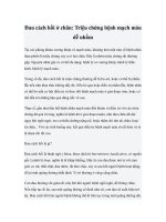
The shuttle lock system uses a gel
or silicone liner with a locking pin on
the bottom, which is rolled onto the
skin. The pin is then inserted into a
shuttle lock inside the socket (Fig. 1).
This system helps to provide for a
total-contact fit, which minimizes
distal edema, distributes pressure
over the entire limb, and prevents
movement of the limb against the
socket. The coefficient of friction be-
tween the stump-liner interface and
the liner-socket interface needs to be
high to minimize any movement be-
tween the surfaces. The soft, flexible
gel liners can accomplish this.
16,18
In
fact, indications for these systems in-
clude patients whose skin is sensitive
to shear forces and uncontrolled pis-
toning in the socket.
15
Because of the
potential for skin breakdown and sub-
sequent infection, pistoning is a
threat to further loss of limb to an
amputee with vascular disease or di-
abetes. Prosthetic socks can be added
to the shuttle lock system in the
event of limb girth fluctuations.
The shuttle lock system is appro-
priate for all levels of users because
of the security afforded by this sus-
pension method as well as the im-
proved cosmesis and ease of don-
ning. When the transfemoral
residual limb is long, there may be a
difference between the involved
limb and the sound limb in the knee
centers of rotation when the locking
hardware is placed inside the pros-
thesis.
15
The shuttle lock system is
an excellent alternative for users
who have difficulty donning the full
suction socket.
19
Suction is a popular means of sus-
pension, particularly for the patient
with a transfemoral amputation. It
provides for an intimate fit between
the limb and the socket, which en-
hances proprioception and muscular
control of the prosthesis.
20
Comfort
level is also enhanced because auxil-
iary suspension, such as a belt, waist
strap, or thigh corset, is not needed,
although an additional means of sus-
pension may be used when a higher
activity level requires it. The socket
is held on through negative pressure
and surface tension. Because the pa-
tient must stand to ensure that the
limb is fully entered into the socket,
patients with poor balance or prob-
lems with manual dexterity may
have difficulty donning this type of
socket.
15,19
Total suction is not often
used with the transtibial prosthesis
because the bony characteristics of
the lower limb make it difficult to
obtain a tight seal.
Prosthesis Construction
Traditional Construction
In the past, prostheses were fabri-
cated in an exoskeletal fashion: the
strength of the prosthesis derived
from the solid outer walls. Exoskel-
etal prostheses were composed of a
solid piece of wood or rigid polyure-
thane covered with plastic laminate
and fashioned into the shape of a leg.
The components were embedded or
built-in and thus were not inter-
changeable.
21
Unless an external
frame was used, the entire prosthesis
needed to be refabricated to change
componentry. In addition, these
prostheses were heavy and bulky.
Exoskeletal prostheses are not usual-
ly fabricated today unless a user spe-
cifically requests such construction;
some long-term prosthesis users
have become accustomed to the
exoskeletal design and opt not to
change.
Contemporary
Construction
Today, most prostheses are of an
endoskeletal design: components are
located inside the prosthesis. The
strength of the prosthesis comes
from the pylon—usually made of
lightweight nylon, aluminum, or
carbon/graphite—which is enclosed
in a cosmetic foam covering. Bene-
fits of the endoskeletal design are
that components of a standardized
design are completely interchange-
able, the prosthesis is easily repaired,
and the design is lighter and more
cosmetic than the exoskeletal de-
sign.
21
However, these prostheses are
subject to external moisture and de-
bris.
Figure 1
A, Liner with attached pin for shuttle lock mechanism. B, Shuttle lock mechanism in
clear check socket.
Karen Friel, PT, DHS
Volume 13, Number 5, September 2005 329
Transtibial Prostheses
The prosthetic socket has several
important functions. It is designed
to accommodate the residual limb,
allow for weight bearing, distribute
forces, and provide total contact to
prevent distal pooling of fluid with-
in the residual limb. The sockets are
custom-fitted and have specific areas
of weight bearing incorporated into
their design.
Traditional Socket Design
Since the 1950s, the most com-
mon socket design has been patellar
tendon–bearing (PTB), still consid-
ered the standard today.
16
The design
is based on increasing weight-
bearing pressures in areas that are
pressure tolerant. These areas in-
clude, but are not restricted to, the
patellar tendon, medial and lateral
tibial flares, and gastrocnemius-
soleus complex. Conversely, the
socket is designed to decrease pres-
sures in areas that are pressure-
sensitive, such as the proximal and
distal fibula and the tibial crest.
Contemporary Socket
Design
With the advent of new materials
and fabrication principles, an in-
creasingly common adjunct to the
PTB design is the use of hydrostatic
loading. Hydrostatic loading stabiliz-
es the bony anatomy within the soft
tissues through the use of compres-
sion and elongation of the tissues
during casting for the socket. The
forces of weight bearing are distrib-
uted through a greater surface area,
thus decreasing pressures to any one
area. This technique is also known
as total-surface bearing; the force is
evenly distributed throughout the
entire limb.
16
This distribution may
help to prevent breakdown of the
skin and enhance comfort for the
user.
Foot/Ankle Assembly
Advances in the design of pros-
thetic feet are occurring at a dramat-
ic rate, and new feet are introduced
to the market regularly. Numerous
factors must be considered when fit-
ting a prosthetic foot (Table 2). The
most notable factor related to the be-
havior of the prosthetic foot is the
presence or absence of a joint that al-
lows for plantar flexion. This factor
is significant because the ability to
have both plantar flexion and dorsi-
flexion range of motion forms the
basis for the classification system of
articulated and nonarticulated ankle
designs.
24
Many of the newer designs
have an integrated pylon/ankle/foot
mechanism, which allows for both
dorsiflexion and energy return to the
user.
It should be noted that there is no
difference between the prosthetic
feet used for transtibial prostheses
and those used for transfemoral pros-
theses. The choice of foot depends
on the patient’s mobility, stability,
and functional use and control of the
prosthesis.
Non–Dynamic Response
Feet
The solid ankle cushioned heel
(SACH) foot (Sheck and Siress, Chi-
cago, IL) (Fig. 2) has been extremely
popular since its inception in the
1950s and is very economical com-
pared with other prosthetic feet. The
SACH foot uses compressible mate-
rial in the heel to simulate plantar
flexion at heelstrike. It incorporates
a rigid, wooden keel that is unable to
dorsiflex through the midstance
phase of gait. Because of this, during
midstance, the center of mass on the
prosthetic side is comparatively
higher than on the nonamputated
side. This inequity leads to increased
loads placed on the sound side during
the weight acceptance phase of gait;
25
instead of the normally smooth tran-
sition provided by adequate dorsiflex-
ion, the user tends to “fall onto” the
sound side during weight transfer.
Studies have shown that ambulating
with the SACH foot produces the
greatest ground reaction forces on the
sound side compared with both dy-
namic response feet and other non–
dynamic response feet.
26,27
This
means that the SACH foot is not op-
timal at protecting the sound limb
from excessive forces, which is a con-
cern because of the high rate of con-
tralateral amputation in the popula-
tion with diabetes.
2
However, the
Key Concepts for Foot Prescription
Ability to adequately absorb impact
forces
Ability to accommodate to uneven
terrain
Avoidance of the prosthesis being
too heavy distally
22
Dynamic response of the foot (ie,
ability to return energy to the user
during push-off
23
)
Maintenance of proper balance
Table 2 Figure 2
Solid ankle cushioned heel (SACH) foot.
Componentry for Lower Extremity Prostheses
330 Journal of the American Academy of Orthopaedic Surgeons
SACH foot is still appropriate for the
limited ambulator, the K-1 level user,
and the individual in the beginning
stages of rehabilitation. One major ad-
vantage of using this type of pros-
thetic foot is that the rigid keel may
provide more balance than would a
dynamic response foot.
6
Feet specifically designed for the
geriatric patient have keels com-
posed of flexible polypropylene. This
design replicates a more pronated
position of the foot, with more of the
foot in contact with the ground. This
factor provides for added stability
and a softer rollover, thus minimiz-
ing forces to the residual limb.
5
The
Dycor ADL uniaxial design (Dycor,
Missouri City, TX) is currently cat-
egorized for the K-2 level user.
Dynamic Response Feet
Currently, the more responsive
prosthetic feet are generally reserved
for the more active ambulators.
These feet are available in both artic-
ulated and nonarticulated designs.
The dynamic response foot uses a
keel that deforms under pressure but
returns to its original shape when
the load is removed. The keel acts as
a spring that on return to its original
shape returns energy to the user,
thereby assisting push-off. The flex-
ibility of the keel allows for dorsi-
flexion.
6
The increased dorsiflexion
afforded by the dynamic response
foot allows for a longer midstance
time in the gait cycle. Hafner et al
28
noted that increased time spent in
midstance may increase the percep-
tion of stability, compared with the
rapid heel rise and toe-only support
in the non–dynamic response foot.
Hafner et al
28
compared patient
perception of energy-storing feet ver-
sus their perception of conventional
prosthetic feet using biomechanical
gait analysis. Results indicated that,
despite advantages perceived by us-
ers when ambulating with a dynam-
ic response foot, supportive biome-
chanical data were inconsistent. The
advantages that users reported when
ambulating at higher velocities with
a dynamic response foot were in-
creased gait velocity, increased sta-
bility, increased ankle motion, de-
creased shock at the hip and knee,
and enhanced performance in “high
activity” gait (ie, activities requiring
increased ankle power and propul-
sion).
28
The impact that foot selection has
on forces taken through the sound
limb also has been investigated. Spe-
cifically, the Flex-Foot (Össur, Aliso
Viejo, CA) (Fig. 3) was compared to
SACH, Carbon Copy II (Ohio Willow
Wood, Mt. Sterling, OH), Seattle
(Model and Instument W orks, Seattle,
WA), and Quantum (Hosmer Dor-
rance Corp, Campbell, CA) feet. The
Flex-Foot notably reduced peak ver-
tical ground reaction forces to the
sound limb compared with the other
feet. In fact, the other feet on average
increased peak forces to the sound
limb 17% over normal values. The
authors therefore hypothesized that
the increased dorsiflexion achieved
with the Flex-Foot design allows for
less of a fall onto the sound limb dur-
ing the weight-acceptance phase of
gait.
26
All of the dynamic response
feet are usually prescribed for the K-3
or K-4 level ambulator.
Several shock absorbers are avail-
able, many of them built into the an-
kle mechanism of the foot/ankle as-
sembly. The Reflex Vertical Shock
Pylon (VSP) (Össur), is a variation of
the Flex-Foot, with the vertical shock
absorber built into the ankle mech-
anism.
5
Results of a study by Hsu et
al
29
indicated that the Reflex VSP al-
lowed for improved energy cost and
gait efficiency compared with the
SACH foot or Flex-Foot. Specifically
addressing gait parameters, Miller
and Childress
30
found that vertical
compliance of the pylon caused little
change in gait parameters during nor-
mal speeds of walking. With the Re-
flex VSP system, greater changes
were noted in ground reaction forces,
vertical trunk displacement, and py-
lon compression at faster walking
and jogging speeds compared with
normal walking speeds. The most re-
cent version of this foot is called the
Ceterus (Össur) (Fig. 4).
Transfemoral
Prostheses
The design principles for the trans-
femoral socket are similar to those for
the transtibial socket. Currently,
there are three primary designs. The
plugfit original sockets for transfem-
oral prostheses were cylindrical and
used the soft tissues of the thigh for
weight bearing. Today’s sockets,
whether the traditional quadrilateral
socket or more contemporary ischial
containment or flexible sockets, all
feature some level of shared weight
bearing between the skeleton of the
pelvis and the soft tissues of the thigh.
Traditional Socket Design
Quadrilateral design sockets first
appeared in the 1950s. They are so
named because each of the four
walls of the socket has distinct
features to apply forces and distrib-
ute pressures. Weight bearing is
achieved primarily through the is-
chial tuberosity and gluteal muscu-
lature sitting atop a posterior shelf.
This socket provides for lateral sta-
bilization of the femur to assist with
pelvic stability.
19
Figure 3
Flex-Foot, an integrated pylon/ankle/
foot.
Karen Friel, PT, DHS
Volume 13, Number 5, September 2005 331
Critics have suggested that use of
this socket results in skin irritation
in the ischium and pubis, tender-
ness over the anterior distal femur,
and discomfort from the anterior
wall when sitting, as well as poor
cosmesis and a tendency toward a
Trendelenburg-type gait.
31
This de-
sign is rarely used today.
Contemporary Socket
Design
The ischial containment socket
design, the current standard (Fig. 5),
resulted from addressing some of the
criticisms of the quadrilateral sock-
et. Specifically, certain parameters
regarding transfemoral socket fit in-
corporate the design principles of the
ischial containment socket devel-
oped in 1987 by the International
Society for Prosthetics and Orthot-
ics
19
(Table 3). This design emphasiz-
es maintaining adequate femoral ad-
duction for enhanced pelvic stability
and improved gait. Improved force
distribution and stability are empha-
sized by having more of the pelvis
housed within the socket rather
than sitting on top of the socket, as
in the quadrilateral design.
20,31
The flexible above-knee socket
(also known as the Icelandic, Scandi-
navian, or New York socket), while
still employing ischial containment
principles, incorporates a flexible in-
ner socket supported by a rigid out-
er frame with cut-out sections
31
(Fig.
6). This design minimizes pressures
within the socket of contracting
muscles and soft tissues. All of these
socket designs can be used with any
type of suspension.
Knees
The variable that determines
which knee is appropriate for
each functional K-level is whether
the knee allows for a fixed pendu-
lum swing or a variable cadence of
Figure 5
Ischial containment socket. Overhead view.
Figure 4
Left, Reflex VSP with integrated shock absorption. Right, Ceterus with integrated
shock absorption.
Design Principles of the
Transfemoral Socket
19
Maintain normal femoral adduction
and narrow-based gait
Enclose the ischial tuberosity and
ramus within the socket to create a
skeletal lock
Distribute forces along the shaft of
the femur
Decrease emphasis on a narrow
anterior-posterior diameter
Provide total contact
Use suction suspension when
possible
Table 3
Componentry for Lower Extremity Prostheses
332 Journal of the American Academy of Orthopaedic Surgeons
swing. A fixed-swing rate control
knee is appropriate for K-1 and K-2
level functional ambulators. The
unlimited community ambulators,
K-3 and K-4 users, are capable of us-
ing a variable-cadence swing mech-
anism (Table 1). This category of
prosthesis uses both hydraulic and
pneumatic mechanisms to control
the rate of swing.
7
Fixed-Cadence Knee
Mechanisms
Conventionally damped pros-
thetic limbs use fixed resistance in
the knee unit to control the pendu-
lum action of the prosthesis. This
rate of swing is set by the prosthet-
ist. When the cadence of gait
changes, the user must compensate
for the fixed pendulum speed by us-
ing gait deviations to change the rate
of extension or by forcefully throw-
ing the limb forward to ensure that
the foot will be in the correct loca-
tion at heel strike.
7
Many of these
knees have a stance lock control so
that the knee will not buckle during
stance. This is useful for the patient
who has poor prosthetic control and
balance or for the K-1 and K-2 level
ambulator.
Variable-Cadence Knee
Mechanisms
Variable-cadence knees use pneu-
matics or hydraulics to accommo-
date to the user’s walking speed. The
range of velocities of swing rate set
into the unit is dependent on the us-
er’s typical level of functioning. The
ambulator is free to change walking
speed within that range and still
avoid gait deviations.
One option available to the user is
the addition of a stance flexion com-
ponent. In normal gait, the stance
knee will flex approximately 15° to
18° as load is transferred onto the
weight-bearing leg. This lowering of
the center of mass allows for a de-
creased load on the limb
7
as well as
a cushioned support with a gradual
weight transfer onto the sound limb.
32
Given the propensity for contralateral
limb loss in patients with vascular
disease or diabetes, decreasing the
loads placed on the sound limb may
help to prolong and protect the health
of that limb. Stance flexion devices
incorporate some degree of flexion
during stance. They have been devel-
oped to decrease load as well as to add
stability during gait by lowering the
center of mass. For the patient with
potential proprioceptive difficulties,
this could be advantageous for the
safety and efficiency of gait. In addi-
tion, some degree of stance control is
favorable for the more active person
with a lower limb amputation when
put into compromising situations for
which additional stability may be
necessary.
7
A computer-assisted knee mech-
anism uses a computer chip im-
planted into the hydraulic knee unit
to accommodate to the walking
speed of the user. This allows for
correction and control of the knee
continuously throughout the gait
cycle—up to 50 times per second
with little or no thought required
by the prosthesis user—to ensure
proper swing rate and stance con-
trol.
7
Hence, there is no need to
compensate with gait deviations.
33
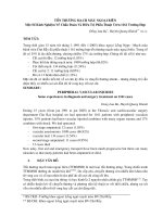
Computer-assisted knees (eg, the
C-leg [Otto Bock, Minneapolis, MN]
and the Intelligent Knee [Endolite,
Centerville, OH]) can assume part of
the energy-absorbing functions of
the quadriceps and hamstrings nor-
mally seen during early and late
swing phases of gait
11
(Fig. 7). Be-
cause these knees allow for variable
cadence, they would be appropriate
only for the high activity−level
user—K-3 or K-4 on the K-rating
scale. The expense of these knees is
not warranted for the more limited
ambulator who is unable to benefit
from its advantages.
Datta and Howitt
34
compared
user satisfaction and overall use
when ambulating with a pneumatic
swing phase–control knee versus a
microprocessor-controlled intelli-
gent knee. Using a questionnaire for-
mat, they found that most users pre-
ferred the microprocessor-controlled
knee unit. In fact, 95% reported
walking at different speeds to be “a
lot easier” or “easier.” More than
81% said they could walk farther,
and 59% found walking on slopes
and hills “a lot easier.” An over-
whelming 95% felt that walking
was more nearly “normal.″
34
Figure 6
Left, Flexible above-knee socket. Right, Outer socket for flexible system.
Karen Friel, PT, DHS
Volume 13, Number 5, September 2005 333
Studies addressing energy expen-
diture show that at gait velocities
>3.2 km/h, a decrease in energy ex-
penditure of approximately 10% oc-
curred when ambulating with a mi-
croprocessor knee compared with
ambulation using a conventional
knee prosthesis.
33,35
A common re-
port of the elderly prosthesis user is
that the leg feels “heavy” or that the
prosthesis is too fatiguing to use. A
knee that can markedly decrease en-
ergy expenditure may have consider-
able implications for the overall ac-
tivity level, health, and well-being of
the patient.
Summary
Rapid advances in prosthesis tech-
nology have led to an expansion of
prosthetic options for individuals
with transtibial and transfemoral
amputations, regardless of cause of
the amputation. These options may
be grouped into classes of compo-
nents, which can then be viewed in
the context of the needs of users
with different functional levels. Re-
gardless of the functional level of
the user, contemporary prostheses
generally use endoskeletal con-
struction, sockets that emphasize
total contact, and weight distribu-
tion between bony structures and
soft tissues. Such prostheses also
use suspensions that minimize the
use of constrictive belts and cuffs
proximal to the level of amputation.
For individuals expected to be
household ambulators or limited
community ambulators, tradi-
tional, non–dynamic response pros-
thetic feet and fixed-cadence knees
may be appropriate. For individuals
who are expected to be unlimited
community ambulators, or for those
who will place high work or recre-
ational demands on their prosthe-
ses, contemporary dynamic re-
sponse feet and variable-cadence
knees should be prescribed.
Specific considerations exist for
persons with peripheral vascular dis-
ease. One primary concern is preser-
vation of the intact limb, which can
be improved by components that
help to lower the center of mass as
well as ease weight transfer onto the
sound limb. Second, skin integrity is
equally important and can be aided
by liners composed of gel, silicone,
or similar materials that serve to de-
crease shear and dissipate friction
forces. The physician, therapist,
prosthetist, and patient should all be
actively engaged in the decision-
making process.
Acknowledgment
The author wishes to thank Eliza-
beth Domholdt, PT, EdD, for her as-
sistance with significant revisions of
this manuscript.
References
1. Gailey RS: One Step Ahead: An Inte-
grated Approach to Lower Extremity
Prosthetics and Amputee Rehabilita-
tion. Miami, FL: Advanced Rehabili-
tation Therapy, 1994.
2. Reiber GE, Boyko EJ, Smith DG: Lower
extremity foot ulcers and amputations
in diabetes, in Diabetes in America,
ed 2. Washington, DC:National Insti-
tutes of Health, 1995, pp 409-427.
Available at www.niddk.nih.gov/
health/diabetes/dia/contents.htm Ac-
cessed July 20, 2005.
3. Collin C, Collin J: Mobility after
lower-limb amputation. Br J Surg
1995;82:1010-1011.
4. McWhinnie DL, Gordon AC, Collin J,
Gray DW, Morrison JD: Rehabilita-
tion outcome 5 years after 100 lower-
limb amputations. Br J Surg 1994;81:
1596-1599.
5. Nassan S: The latest designs in pros-
thetic feet. Phys Med Rehabil Clin N
Am 2000;11:609-625.
6. Romo HD: Specialized prostheses for
activities: An update. Clin Orthop
1999;361:63-70.
7. Romo HD: Prosthetic knees. Phys Med
Rehabil Clin N Am 2000;11:595-607.
8. Gailey RS, RoachKE, ApplegateEB, et
al: The amputee mobility predictor:
An instrument to assess determi-
nants of the lower-limb amputee’s
ability to ambulate. Arch Phys Med
Rehabil 2002;83:613-627.
9. Gailey RS, Nash MS, Atchley TA, et
al: The effects of prosthesis mass on
metabolic cost of ambulation in non-
vascular trans-tibial amputees. Pros-
thet Orthot Int 1997;21:9-16.
10. Selles RW, Bussmann JB, Wagenaar
RC, Stam HJ: Effects of prosthetic
mass and mass distribution on kine-
matics and energetics of prosthetic
gait: A systematic review. Arch Phys
Med Rehabil 1999;80:1593-1599.
11. Rietman JS, Postema K, Geertzen JH:
Gait analysis in prosthetics: Opin-
ions, ideas and conclusions. Prosthet
Orthot Int 2002;26:50-57.
12. Coleman KL, Boone DA, Smith DG,
Czerniecki JM: Effect of trans-tibial
prosthesis pylon flexibility on ground
reaction forces during gait. Prosthet
Orthot Int 2001;25:195-201.
13. Postema K, Hermens HJ, de Vries J,
Koopman HF,Eisma WH:Energy stor-
age and release of prosthetic feet: I.
Biomechanical analysis related to
user benefits. Prosthet Orthot Int
1997;21:17-27.
14. Nielsen DH, Shurr DG, Golden JC,
Meier K: Comparison of energy cost
and gait efficiency during ambulation
in below-knee amputees using differ-
ent prosthetic feet—a preliminary
report. Journal of Prosthetics and
Orthotics 1989;1:24-31.
15. Kapp S: Suspension systems for pros-
theses. Clin Orthop 1999;361:55-62.
16. Edwards ML: Below knee prosthetic
Figure 7
Otto Bock computerized leg C-leg.
(Courtesy of Otto Bock Health Care,
Minneapolis, MN.)
Componentry for Lower Extremity Prostheses
334 Journal of the American Academy of Orthopaedic Surgeons
socket designs and suspension sys-
tems. Phys Med Rehabil Clin N Am
2000;11:585-593.
17. Geertzen JH, Martina JD, Rietman
HS: Lower limb amputation: II. Reha-
bilitation—a 10 year literature re-
view. Prosthet Orthot Int 2001;25:14-
20.
18. Emrich R,Slater K:Comparative anal-
ysis of below-knee prosthetic socket
liner materials. J Med Eng Technol
1998;22:94-98.
19. Kapp SL: Transfemoral socket design
and suspensionoptions. PhysMed Re-
habil Clin N Am 2000;11:569-582.
20. Dingwell JB, Davis BL, Frazier DM:
Use of an instrumented treadmill for
real-time gait symmetry evaluation
and feedback in normal and trans-
tibial amputee subjects. Prosthet
Orthot Int 1996;20:101-110.
21. May BJ: Prosthetic components, in
Amputations and Prosthetics: A Case
Study Approach. Philadelphia, PA:
F.A. Davis Co, 1996, pp 118-159.
22. Lehmann JF, Price R, Okumura R,
Questad K, de Lateur BJ, Négretot A:
Mass and mass distribution of below-
knee prostheses: Effect on gait effica-
cy and self-selected walking speed.
Arch Phys Med Rehabil 1998;79:162-
168.
23. Fergason JR, Boone DA: Custom de-
sign in lower limb prosthetics for ath-
letic activity. Phys Med Rehabil Clin
NAm2000;11:681-699.
24. Cortés A, Viosca E, Hoyos JV, Prat J,
Sánchez-Lacuesta J: Optimisation of
the prescription for trans-tibial (TT)
amputees. Prosthet Orthot Int 1997;
21:168-174.
25. Lehmann JF, Price R, Boswell-
Bessette S, Dralle A, Questad K: Com-
prehensive analysis of dynamic elas-
tic response feet: Seattle Ankle/Lite
Foot versus SACH foot. Arch Phys
Med Rehabil 1993;74:853-861.
26. Powers CM, Torburn L, Perry J,
Ayyappa E: Influence of prosthetic
foot design on sound limb loading in
adults with unilateral below-knee
amputations. Arch Phys Med Rehabil
1994;75:825-829.
27. Hayden S, Evans R, McPoil TG, Corn-
wall MW, Pipinich L: The effect of
four prosthetic feet on reducing plan-
tar pressures in diabetic amputees.
Journal of Prosthetics and Orthotics
2000;12:92-96.
28. Hafner BJ, Sanders JE, Czerniecki J,
Fergason J: Energy storage and return
prostheses: Does patient perception
correlate with biomechanical analy-
sis? Clin Biomech (Bristol, Avon)
2002;17:325-344.
29. Hsu MJ, Nielsen DH, Yack HJ, Shurr
DG: Physiological measurements of
walking and running in people with
transtibial amputations with 3 differ-
ent prostheses. J Orthop Sports Phys
Ther 1999;29:526-533.
30. Miller LA, Childress DS: Analysis of a
vertical compliance prosthetic foot.
J Rehabil Res Dev 1997;34:52-57.
31. Esquenazi A, Leonard JA Jr, Meier RH
III, Hicks JE, Fisher SV, Nelson VS:
Prosthetics, orthotics, and assistive
devices: III. Prosthetics. Arch Phys
Med Rehabil 1989;70:S206-S209.
32. Cochrane H, Orsi K, Reilly P: Lower
limb amputation: III. Prosthetics a
10 year literature review. Prosthet
Orthot Int 2001;25:21-28.
33. Taylor MB, Clark E, Offord EA, Baxter
C: A comparison of energy expendi-
ture by a high level trans-femoral am-
putee using the Intelligent Prosthesis
and conventionally damped prosthet-
ic limbs. Prosthet Orthot Int 1996;20:
116-121.
34. Datta D, Howitt J: Conventional ver-
sus microchip controlled pneumatic
swing phase control for trans-femoral
amputees: User’s verdict. Prosthet
Orthot Int 1998;22:129-135.
35. Buckley JG, Spence WD, Solomonidis
SE: Energy cost of walking: Compari-
son of “Intelligent Prosthesis” with
conventional mechanism. Arch Phys
Med Rehabil 1997;78:330-333.
Karen Friel, PT, DHS
Volume 13, Number 5, September 2005 335