Cardiac Catheterization in Congenital Heart Disease: Pediatric and Adult - Part 9 doc
Bạn đang xem bản rút gọn của tài liệu. Xem và tải ngay bản đầy đủ của tài liệu tại đây (650.53 KB, 95 trang )
CHAPTER 28 Atrial septal defect occlusion
749
When satisfied with the configuration and the position
on the septum by both fluoroscopy and by TEE or ICE, the
security of the fixation in the septum is “tested” by means
of a moderately vigorous, to and fro, push–pull on the
delivery cable/devicea the so called “Minnesota wiggle”.
When both disks are positioned properly on and fixed
securely in the septum and as traction is applied to the
cable and the device, which is fixed securely in the sep-
tum, the right and left atrial disks separate from each
other with each pull. As the disks are separated, the rim of
septal tissue that is between the disks is seen even more
clearly on the TEE or ICE. As the cable is pushed during
the “wiggle”, the right and left atrial disks are pushed
together, but still should have some distance between the
opposing edges of the disks and should not push through
and/or away from the septal defect. The entire circumfer-
ence of the device is scrutinized with the TEE or ICE
during the “wiggle” to verify that the septal rim is “sand-
wiched” between the two disks all of the way round the
device. A small hand angiogram, with an injection through
the separate catheter positioned close to or against the right
sided disk of the device demonstrates the alignment of the
device relative to the septum and helps to demonstrate if
part of either disk is on the wrong side of the septum.
Rarely, as the left atrial disk and the central hub are
extruded from the sheath, the left atrial side does not form
a “disk”, but rather extrudes in an elongated, spiral or
“cobra” configuration. This abnormal configuration usu-
ally persists even after the hub and right disk are com-
pletely out of the delivery sheath. The exact etiology of
this deformation probably is related to how the “wires”
of the Nitinol™ weave expand from their elongated
configuration relative to each other and/or may be related
to excessive torquing of the device and cable while they
were still within the sheath. Usually patience is all that is
necessary and the device gradually resumes its normal
configuration. If the abnormal configuration persists, the
device and sheath are moved forward slightly and/or the
device is withdrawn into the sheath and the deployment
repeated. Rarely, even with repeated withdrawal and
redeployment, the deformity persists. In that case the
sheath is advanced back into the left atrium over the
device and the device is withdrawn out of the body. If
the device still has the deformed configuration after it is
withdrawn from the sheath, the device is manually elon-
gated by traction on both hubs and then released to allow
it to re-form its “resting”, flat configuration. In this oper-
ator’s experience, the device always has resumed its nor-
mal configuration with this maneuver outside of the body.
Once it returns to its normal shape, the same device can be
reloaded and redeployed successfully.
A major advantage of the Amplatzer™ ASD device
is that any time before it is released purposefully, it very
easily can be withdrawn back into the delivery sheath. If
the device is not sized accurately, if it is malpositioned in
the defect, or if it pulls through the defect at any stage of the
delivery, the device easily can be withdrawn back into the
sheath. The sheath then can be repositioned through the
defect where the same device can be reimplanted or the
original device is removed completely and a new device
delivered through the same sheath. If necessary for any
reason, the withdrawal into the sheath and redeployment
can be accomplished multiple times. However, the more
times a device is pulled into the sheath and redeployed,
the more likely the sheath is to be distorted, the delivery
cable unwound from the device and/or the device dis-
torted permanently.
Once the device is fixed securely within the septum
with a satisfactory position of the device in the septal
defect and there is no significant residual leak, the
device/cable is prepared for release. The torquing hub is
attached firmly to the proximal end of the delivery cable
by introducing the end of the delivery cable as far as pos-
sible into the open hole in the torquing hub, and then
tightening the small set screw that is on the side of the
torquing hub onto the cable. The device is uncoupled from
the delivery cable by many, rapid, counterclockwise turns
of the delivery cable using the torquing device. It usually
takes 6 to 7 complete counterclockwise turns of the cable
to unscrew the delivery cable from the proximal hub of
the device. During all of the time when the device is being
unscrewed, the device/cable should be observed on
fluoroscopy or, preferably, recorded on biplane stored
fluoroscopy to be sure that the device is not bound abnor-
mally to the cable and/or is not being distorted in the
septum during the unscrewing process. As the device
unscrews completely and becomes free of the cable, it usu-
ally moves away from the cable and realigns its position
significantly, as it reorients itself more properly into the
plane of the septum (Figure 28.11). This movement can be
quite extensive and sudden. After the device is released
and reoriented on the septum, the position of the device
and the presence of any residual leaks are scrutinized by
TEE or ICE.
In order to offset the pressure effects of the shunt vol-
ume, which has become “trapped” suddenly in the left
heart (and left atrium in particular) and until the total cir-
culation has had time to “redistribute this volume”,
patients with very large defects and/or minimal circum-
ferential rims are given 0.25–0.5 mg/kg of furosemide
intravenously immediately prior to the implant of the
device. The heparin given during the case is not reversed
at the end of the case. All patients are given an intra-
venous dose of a cephalosporin at the time of the implant
of the device and two or three more intravenous doses
at intervals of 6 or 8 hours before discharge from the
CHAPTER 28 Atrial septal defect occlusion
750
hospital. The patients are discharged on aspirin, 81 mg/day,
which is to be continued for 6 months and with instruc-
tions to utilize bacterial endocarditis prophylaxis at times
of high risk to bacteremia during that same 6 months.
In the United States, the Amplatzer ASD™ device
underwent a regulated FDA, IDE clinical trial and com-
pleted a one-year follow-up of the implanted devices
in early 2001. The Amplatzer™ ASD occlusion devices
received FDA approval for the elective transcatheter
occlusion of the secundum ASD in the US in September
of 2001, and the final notification of approval was received
in December 2001. This is the first implantable intracar-
diac device ever approved by the FDA for elective clinical
use specifically in a congenital heart lesion and in pedi-
atric patients.
Excessive Eustachian valve and the Amplatzer™
device
Although the Amplatzer™ ASD device has no legs
that can spring open into the right atrium and that, in
turn, could catch on a redundant Eustachian valve, there
still are potential problems with the delivery of the
Amplatzer™ ASD devices in the presence of excessive
Eustachian valve tissue. The redundant Eustachian valve
tissue usually is seen as a very flexible structure, which
flops in and out of the echo field adjacent to the atrial sep-
tum and atrial septal defect. The most common problem
with the Amplatzer™ ASD device and the Eustachian
tissues occurs as the delivery cable is being unscrewed
during the release of the cable from the device. The mod-
erately rough surface of the rotating, exposed cable can
tangle with the Eustachian tissue and, when it does, it
winds the redundant tissue around the delivery cable.
When the cable becomes entangled during the release
of the device, the Eustachian tissue sometimes can be
untangled by rotating the cable in a clockwise direction
after the release of the device, although this can wind the
Eustachian tissue even tighter around the cable and wind
it in both directions. When the Eustachian tissue becomes
entangled around the cable, the sheath is advanced over
the cable and the cable is withdrawn forcefully into the
delivery sheath along with part of the Eustachian valve.
As with most complications, prevention of the problem
is preferable. When the Eustachian tissue is noticed in
close proximity to the device and cable and after the secure
deployment of the device, the long sheath is re-advanced
carefully over the cable and back against the surface of the
right atrial disk before the cable is unscrewed from the
device. The sheath covers the cable, “separates” the rotat-
ing cable from the Eustachian valve tissues and prevents
cable entrapment.
Very extensive, redundant Eustachian tissue also can
become entangled in the mesh of the central hub and/or
proximal (right atrial) disk of the device, particularly
as the device is rotated and/or as the open mesh of the
right atrial disk is extruded. If the Eustachian tissue
remains entangled on the device and is unrecognized,
it creates a partial “diaphragm” across the entrance of
the inferior vena cava. The amount of obstruction from
this tissue depends upon the density and extent of the
Eustachian tissue.
When the Eustachian tissue remains attached to the
device after the release of the device, the entangled
Eustachian tissue can be separated from the device using
a large angioplasty or static sizing balloon. The balloon
catheter is maneuvered between the Eustachian tissue and
device using TEE or ICE guidance and once positioned
between the tissues, the balloon is inflated. This maneu-
ver may have to be repeated several times to free the
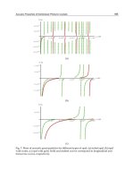
Figure 28.11 Amplatzer™ ASD device fully deployed and released. Torsion
from cable is released. Device flattens and aligns exactly on septum with the
central hub opened fully and fixing the device in the septal defect.
CHAPTER 28 Atrial septal defect occlusion
751
Eustachian tissues totally. It always is prudent to avoid
the entanglement when Eustachian tissue is present.
In every case of a potential occlusion of an ASD with
a catheter-delivered device, the right atrium should
be scrutinized thoroughly for long and/or redundant
Eustachian valve tissue by TEE or ICE. When encoun-
tered, the Eustachian valve tissue can be trapped and
“moved away” from the defect with a deflector catheter
as described later in this chapter in the discussion of
the CardioSEAL™ and STARFlex™ devices, where the
Eustachian valve is even more of a problem.
Retrieval of the Amplatzer™ ASD device
One of the major advantages of the Amplatzer ASD
Device™ is the ability to be withdrawn back into the
delivery sheath, easily, and at any time, before the purpose-
ful release of the device from the delivery cable. This
withdrawal back into the sheath and redeployment of the
device can be repeated many times if necessary. This of
course holds true, not only for repositioning the device on
the septum, but for removing the device completely if
a perfect implant on the septum is not achieved or if the
device pulls completely through the septum. The with-
drawal is accomplished by placing tension on the delivery
cable while the sheath is advanced simultaneously over
the device and while withdrawing the device. These
maneuvers re-elongate the device similar to the procedure
for its loading.
Occasionally, the distal end of the delivery sheath
becomes distorted (accordioned) with repeated with-
drawal and redeployment of the device and eventually
even the still attached, but deployed and malpositioned
Amplatzer™ device cannot be withdrawn into the ori-
ginal, distorted sheath. The Amplatzer™ system has a
unique recovery wire/sheath/dilator exchange system
for just such an occurrence. The proximal end of every
standard Amplatzer™ delivery cable has a small hub with
a female screw socket in the hub, which is identical to the
socket in the hub on the device. This screw socket allows a
second delivery cable to be attached to the proximal end of
the original cable, which, in turn, produces an “exchange
length” delivery cable! The dilator of the recovery sheath/
dilator has an extra large lumen and distal opening, which
accommodates the diameter of the delivery cable.
The “exchange length” cable allows the original dam-
aged sheath to be withdrawn over the “exchange cable”
and completely out of the body while the device still is
open and attached to the original part of the cable within
the heart. Once the damaged sheath is removed, the
“recovery” sheath/dilator with the larger lumen of the
special dilator is advanced over the “exchange cable” to a
position adjacent to the still attached device. The dilator
is removed from the new sheath over the cable and the
system is cleared meticulously of air and/or clot by allow-
ing free back-flow from the sheath. The back-bleed/flush
valve is reintroduced over the “exchange” cable, attached
to the new sheath and the system is flushed. With the new
sheath in place, the still attached Amplatzer™ occlusion
device is readily withdrawn into the new, undamaged
sheath.
Once the device has been released from the cable,
retrieval of the Amplatzer™ device still is possible, but
not as easily, nor as predictably, as before its release
15
. The
possibility of a device embolization should always be
included in the “pre-catheterization” discussion with the
patient/parents. Along with the potential for emboliza-
tion, the possible need for surgical retrieval should always
be presented to the patient/parents.
The key element to retrieval of an embolized
Amplatzer™ ASD occluder is to re-catch the device by the
central metal attachment “post” on the right atrial disk of the
device. This is accomplished using a 10 mm Microvena™
snare and snare catheter passed through a very large
diameter long sheath. The long sheath that is used for the
retrieval of an Amplatzer™ ASD occluder should be at
least two French sizes larger than the original delivery
sheath and the retrieval sheath should be as stiff as pos-
sible. A long sheath that is even larger than two French
sizes larger than the original delivery sheath is even more
advantageous. If the fully released device is not still on the
septum or, at least, is not in an orientation within the heart
and/or great artery with the right atrial “hub” facing the
retrieval catheter, the errant device must be reoriented in
the vessel or chamber using another catheter and/or wire
in order to make the central “post” accessible to the loop of
the snare. This reorientation is performed with a separate
catheter, often approaching the device from the superior
vena cava or even an artery when the device is lodged on
the left side of the septum. The orientation of the device
can be changed using an active deflector wire and/or a
bioptome forceps to grasp an edge of the device in order to
turn and/or hold it while the right sided post is grasped
by the snare, which has been introduced through the
large, long recovery sheath. Once the device has been
turned to an appropriate orientation, it is helpful to
“impale” the device with a straight, stiff, guide wire
passed through and through the mesh of the device in
order to fix the device in the particular more favorable
location and orientation.
When an Amplatzer™ atrial septal occluder has
embolized into, or is lodged in, either ventricle, a very
gentle attempt is made to grasp any part of the device with
a bioptome in order to withdraw the device out of the ven-
tricle with “teasing” maneuvers. Absolutely no force must
be used in this attempt. If the device cannot be withdrawn
gently through the atrioventricular valve, it may be pos-
sible to manipulate it in the ventricle until it moves through,
CHAPTER 28 Atrial septal defect occlusion
752
or can be drawn through, the semilunar valve and into
the great vessel off the ventricle. In the great artery the
device still must be turned/reoriented until the right-
sided “post” is accessible to the snare catheter and the
long sheath. The ASD occluder always should be with-
drawn into the long sheath before attempting to withdraw
it through a ventricle.
Once the metal post has been grasped securely with the
snare, the device is withdrawn to the tip of the long sheath
and withdrawn into the sheath. When the snare loop
tightens on the attachment post of the device, the central
“post” on the device becomes positioned next to, and par-
allel to the tip of the snare catheter. This creates a distinct
“offset” of the small hub (post) on the device next to the tip
of the snare catheter. This small offset frequently requires
significant extra manipulations of the snare catheter and
sheath together in order to maneuver the “shelf” created
by the offset of the snare along with the grasped “post” of
the device into the sheath. Making a small longitudinal slit
in the tip of the long sheath before its introduction into the
body has been suggested as beneficial for this maneuver.
Occasionally, because of a curve on the sheath and/or the
curved course through the body to approach the errant
device, the grasped, offset post on the device cannot be
centered enough to be withdrawn into the sheath alone
even with very extensive manipulations. When this prob-
lem is anticipated, it is avoided by first introducing the
snare catheter into and through the dilator of the new large,
long “recovery” sheath after first modifying the tip of the
dilator. The distal tip of the standard, large French
sized, long dilator, which comes with the sheath, is excised
in small increments until the lumen of the excised tip of
the dilator at its distal end just will accommodate the
snare catheter. The snare catheter is passed through this
modified dilator and the combined snare catheter/dilator
is introduced into the large, long sheath. An alternative to
modifying the tip of the dilator of the recovery sheath is
to use the dilator from one of the larger AGA™ “replace-
ment” long sheath/dilator sets, which already have a
large central opening.
Passing the snare catheter through the dilator serves
two functions. First it “centers” the snare catheter within
the lumen of the large sheath and allows the offset of
the snared hub of the device to be drawn into the sheath
without catching on the edge of the tip of the sheath. The
dilator within the sheath also adds significant additional
support to the long sheath and prevents or reduces the
accordion effect on the shaft of the sheath when strong
traction is necessary to withdraw the device into the
sheath. Once the “attaching post” on the device is manip-
ulated into the tip of the long sheath, the device can be
withdrawn and folded into the larger sheath much like it
was when it still was attached to the delivery cable. Once
within the sheath, it is withdrawn out of the body.
If the right sided central post of the errant device cannot
be grasped, the device is grasped by an edge of one of the
disks with a bioptome catheter and re-manipulated/re-
orientated until the “post” becomes accessible to the snare.
Trying to withdraw the device when it has been grasped
anywhere except by the central hub, markedly distorts the
device and makes the narrowest profile of the collapsed
device significantly larger and unreasonable to be with-
drawn into any sheath, even if it is 4 or 5 French sizes
larger than the original delivery sheath. This type of
retrieval of an Amplatzer™ device probably should not
be attempted, in which case surgical retrieval is the most
reasonable option.
As with any other device that embolizes to a pulmonary
artery, the retrieval sheath must be advanced into at least
the main pulmonary artery before attempting to capture
the device and the errant device must be withdrawn com-
pletely into the sheath before it is withdrawn out of the
pulmonary artery. A partially (or fully!) opened device
should not be dragged through the right ventricle (and
tricuspid valve). Unless the operators are extremely
skilled at foreign body removal and extremely patient,
when the device embolizes to the right ventricle, left vent-
ricle or pulmonary artery it is judicious to have the device
removed surgically.
There have been several very rare occurrences of pre-
mature release of the Amplatzer™ ASD device related to
inadvertent unscrewing of the device while manipulating
the delivery cable and sheath and/or due to a “defect” in
the attaching screw at the end of the delivery cable. The
premature release resulted in the embolization of several
devices, but no permanent complications. The screw has
been changed and this should eliminate this problem
when the device is used properly. The delivery cable has
been “unwound” during unusually vigorous use, but this
does not occur with standard use.
There are several pending modifications of the
Amplatzer™ ASD delivery systems which should im-
prove the delivery and make the delivery and implant of
the Amplatzer™ ASD device even easier and safer. A new,
reinforced sheath has been developed, which can be torqued
and advanced without kinking, and presumably will not
“accordion” as readily when devices are withdrawn into
it. The new sheath is available with an angled distal tip to
orient the device and to align it better with the septum as it
is extruded from the sheath. The use of the Hausdorf ™
modification of the RB-MTS™ sheaths was mentioned
earlier under delivery techniques and certainly obviates
many of the problems of the current AGA™ sheaths.
CardioSEAL™ and STARFlex™ ASD Occluders
The CardioSEAL™ and STARFlex™ Septal Occluders
(NMT Medical Inc., Boston, MA) are second and third
CHAPTER 28 Atrial septal defect occlusion
753
generation, respectively, double-umbrella, ASD occlud-
ing devices modeled after the original Clamshell™ ASD
Device (USCI BARD, Glens Falls, NY). Each umbrella
frame still has four legs and the umbrella material of both
devices is a smooth, woven dacron fabric. Otherwise,
these two devices represent extensive modifications of the
original Clamshell™ in both materials and design
16
. The
metal frame of both the CardioSEAL™ and STARFlex™
umbrellas is manufactured from a cobalt-based alloy,
MP35n, which, compared to stainless steel, is less corros-
ive, more flexible and is a non-ferrous metal. In order to
provide even more flexibility to the legs and, at the same
time, greater “compression” against the septum, each leg
of both the CardioSEAL™ and the STARFlex™ devices is
manufactured of a slightly thinner wire and each leg has
two hinges, or joints, compared to the single joint on the
legs of the Clamshell™ device. The combination of mater-
ial and/or the leg changes eliminated the early leg frac-
tures and markedly reduced the number of leg fractures
altogether. Similar to the earlier Clamshell™ device,
the two umbrellas of both the CardioSEAL™ and
STARFlex™ devices are attached at the center and fold
away from each other into a narrow profile for delivery.
The only difference between the CardioSEAL™ and the
STARFlex™ devices is the addition of four very fine
Nitinol™ spring “centering” wires on the STARFlex™
devices. Each fine Nitinol™ centering wire extends from
the tip of a leg on one umbrella to the tip of the nearest leg
on the opposite umbrella.
CardioSEAL™ and STARFlex™ devices are available in
17, 23, 28 and 33 mm sizes. Originally there was a 40 mm
device, however, the legs at that length did not have
sufficient strength to compress them securely against the
septum, and its use has been discontinued. The “size” of
the devices represents the maximum diameter, tangen-
tially from the tip of one leg to the tip of the opposite leg,
measured across the center of the device. The original
CardioSEAL™ devices all required an 11-French long
sheath for delivery. The newer “front-loading” adaptation
of both the CardioSEAL™ and STARFlex™ devices
allows a downsizing to a 10-French delivery sheath for the
17–28 mm devices. The larger sized devices can be intro-
duced into a 10-French sheath, but the devices are very
tight within a 10-French sheath and advancing the devices
through a 10-French sheath is very difficult, if not impos-
sible. As a consequence, an 11-French sheath is recom-
mended for the delivery of all of the 28 & 33 mm devices.
Like the earlier Clamshell™ device, the CardioSEAL™
device has no specific centering mechanism so that a ratio
of the device diameter to the defect diameter of 2:1 is rec-
ommended for ASD occlusion with the CardioSEAL™
device. The STARFlex™ device has extra Nitinol™ spring
centering wires. These centering wires, however, are more
useful for centering after, as opposed to during, implant,
and as a consequence, the 2:1 ratio for the device to defect
diameter still is recommended for the STARFlex™ device.
With their increased flexibility and the extra joints in
the legs, which tend to fold the legs even more toward
the septum during the deployment, the sizing of the ASD
for an occlusion with either the CardioSEAL™ or the
STARFlex™ device is even more critical.
The CardioSEAL™ and the STARFlex™ devices under-
went a regulated, multicenter, FDA clinical IDE trial for
ASD closure. The CardioSEAL™ device also underwent a
high-risk, protocol trial for closure of other intracardiac
defects. The CardioSEAL™ was replaced by the newer
designed STARFlex™ modification for ASD occlusions.
The CardioSEAL™ device received FDA, Humanitarian
Device Exemption (HDE) approval in the United States
for the closure of a patent foramen ovale associated with
systemic embolic events (and which have failed medical
management!), and a standard use approval for the clo-
sure of surgical fenestrations which are created purpose-
fully during “Fontan” type intracardiac repairs and for
the closure of muscular interventricular septal defects.
The use of the CardioSEAL™ device for the closure of the
patent foramen ovale requires notification of the local
Institutional Review Board (IRB). At the same time, the
HDE approval is an approval for human use and does not
require an IDE protocol for these uses. The procedures for
each of the “approved uses” of the CardioSEAL™ device
are covered in detail in other chapters (29 & 30) under each
one of the particular defects, while its use in the secundum
ASD is discussed in this chapter in conjunction with the
implant techniques for the STARFlex™ device. Currently,
the STARFlex™ device is not available in the United
States. It was used in one controlled, clinical trial for post-
infarct VSD occlusions but apparently this has been aban-
doned. Both the CardioSEAL™ and the STARFlex™
devices have CE mark approval for occlusion of the ASD
as well as other intracardiac defects, and are in clinical use
for ASD occlusions throughout much of the world except
the United States
17
.
Technique for CardioSEAL™ and STARFlex™ ASD
implants
Similar to the implant of the Amplatzer™ ASD device and
most other atrial septal occlusion devices, the delivery
and implant of the device is guided using fluoroscopy
with the concomitant use of either transesophageal echo
(TEE) or intracardiac echo (ICE). All procedures per-
formed with TEE are performed under general, endotra-
cheal anesthesia while, when ICE is used to guide the
implant of the device, some cases can be performed under
deep sedation. If the procedure is expected to be at all long
and/or complicated, an indwelling Foley™ catheter is
placed the patient’s urinary bladder at the onset of the
CHAPTER 28 Atrial septal defect occlusion
754
procedure. In the patient undergoing an ASD occlusion
with a CardioSEAL™ and/or a STARFlex™ device, a
9–11-French short sheath is introduced into the right
femoral vein, a 6- or 7-French sheath is introduced into the
left femoral vein, and a Quick-Cath™ or a blunt tipped,
5-French dilator introduced into a femoral artery. If ICE is
used to control the implant, an 11-French, 30 cm long
sheath is introduced (instead of, or in addition to, the 6- or
7-French sheath!) into the left femoral vein.
An end-hole catheter is introduced into the sheath in the
right femoral vein and an angiographic “marker” catheter
introduced into the sheath in the left femoral vein. The
“right heart” pressures and the right heart saturation
“sweep” are acquired with either one or a combination of
these catheters. The atrial septum and the atrial defect(s)
are interrogated with the TEE or ICE, and preliminary
echo measurements of the defect and the rims around the
defect are recorded before the catheters are advanced
through the defect.
When an angiographic “visualization” of the atrial
septum is desired, the angiographic catheter then is
manipulated through the ASD and into the right upper
pulmonary vein. The end-hole catheter is advanced
through the ASD and well into a left upper pulmonary
vein. One of the X-ray tubes is angled into an approximate
45° LAO–45° Cranial angulation and an angiogram is
recorded with injection into the right upper pulmonary
vein. The angiogram with this angulation should “cut”
the atrial septum on edge on the angiogram and provide
an angiographic picture of the size and approximate loca-
tion of the ASD. Often, this angle of the X-ray tube does
not profile the ASD adequately, in which case the X-ray
tube angle is changed appropriately and the angiogram
repeated.
Once the optimal angiogram has been recorded and the
measurements of the atrial defect have been recorded by
echo (and angiogram if performed), an exchange length,
0.035″ Super Stiff™ guide wire with a short floppy tip
is introduced into the end-hole catheter through a wire
back-bleed/flush valve and wedged into a left upper pul-
monary vein. The end-hole catheter is maintained over the
wire and on a continuous flush until immediately before
the sizing balloon is introduced. Once a NuMED™ sizing
balloon (NuMED Inc., Hopkinton, NY) with a maximum
diameter of approximately twice the measured diameter
of the ASD as determined by TEE/ICE and/or angiogra-
phy, has been prepared, the end-hole catheter is with-
drawn off the wire and the sizing balloon is introduced
through the short sheath and over the Super Stiff™ wire.
The sizing balloon is maintained on a flush over the wire
through a wire back-bleed/flush device and advanced
until it straddles the ASD. A static, non-stretched balloon
sizing of the ASD is performed in order to obtain the
diameter of the defect for occlusion with either the
CardioSEAL™ or the STARFlex™ device. The balloon is
inflated partially and at “zero pressure” until a malleable,
circumferential waist appears around the balloon. If
necessary, the angle of the X-ray tube is adjusted to “cut”
this waist and the atrial septum more precisely on edge.
This waist on the partially inflated balloon is measured
angiographically and by TEE or ICE as the non-stretched
diameter of the ASD.
When using either the CardioSEAL™ or the
STARFlex™ devices, the device chosen for an ASD occlu-
sion should be at least twice the non-stretched, static
balloon sized diameter of the atrial septal defect. The
CardioSEAL™ and STARFlex™ devices both require at
least 6–7 mm (measured by TEE or ICE) of atrial septal rim
circumferentially around most of the atrial defect, in order
to provide the legs some tissue to attach to and to hold the
device in place. Inferior–caudally, the rim above both of
the atrioventricular valves must be at least the length of
the radius of the particular device being used in order to
accommodate the maximum length of a leg of the device
(which corresponds to the radius of the device) without
touching either atrioventricular valve. If a CardioSEAL™
or STARFlex™ device is positioned eccentrically, a leg can
extend the full length of that leg past the rim or edge of the
ASD. When the defect is otherwise fairly central and there
is sufficient rim everywhere else, the aortic (anterior–
superior) rim can be deficient for 10–15° of the circumfer-
ence of the rim of the atrial septal defect.
Once the defect is accurately measured and the device is
chosen for the particular defect, an appropriate French
sized, long sheath is chosen for the delivery of the
CardioSEAL™ or STARFlex™ device. A 10-French long
sheath is used for the 17 and 23 mm devices while an 11-
French long sheath is used for the delivery of the 28 and
33 mm CardioSEAL™ and STARFlex™ devices. A long,
large (10–11-French) delivery sheath/dilator set is pre-
pared especially for the delivery of an ASD device. Most
of the long sheath/dilator sets that are supplied from
the manufacturers either are absolutely straight or have a
180° “transseptal” curve on them. These curves on the
sheaths/dilators should be re-formed to more appropri-
ate curves for the delivery of any ASD device. The pre-
ferred curve for the delivery of either a CardioSEAL™ or
STARFlex™ device to an ASD is a gentle 45° curve just
proximal to the distal end of the sheath, with a second
“third-dimensional”, fairly tight, 45° posterior-superior-
leftward curve (as the tip of the sheath faces away from
the operator) superimposed distally on the first curve at
the very end of the sheath. The more proximal curve
directs the sheath from the IVC, leftward, through the
ASD and toward the lateral wall of the left atrium, while
the distal and posterior curve at the tip of the sheath
directs the tip toward the right posterior-superior left
atrium.
CHAPTER 28 Atrial septal defect occlusion
755
This particular combination of curves now is a vailable
commercially preformed as the Hausdorf-Lock™ mod-
ification of the RB-MTS™ sheaths (Cook Inc., Bloomington,
IN). It is available in 85 cm lengths and in 10–12-French
diameters. Unfortunately, the manufactured Hausdorf™
curves all have the same fixed distance between the more
proximal and the very distal curves on the end of the
sheath. The specificity of this complex curve for a particu-
lar ASD depends on the lengths of the curves correspond-
ing to the lengths in the particular heart. As mentioned
above, the curves on the sheath/dilator can be formed/
changed after heating and with experience and/or trial
and error can be formed to fit the specific patient. Delivery
sheaths with the “Hausdorf™” curve frequently are used
for the delivery of all ASD occlusions devices, but are
particularly important for delivery of the CardioSEAL™
and STARFlex™ devices.
Before the long sheath/dilator for the delivery of the
device is introduced into the vein, the long delivery
sheath/dilator is passed through a short, stiff, 14+-French,
“recovery”, sheath while outside of the patient. A short,
thin-walled, 14+-French, metal cannula makes the ideal
recovery sheath. The 14+-French, short sheath (or metal
cannula) is withdrawn over the long sheath, and posi-
tioned back against the hub of the long sheath. The short
“recovery” sheath remains there throughout the proced-
ure and is not advanced over the long sheath nor intro-
duced into the skin during a normal ASD device delivery.
This larger diameter, short, pre-placed, “recovery” sheath
is introduced into the skin and vessel only for the event
that it is necessary to remove an incompletely folded
CardioSEAL™ or STARFlex™ device from the femoral
vein. Otherwise, the larger diameter, short “recovery
sheath” remains back at the proximal hub of the long
sheath and completely out of the skin/vessel.
After the waist on the static balloon has been measured
angiographically and by TEE or ICE, to determine the
diameter of the defect, and once the long sheath has been
prepared for the device delivery, the sizing balloon is
withdrawn carefully from the ASD over the Super Stiff™
wire, which remains positioned in a left upper pulmonary
vein. The original short sheath in the right femoral vein is
withdrawn over the wire along with the sizing balloon
catheter. The long delivery sheath is flushed through the
side port of the back-bleed valve and then the stopcock of
the side port on the long sheath is turned off. The wire back-
bleed/flush valve from the sizing catheter is attached to
the dilator of the long sheath/dilator set and the side port
of the wire back-bleed device, which is on the dilator is
maintained on a continuous flush while the sheath/dila-
tor set is introduced over the wire and advanced into the
skin and the vein.
With the dilator maintained on continuous flush and
the valve of the side port of the sheath closed and not on a
flush, the long sheath/dilator set is advanced over the
wire until the tip of the dilator is visualized on fluoroscopy
just at the area of the inferior vena cava–right atrial junction.
As mentioned earlier in the discussion of the Amplatzer™
ASD Occluder, the next few steps potentially are the most
dangerous in the entire procedure. If the proper steps are
not taken for removing all air and/or clot from the deliv-
ery system, the patient is very likely to experience a sys-
temic embolic event during the subsequent exchanges of
catheters and wires and/or the introduction of the device
through the long sheath.
With the tip of the Hausdorf™ dilator (and sheath) still in
the right atrium and the dilator still on continuous flush, the
dilator is withdrawn slowly and carefully until the tip of
the dilator is within 10 centimeters of the proximal end
(and hub) of the long delivery sheath. The tip of the dila-
tor, still within the sheath, easily is palpated within the
sheath as the dilator is being withdrawn out of the subcut-
aneous tissues and past the surface of the skin. When the
tip of the dilator reaches a position outside of the skin but
still within the sheath, the flush on the dilator is stopped.
With the flush on each part of the system stopped, the di-
lator is withdrawn very slowly over the wire out of the
last 10 centimeters of the sheath and completely out of the
back-bleed valve of the sheath. If there is any, even slight
obstruction at the tip of the sheath and/or if the dilator is
withdrawn too fast even with the wire passing through a
back-bleed/flush valve, air usually will be sucked around
the tip of the dilator and, in turn, into the lumen of the
sheath around the wire as the dilator is withdrawn! When
there is no back-bleed valve on the dilator, air easily can be
sucked into the dilator (and sheath) around the wire dur-
ing the entire time as the dilator is being withdrawn from
the sheath.
Once the dilator is withdrawn completely out of the
sheath over the wire, the sheath again, meticulously and
passively, is cleared of air and/or clot. While watching the
fluid column within the tubing on the side port of the long
sheath very closely, the stopcock of the side port is opened
very carefully and allowed to bleed back passively to
empty all potential air and/or clots from within the long
sheath and the valve chamber of the sheath. Extreme care
is taken as the stopcock initially is opened just barely to
ensure that fluid and/or air are flowing out of, and are not
being sucked into the sheath by negative intrathoracic pres-
sure. Realizing that a 10- or 11-French sheath can hold
10–12 ml of air and/or clot, the sheath is allowed to bleed
back passively until a column of blood with no air bubbles
mixed in it flows freely out of the side port. During the
clearing of the sheath, the hub of the sheath is rotated
around, elevated (off the table top if possible) and tapped
briskly to dislodge air bubbles which always will be
lodged within the chamber of the back-bleed valve
regardless of how well it was cleared and/or how
CHAPTER 28 Atrial septal defect occlusion
756
thoroughly the sheath and dilator were flushed originally
before the dilator was introduced into the sheath!
If fluid and/or blood do not flow freely out of the side
port of the sheath, the stopcock is turned off immediately.
Suction never is applied to the side port at any time when
there is a wire and/or catheter passing through the back-bleed
valve of a sheath. If suction is applied to the side port,
a vacuum is created in the sheath and chamber of the
back-bleed valve. When there is a wire/catheter passing
through the valve, the path of least resistance to the vac-
uum is through the back-bleed valve around the wire and any
suction results in more air being sucked into the sheath
around the wire! If fluid and/or blood do not flow pas-
sively out of the side port of the sheath, deep hand pres-
sure is applied over the patient’s upper abdomen and/or
the anesthesiologist provides positive airway pressure as
the closely observed stopcock is carefully reopened. Both
maneuvers increase intra-abdominal and intrathoracic
pressures and usually result in air, fluid and/or blood
flow out of the side arm of the sheath.
If there still is no passive back flow from the sheath,
possibly because of low venous pressure and/or an
obstructed tip of the sheath, first the sheath is withdrawn
slightly and the side port is again opened carefully under
close observation. If passive back bleed is not obtained
with any of these maneuvers, the sheath is removed com-
pletely out of the body over the wire leaving the wire in
place. The removed sheath is inspected outside of the
body for kinks and/or clots, flushed thoroughly outside of
the body, the introduction of the sheath/dilator restarted
and the clearing of the sheath repeated until successful.
Once absolutely sure that the sheath with the tip of the
sheath still in the right atrium has been cleared completely of
air and/or clot, the sheath is placed on a continuous flush
through the side port of the back-bleed valve. The sheath
alone is then advanced carefully over the wire through the
atrial defect and deep into the left atrium. Occasionally
there is a slight resistance or “catch” as the wide, blunt tip
of the sheath catches on the rim of the defect, especially
with a small atrial septal defect. In the event of any resis-
tance, the sheath is moved to and fro and rotated very
slightly as it is advanced. The sheath never should be
pushed forward forcibly. If the sheath cannot be advanced
into the left atrium easily, the dilator with a back-bleed
valve on full flush is reinserted over the wire and into the
sheath. The sheath/dilator combination is advanced into
the left atrium, the dilator removed and the sheath cleared
of air even more meticulously than just described.
When the sheath is well within the left atrium as visual-
ized on fluoroscopy and/or by TEE/ICE, the wire is with-
drawn slowly. Again, when the wire is completely out of
the sheath, the sheath is allowed to bleed back passively as
described above and again cleared of any potential air
and/or clot. If there is no passive back flow from the side
arm of the sheath after the wire is withdrawn completely,
the back-bleed valve on the hub of the sheath is covered
firmly with a gloved finger in order to “seal” the valve
very tightly. With the valve sealed tightly with the finger,
gentle suction is applied to the side port until there is a
good, free flow of only blood from the side arm. Once the
sheath is full of blood, after suction is stopped and before
flushing, it is a good idea to “vent” the back-bleed valve
by introducing the tip of a dilator or the tip of a small for-
ceps into the “leaflets” of the back-bleed valve to partially
“open” it while letting it bleed back passively and to con-
tinue the venting while beginning the flush into the side
port of the sheath. If none of these techniques results in a
good flow of fluid/blood from the side port of the sheath,
a new wire is introduced and advanced very carefully
through the sheath to the level of the inferior vena cava,
the wire is fixed in this position, the sheath is removed
over the wire and replaced, starting from the very begin-
ning of the procedure. Once cleared in the left atrium, the
sheath is flushed thoroughly and maintained on a slow
flush, remembering that a long 10- or 11-French sheath has
a capacity of 12+ ml of fluid, air and/or clot!
Placing the valve and the side port of the sheath under
“water” in a basin of fluid during the entire loading and
introduction procedure has been advocated to prevent air
from entering the sheath through the valve and around
the wire. This does prevent air from being sucked into the
valve and sheath from outside, but does not eliminate any
air which alreadyaand almost alwaysais trapped within
the valve “chamber” of the sheath after the dilator is
removed, it does not eliminate air introduced through the
dilator and/or delivery catheter, nor does it prevent any
air which already is present in the sheath from being
flushed into the left heart! This “under-water” technique
only instills a sense of false security.
The location of the tip of the sheath in the left atrium is
confirmed on fluoroscopy and by TEE/ICE. If there still is
any question about the location of the tip of the sheath and
particularly when there is concern that it is trapped in the
atrial appendage or in a pulmonary vein, a slow hand
injection of 5–10 ml of contrast, followed by 10–15 ml of
flush solution is performed through the sheath in order to
verify the exact position of the tip of the sheath. After this
hand angiogram, the sheath is flushed thoroughly and
the side arm of the sheath is maintained on the slow, con-
tinuous flush while the device and delivery catheter are
prepared.
With the Hausdorf™ curve on the sheath and after the
tip is withdrawn out of the appendage or left pulmonary
vein, the preformed posterior curve at the tip of the sheath
deflects the tip toward the posterior wall of the left atrium
and/or even toward the right-posterior-superior aspect of
the left atrium near the right upper pulmonary veins. The
position of the sheath passing through the septum is seen
CHAPTER 28 Atrial septal defect occlusion
757
clearly on fluoroscopy and verified with TEE/ICE. The
TEE/ICE also shows clearly how the course of the distal
sheath in the left atrium tends to run tangentially or even
parallel to the plane of the septum. This alignment to the
septum becomes very important as the device eventually
is withdrawn to, and against, the septum during delivery.
Once the sheath is in position in the left atrium for
the device delivery, the appropriate CardioSEAL™ or
STARFlex™ device and delivery system are opened,
inspected and prepared for the device introduction. The
loader, delivery catheters and delivery systems are iden-
tical for the CardioSEAL™ and STARFlex™ devices. A
delivery rod entering the proximal end of the catheter is at
the proximal end of, and controls the to-and-fro move-
ment of the central delivery wire, which extends out of the
distal end of the catheter. There is a locking nut proximal
to a Tuohy™ side port adaptor on the proximal end of
the delivery catheter which, when tightened, prevents the
delivery rod (and wire) from moving either in or out of the
catheter at all. This locking nut is attached to the Tuohy™
side port/flush mechanism. The side flushing port at the
proximal end of the delivery catheter allows only a very
slow flush of the entire length of the delivery catheter
around the delivery rod/wire through the side port of the
Tuohy™.
For attaching (and releasing) the device to the delivery
wire/catheter there is a molded plastic, slide-tumbler
with a flat, plastic, plate-like, locking mechanism on the
proximal end of the delivery rod. When the tumbler,
which is at the proximal end of the delivery rod, slides
forward, it pushes a “locking pin” out of a tiny “retaining”
sleeve at the distal end of the delivery wire. Withdrawing
the tumbler withdraws the pin into the tiny sleeve. The
flat, plastic, locking plate, which lies flat on one side of the
tumbler, locks the tumbler (and pin) in place by two small
protuberances on the tumbler, which fit into two holes on
the locking plate. The locking plate is raised slightly off
the tumbler to unlock the tumbler and allow the tumbler
with the attached control wire to move forward or back-
ward. The plastic locking plate does not deform easily
when it is elevated off the tumbler during the attachment
or the release of the device, however, it can be distorted
and not function subsequently if raised too high and/or
forcefully off the surface of the tumbler. The locking plate
is elevated just enough to release the tumbler.
The loading of the current CardioSEAL™ and
STARFlex™ ASD devices are totally different from
the loading technique for the Clamshell™ and the
earlier CardioSEAL™ devices. The CardioSEAL™ and
STARFlex™ ASD devices both now use the same “front-
loading” system and technique. The current delivery
catheters no longer have the large metal “delivery pod” at
the distal end of the delivery catheter, and the device actu-
ally is not loaded into the delivery catheter at all but into a
loader and from there directly into the long pre-positioned
delivery sheath.
The attach/release mechanism for both the
CardioSEAL™ and STARFlex™ ASD devices still is the
so-called overlapping “ball-to-ball” (or pin-to-pin) mech-
anism within a tiny constraining sleeve. It is similar to
the Clamshell™ and earlier CardioSEAL™ attach/release
mechanisms except that the tiny ball on the attach/release
wire now withdraws to just within the tip of the tiny
sleeve. On the earlier versions of the pin-to-pin mechan-
ism for the CardioSEAL™ device, when the tumbler was
locked, the ball on the delivery wire was pulled deep
within the sleeve. The deep recess of the tiny ball into the
sleeve did provide a very secure lock on the ball of the
device, but at the same time, it did not allow any mobility
and/or angulation of the pin on the device (and/or the
device) when it was attached to the tip of the delivery
catheter. With the current devices, the ball on the
attach/release wire is recessed precisely and just within the
tip of the sleeve when the tumbler is retracted “fully”. As a
consequence, the pin attached to the device (along with
the device) can angle within the sleeve as much as 45° off
the long axis of the catheter with the device still attached
very securely. If the ball at the tip of the pin on the device
does retract deep within the small sleeve when the device
is attached, the delivery catheter is defective and should
not be used.
The lumen of the delivery catheter is flushed free of air
through the side port of the Tuohy™ “Y” adaptor on the
delivery rod. After flushing, the locking nut is loosened
and the delivery rod is advanced into the catheter so that
the distal delivery wire with the attached distal sleeve
extends all the way beyond the end of the catheter. A very
gentle, long curve is formed on the exposed delivery wire.
The curve on the wire is approximately 30° off the long
axis and is approximately 20 cms in length. This curve is
longer and gentler than the curves formed at the end of
the long sheath. This curve is formed on the wire so that the
curve on the wire conforms to the gentle curvature of the
sheath passing from the right atrium into the left atrium
and maintains this same curve after the sheath is with-
drawn completely off the device during delivery to the
ASD. The catheter is inspected for proper function of the
attach/release tumbler in advancing the release pin/ball
in and out of the sleeve, for the free movement of the
delivery rod through the loosened lock nut, and for
the free movement of the rod/wire within the catheter.
The small sleeve is carefully inspected to be sure that the
sleeve is fixed firmly to the delivery wire and that the ball
on the pin in the sleeve is positioned just within the tip of
the sleeve when the proximal slide tumbler is withdrawn
fully and is in the locked position.
The selected occluder device is opened, inspected
and soaked in saline. The device comes attached to a
CHAPTER 28 Atrial septal defect occlusion
758
Quick-loader™. The Quick-loader™ is a thin-walled,
semi-clear plastic tube with a 10-French internal diameter
and a small lucent funnel which is fixed on the proximal
end of the loading tube. The thin-walled loading tube is
contained within a thick transparent Lucite casing. This
Lucite casing only serves to reinforce the thinner tubing
of the Quick loader™ during the loading. A single, long
loading suture passes through the Quick-loader™, out
through the proximal (funnel) end of the loader, through
all four of the “eyelets” at the tips of the legs of the distal
umbrella of the device, and back through the proximal
end of the loader. The loading suture is tied through a
plastic button at the distal end of the loader.
Loading into the Quick-loader™ is accomplished by
pulling the attached device into the loader with the
attached “loading” suture. The properly operating Quick-
loader™ system requires very little traction on the sutures
to draw the device into the loader. If excessive tension is
applied to the suture as the CardioSEAL™ or STARFlex™
device is pulled into the loader, the excessive traction can
over-extend and distort the hinge/spring mechanism of
the central hinge of the device, with the disastrous result
that the device does not open properly when delivered.
This almost always is the case when the larger sized
CardioSEAL™ and STARFlex™ devices are used with the
Quick-loader™ and, as a consequence, the manufacturer’s
supplied Quick-loader™ now only is used for the 17–
23 mm devices by this operator. A modified loader that
is much less traumatic to the devices than the manufac-
turer’s system, is used for the 33 mm and even the 28 mm
devices, and is described subsequently.
The tiny attaching “ball” is fixed permanently on the
exposed end of the short pin that is on the central hinge of the
proximal umbrella. To attach the device to the delivery sys-
tem, the tiny ball on the delivery/release wire is extended
partially out of the sleeve by advancing the tumbler mech-
anism at the proximal end of the delivery catheter. The
tiny “ball” on the device is positioned beside the wire to
which the ball on the delivery system is attached and is
introduced into the tiny sleeve. While maintaining the
ball on the device within the sleeve, the ball on the deliv-
ery/release wire is withdrawn into the sleeve by with-
drawing the tumbler at the proximal end of the catheter.
The ball on the device will be locked into the tiny sleeve
when the protuberance on the tumbler snaps into the
small hole on the plastic latch. The attached wires of the
two tiny balls now overlap each other and pass adjacent
to the wire of the opposite ball all within the tiny sleeve.
The “compression” by the small inner diameter of the tiny
sleeve keeps the ball of the device from sliding out of the
sleeve past the ball on the delivery/release wire. The ball
on the device is not released until the delivery/release
wire (and attached ball on the wire) is advanced purpose-
fully out of the sleeve. At the same time, with the proper
positioning of the two tiny balls within the sleeve, the
device moves freely, angling from side to side at the end
of the delivery wire/sleeve.
When using the manufacturer’s Quick-loader,™ the
device, which now is attached to the delivery catheter and
has the suture passing through the loader, is re-moistened
with flush solution. Traction is applied to the button at the
ends of the suture which passes through the Quick-
loader™ while equal traction is applied straight and in the
opposite direction to the delivery catheter. Just enough
traction is applied to fold the four distal legs of the device,
through which the suture passes, symmetrically away
from the catheter and toward the funnel of the Quick-
loader™. A slow continual flush of saline is injected into
the “funnel” while the device is pulled straight into the
Quick-loader™ by the suture. The flush “lubricates” the
device and helps to prevent air from becoming trapped
within the device and loader. As the suture is pulled fur-
ther, the tips of the legs of the distal umbrella, which are
folded toward the funnel, are pulled into the open end of
the funnel. With further gentle traction on the button/
suture, as the device is pulled into the loader, the distal
legs are compressed together very tightly. With further
traction on the suture, the folded, distal umbrella is pulled
into the tubular portion of the loader while the proximal,
following, umbrella is pulled into the funnel and the prox-
imal legs are folded in the opposite direction by the funnel
(toward the delivery catheter) as the device is pulled fur-
ther into the funnel.
Continued, straight traction is applied to the “button”
(and suture) while the tension is released and a slight
push toward the loader is applied to the attached catheter.
This completely folds, compresses and pulls/pushes the
device entirely into the tubular portion of the loader. Only
mild traction on the loading suture ever should be neces-
sary to fold the umbrellas and draw the device into the
loader during the loading into a properly sized Quick-
loader.™ Whenever any resistance is encountered while
pulling the device into the loader, the alternative loader
should be used. When there is no extra resistance, the
folded device is pulled/pushed to the distal tip of the thin
sleeve of the Quick-loader™. In the loader the two appos-
ing umbrellas of the device now are folded 180° away
from each other for delivery.
It also is very important that, during all of the steps of the
device introduction into the loader, the device is pulled
straight into the Quick-loader™ with no twisting or rotating
of the loader, the suture or the device. Any rotation of the
device/loader during loading can twist the adjacent legs
of the device over each other within the loader. Any twist-
ing of the legs over each other potentially prevents proper
opening of the device during delivery.
The 33 mm and the original 40 mm device were
always very difficult to pull into the manufacturer’s
CHAPTER 28 Atrial septal defect occlusion
759
Quick-loader™, and when these devices are pulled into
the Quick-loader,™ the devices frequently become dis-
torted. This is understandable since the Quick-loaders™
for all of the NMT™ devices have a 10-French internal
diameter while the larger sized devices repeatedly have
been demonstrated to be extremely tight when advanced
within a 10-French delivery sheath (which actually has a
looser internal diameter tolerance than the loader!). No
attempt any longer is made at using the Quick-loader™
for the larger sizes of either the CardioSEAL™ or the
STARFlex™ devices, and an alternative loading technique
to the Quick-loader™ now always is used for the 33 mm
and even the 28 mm device sizes. With the use of the
“alternative” loader, there has been no distortion of any of
the devices after delivery!
As an “alternative” front-loader, a short piece of 11-
French sheath is substituted for the Quick-loader™. This
is a technique devised by the author before the introduc-
tion of the Quick-loader™. A segment of 11-French sheath
is cut to a length slightly longer than the tubular portion of
the Quick-loader™. The proximal, cut-off, end of the short
segment of sheath is “flared” by rotating the tip of a large
forceps around within the lumen of the “cut-off” end of
the segment of sheath. This creates a slight “funnel” at one
end of the short segment of sheath. The loading suture,
which passes from the tips of the legs of the distal
umbrella, through the Quick-loader™ and is tied at the
“button”, is cut as close to the button as possible. The two
free ends of the suture, which still are attached to the
device, are withdrawn completely out of the Quick-
loader™. The free ends of the loading suture then are
threaded into the flared end of the short segment of
sheath, advanced through the segment of sheath, and
grasped securely at the distal end of the short sheath with
a hemostat.
The device is attached to the catheter exactly as
described above. By pulling on the hemostat (similar to
the pull on the “button” with the standard loader) while
holding the delivery wire attached to the proximal side of
the device, the distal legs of the device are folded toward
and pulled by the suture into the flared end of the short
segment of sheath. With a continual pull on the suture and
while manually compressing the fabric on the distal
umbrella and then folding the proximal legs away from
the sheath with the operator’s fingers, both the distal and
the proximal legs pull very easily into the short segment of
sheath. Once the device is within the short segment of
sheath, the short segment of sheath performs similar to the
Quick-loader™, with the exception that the complex (and
unreliable) loader-flush system cannot be attached to the
“alternative” (short sheath) loader.
Once the device is completely within the manufacturer’s
loader, the tip of the delivery catheter is advanced over
the rod/delivery wire into the proximal end of the
Quick-loader™ until the tip of the delivery catheter is
1–2 mm away from the folded tips of the proximal legs
of the contained and folded device within the loader.
When the segment of short sheath is substituted for the
loader, the tip of the delivery catheter is advanced into the
proximal end of the short sheath in exactly the same way.
The relationship of the proximal end of the device and the
tip of the catheter is visible through the short segment
of sheath by holding it up to a light source. Once the tip
of the catheter is adjacent to the tips of the proximal legs of
the device within either “loader”, the locking nut at the
proximal end of the delivery catheter is tightened securely
onto the delivery rod. This fixes the delivery rod/wire
firmly to the delivery catheter and keeps the rod/wire
from moving within the catheter.
The two strands of the loading suture still are attached
to the distal arms of the device within the loader (or short
segment of sheath). One strand of the suture is cut adja-
cent to the end of the loader, and the suture is withdrawn
slowly from the loader/device. The catheter and the
loader containing the device are flushed continuously
through the delivery catheter and from the distal end of
the loader/short segment of sheath while tilting and
briskly tapping the loader. Once the loader and device are
completely free of air, the device is ready for introduction
into the sheath.
The delivery catheter comes with a separate, large
plastic “Tuohy” side-port flushing system, which is
positioned loosely over the shaft of the catheter. When the
standard Quick-loader™ is used, this side port can be
advanced over the shaft of the catheter to the end of the
delivery catheter and attached to the wide (proximal) end
of the “funnel” of the Quick-loader™. The side port of this
flush system is attached to a freely flowing flush while the
Tuohy™ valve is tightened onto the shaft of the catheter.
This theoretically flushes the device and loader and keeps it
free of air while the device is being introduced into the
delivery sheath. However, this is not necessarily, nor reli-
ably, the case. Often small bubbles remain trapped in the
loader in the area of the device in spite of the continuous
flush. Since this Tuohy™ flush system adds further com-
plexity to the system and it does not provide a guarantee
against air bubbles, while at the same time, it does provide
a sense of false security, some operators have abandoned
the use of this added cumbersome and inefficient flush
system and remove it completely from the catheter before
beginning the loading of the device. It cannot be used and
always is removed if the modified (short sheath) loader is
used. If the extra flush system is used with the Quick-
loader™, flush is continued through the side port while
the Tuohy™ valve on the shaft of the catheter is loosened
slightly at this time.
The long delivery sheath previously positioned in the
left atrium is placed on a vigorous flush. While flushing
CHAPTER 28 Atrial septal defect occlusion
760
the delivery sheath vigorously and while observing continu-
ously and closely that no air enters the loader, the distal
end of the loader sleeve (or short segment of sheath) is
introduced just into the back-bleed valve at the proximal
end of the previously positioned long delivery sheath. As
the loader is introduced just into the valve, the vigorous
flushing of the long sheath forces fluid (and any trapped
air) back through, and out of, the loader (or short sheath).
This flush is allowed to continue backward, out of the
valve of the long sheath for several seconds. Once the
loader is cleared and has only flush solution running
freely out of its proximal end, the delivery catheter is placed
on a continual flush. The flush through the delivery
catheter is very slow through its tight lumen. The tip of the
loader or short sheath is advanced further into the valve
and through the valve chamber until it stops as it becomes
“seated” within the slight flare at the proximal end of the
delivery sheath (within the valve chamber). With contin-
ual flushing of the sheath and delivery catheter, the deliv-
ery catheter is advanced carefully 6–8 cm into the loader
(or short segment of sheath). This advances the entire
device and the tip of the delivery catheter completely out
of the loader and into the long delivery sheath. The loader
(or short segment of loading sheath) is withdrawn several
millimeters (only!) within the back-bleed valve chamber
of the long sheath, but at this point, the loading sheath is
not withdrawn out of the valve. When the extra Tuohy™
side flush port is not used with the manufacturer’s loader
or the short segment of sheath is used as the loader, flush
solution returns vigorously through the loader (or short
segment of sheath) as soon as the device is advanced out
of the loader into the sheath and the loading sleeve is
withdrawn the minimal distance within the valve cham-
ber of the long sheath. This backward flush provides an
additional assurance that all air has been forced out of the
valve chamber and long sheath. Once the loading sleeve
is thoroughly flushed, the delivery catheter is advanced
further to be sure that the tip of the delivery catheter is out
of the loader and completely into the sheath. The loader
(or short segment of sheath) then is withdrawn back onto
the proximal end of the delivery catheter.
While still flushing the catheter and while intermit-
tently observing the sheath within the heart on fluoro-
scopy and TEE/ICE, the catheter and the device are
advanced together within the sheath only until the device
on the fluoroscopic screen is seen within the sheath at
approximately the junction of the inferior vena cava with the
right atrium. The patient empirically is given supple-
mental sedation and/or anesthesia in an amount sufficient
to ensure that he/she does not move for the next five to
ten minutes. The primary X-ray tube is positioned into
the previously determined angle that cut the septum
optimally on edge during the balloon sizing.
Holding the sheath and delivery catheter tightly
together, the locking nut that fixes the delivery rod to the
delivery catheter is loosened. Holding the delivery cath-
eter and sheath together, the delivery rod/wire with the
attached device is advanced very carefully within the
sheath until the tips of the distal legs of the attached
device reach the end of the sheath. The device/delivery
wire and/or catheter moving within the sheath are visible
very clearly on the fluoroscopic screen and even quite well
on the TEE/ICE image. When the device reaches the tip of
the sheath, there usually is 10–15 cm of delivery wire
between the end of the delivery catheter and the device.
The locking nut is retightened on the delivery rod, refixing
the relationship of the rod/wire together with the deliv-
ery catheter. The device within the sheath and the atrial
septal defect are visualized simultaneously on TEE/ICE.
With the sheath fixed securely in position, the catheter
(now fixed in relation to the delivery rod/wire) together
with the wire/device is advanced very slowly while
observing both by TEE/ICE and on fluoroscopy. The dis-
tal legs begin to open as the device is pushed out of the tip
of the sheath. As the legs open, the device and its relation-
ship to the intracardiac structures are visible very clearly
on the TEE/ICE. If the legs do not open symmetrically and
particularly, if they are visualized still to be within a pul-
monary vein or the atrial appendage, the sheath along
with the catheter and device is withdrawn and/or rotated
slightly to allow the legs to open freely within the left
atrium. With the legs free in the posterior left atrium, the
catheter with the delivery rod/wire combination is
advanced until the central hinge mechanism of the device,
which connects the two umbrellas and is very visible on
fluoroscopy, becomes aligned with the distal tip of the
sheath. This allows the distal legs to open fully.
The distal umbrella should open perpendicularly to the
shaft of the catheter/sheath as seen on fluoroscopy and
confirmed by the TEE/ICE. These opened legs align at a
fairly steep angle to the surface of the atrial septum (and
the defect). If not already positioned in that direction, the
sheath with the device is rotated posteriorly and toward
the patient’s right. The Hausdorf™ curve on the sheath
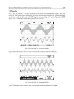
helps to achieve this position. The tips of the open, distal
legs of the device, which are closest to the septum (toward
the patient’s right) begin to fold or bend partially away
from the catheter/sheath as they touch against the poster-
ior/superior septum (Figure 28.12).
The legs of the proximal, right atrial umbrella are visible
on fluoroscopy, folded within the sheath and still not
pulled back to the right side of the septum. TEE/ICE
demonstrates the relationship of the tips of the extended
legs to the atrial septum better, as well as showing the dist-
ance of these legs and the center of the device to the atrial
defect. With the distal legs extended fully, the lock nut on
the delivery catheter remains tightened on the delivery
rod. While holding the sheath and catheter firmly fixed
CHAPTER 28 Atrial septal defect occlusion
761
together at the hub of the sheath, the combination sheath,
delivery catheter, delivery wire, and attached device,
all together are withdrawn slowly along the posterior–
superior septum toward the atrial defect. The device and
its relationship to the septum are observed very carefully
with both fluoroscopy and TEE/ICE. As the device is
withdrawn, the distal legs, which are touching the sep-
tum, begin to bow and/or bend away from the sheath and
often, create a steep angle to the other open legs of the
device. The right atrial disk is visible still folded within
the sheath, which in turn, demonstrates the relationship
of the tips of the legs of the right atrial umbrella to the
right side of the defect (Figure 28.13). The simultaneous
TEE/ICE image clearly demonstrates the open legs, their
proximity to the atrial septum, and their relationship to
the atrial septal opening. Often the device still appears
almost perpendicular to the surface of the atrial septum.
The entire system is withdrawn slowly until a tip of one
leg of the left atrial umbrella, which already is against
the septum, approaches within 4–5mm of the edge of the
atrial defect as seen on TEE/ICE. The TEE/ICE shows the
angle of the device against the septum and how far away
the remaining left atrial legs are from the septum.
TEE/ICE will show the atrial septal tissues and may help
to determine whether the tips of the proximal device, still
folded within the sheath, have reached the right side of the
septum (see Figure 28.13). A small, hand injected, angio-
cardiogram is performed through the additional angio-
graphic catheter which is positioned through, and just
on the left atrial side of, the atrial septal defect. The tip
of this additional catheter may be against the proximal
surface of the opened distal umbrella of the device. The
Figure 28.13 More cephalad legs of left atrial umbrella of a CardioSEAL™
device beginning to “bow” as device is withdrawn along septal surface and
more into defect. The position of the legs of the right atrial umbrella, which
are still folded within the sheath but are extending to the right side of the
septum, are visible on fluoroscopy/angiography.
Figure 28.12 Left atrial umbrella of a CardioSEAL™ device opened in the
left atrium. Device is very malaligned with the atrial septum. Folded right
atrial umbrella still within the sheath does not extend to the right side of
the septum.
CHAPTER 28 Atrial septal defect occlusion
762
angiocardiogram confirms whether the tips of the legs of
the proximal umbrella, which are still folded within the
sheath, have reached the right side of the plane of the sep-
tum and verifies the position of the open distal umbrella
against the septum (see Firgure 28.13). If the right sided
umbrella is not quite far enough to the right of the septum
in order to ensure that the right legs will open on the right
of the septum, the sheath/catheter/device, with TEE/ICE
imaging, are withdrawn carefully together and/or rotated
slightly and the angiocardiogram repeated.
Once the tips of the right legs are far enough through
the ASD and positioned so they clearly will open on the
right side of the septum, the angiographic catheter is with-
drawn into the right atrium. The delivery catheter (with
the delivery rod/wire and device) is fixed in place against
the tabletop and/or the patient’s leg and the sheath
alone is withdrawn well off the proximal legs of the device.
This allows the proximal (right atrial) legs to spring open.
Usually the device reorients slightly and aligns better
with the septum when the sheath is well away from the
device (Figure 28.14). With the two “umbrellas” open on
the opposite sides of the septum, the device is in a relat-
ively secure position before its purposeful release. It is
tested with very slight, gentle to-and-fro motion on the
delivery catheter/wire. The device position is checked
by TEE/ICE and a repeat angiocardiogram performed
through the additional venous catheter. If there is a gross
malposition of the device, at this point with the device
still attached, the device still is retrievable, albeit with
some difficulty.
A technique used during the earlier trials and which
remains as an alternative technique for positioning the
CardioSEAL™ or the STARFlex™ device on the septum
and over the defect is to begin the positioning and deploy-
ment of the device with the sheath in or near the left
upper pulmonary veins. With this technique, the tip of the
sheath is withdrawn out of the pulmonary vein and the
distal (left atrial) umbrella is deployed as described above.
The entire system is withdrawn from the mid left atrium
slowly toward the septum and the atrial defect while
observing on TEE/ICE and fluoroscopy. The device is
withdrawn until just the tip of the very first of the open dis-
tal legs approaches and barely touches the septum as seen
on the TEE/ICE. This usually is the most cephalad leg of
the device. Usually, but not reliably, this leg bends slightly
away from the septum on fluoroscopy as it touches it.
At this time, all of the distal (open) legs still should be on
the left atrial side of the septum while the tips of the prox-
imal legs, which still are folded within the sheath, should
be through the defect, and on the right side of the atrial
septum. The correct position can be verified by perform-
ing an angiocardiogram through the additional venous
catheter which was previously positioned through the de-
fect on the left atrial side of the atrial septum and adjacent
to (touching!) the proximal side of the opened distal
umbrella. The TEE/ICE confirms that all of the legs of the
open left atrial umbrella still are on the left side of the sep-
tum. The angiocardiogram demonstrates that the folded
legs of the right atrial umbrella are far enough through the
defect to open on the right atrial side of the septum. When
the correct position of all the legs is confirmed to the satis-
faction of the operator, the second venous catheter is with-
drawn into the right atrium and the right atrial umbrella
of the device deployed by withdrawing the sheath off the
right sided legs of the device while fixing the delivery
catheter/delivery rod/device in place.
Before the right atrial legs are opened and/or when one
or more of the left atrial legs pulls through the defect
and/or the right atrial legs do not appear to extend far
enough through the defect to be able to open on the right
atrial side of the septum, the sheath, catheter and device,
all together, can be re-advanced back into the left atrium.
This can be accomplished only before the right atrial umbrella
Figure 28.14 Both umbrellas of CardioSEAL™ device opened on
septumAdevice still attached to delivery cable.
CHAPTER 28 Atrial septal defect occlusion
763
is deployed. When free in the left atrium and as viewed
on fluoroscopy and TEE/ICE, the combination of sheath/
catheter/device with only the left atrial disk open is rotated
slightly as a “unit” in order to produce a better orientation
of the left atrial disk in relation to the septum, and the
positioning process repeated. If the device pulls through
the defect completely with all of the left legs open but
before any of the right atrial legs are opened, an attempt
can be made at withdrawing the delivery catheter along
with the distal legs of the attached device back into the
sheath and then to re-advance the sheath with the totally
enclosed device back through the defect into the left atrium.
If any one of these steps cannot be performed, the device is
withdrawn through the sheath and out of the body.
Exact positioning on the septum is confirmed by
TEE/ICE before release of the device. Until this step in the
procedure, the device can be withdrawn, at least partially,
back into the delivery sheath and is retrievable with only
moderate difficulty. However, once the device has been
released, the retrieval of a CardioSEAL™ or STARFlex™
device is very difficult. Occasionally, and particularly if
the device embolizes through the right ventricle to the
pulmonary artery, or, even worse into the left ventricle,
catheter retrieval usually is not a reasonable option, even
if potentially possible. In that circumstance, the device
should be retrieved surgically and the defect closed
surgically. Fortunately, even with embolization into a
ventricle, the embolized device usually does not compro-
mise hemodynamic stability so that the surgical retrieval
does not require an emergent, life-saving procedure.
When the correct position in the defect and on the sep-
tum is confirmed with TEE/ICE, the device is ready for
release. When satisfied that all of the legs are on the proper
sides of the septum, the sheath is fixed in place while very
gentle traction is applied to the delivery rod/wire. The
slide-tumbler, attach/release mechanism at the proximal
end of the catheter is activated by raising the lever or
“plate” on the tumbler and pushing the tumbler forward.
The fixed device often turns and/or springs away from
the attaching wire and often “swings” to and fro on the
mobile septum. Usually after release, the device aligns
better with the atrial septum and often the CardioSEAL™
and usually the STARFlex™ devices “self center” very
nicely on the defect. The proper position on the septum is
rechecked with TEE/ICE, observing specifically for the
relationship of all of the legs of both umbrellas to each
other and to their proper side of the septum. TEE/ICE/
Doppler interrogation identifies the integrity of the
closure or any persistent leaks.
The X-ray tube that was used to measure the defect with
the balloon and/or during the deployment of the device is
repositioned to align the device precisely on edge. A select-
ive angiocardiogram is performed with an injection of a
large bolus of contrast into the right atrium. This demon-
strates the right side of the device on the septum very
clearly and, by observing the flow of the contrast through
the left heart during recirculation, the left atrial side of the
device is visualized fairly well. Re-manipulation of the
angio-catheter from the right atrium, to the right ventricle
and into the pulmonary artery is potentially dangerous
and unnecessary and there is a significant risk of dis-
lodging a freshly implanted device by nudging it with an
inadvertent bend and/or twist of the proximal shaft of
the catheter. The “recirculation” image after an injection
into the pulmonary artery is not significantly better for
identifying residual leaks than the recirculation images
from a large bolus injection in the right atrium.
In an effort to lessen the pressure effect of the acute
“trapping” of the shunt volume load in the left heart
following the sudden, successful closure of atrial septal
defects, patients are given 0.25–0.5 mg/kg of furosem-
ide intravenously just before or immediately after the
device is implanted. This dose is repeated in 6–8 hours
in patients with very large defects or “precariously”
implanted devices. The catheters are removed and
hemostasis achieved by pressure over the puncture sites.
Since a “foreign body” has been implanted, these patients
are treated with antibiotic prophylaxis primarily against
Staphylococcus aureus and appropriately for the size of the
patient for 24 hours.
Pecularities of the STARFlex™ ASD Occluder
Because of the need for some type of “centering mechan-
ism” on either the Clamshell™ or CardioSEAL™ ASD
devices, the manufacturer developed the STARFlex™
ASD device to address this short-coming
16
. The
STARFlex™ ASD device actually represents a very min-
imal modification of the CardioSEAL™ device. Except for
the new “centering mechanism”, all of the major features
of the STARFlex™ device are identical to those of the
CardioSEAL™ device. The “centering mechanism” con-
sists of four, very fine, Nitinol™ micro spring wires, which
extend from the tip of a leg on one umbrella to the tip of
the nearest leg on the opposing umbrella. When the
device is opened in the atrial septal defect, the tiny spring
wires create a “sling” from the tip of a leg on one side of
the septum, through the edge of the defect, to the tip of the
nearest leg on the other umbrella on the opposite side of
the septum. These tiny micro spring wires are stretchable
enough to allow the legs to be folded the 180° away from
each other for delivery without “over-stretching” the
micro spring wires. Yet when both umbrellas of the device
are opened in a defect, the four “slings” theoretically are
strong enough to push the tips of each of the legs of the
umbrella toward the center of the device/defect from
all four “quadrants” around the circumference of the ASD
and, in doing so, effectively center the device in the ASD.
CHAPTER 28 Atrial septal defect occlusion
764
With several minor exceptions, the loading and deliv-
ery of the STARFlex™ devices are identical and were dis-
cussed with the previously described technique for the
delivery of the CardioSEAL™ and STARFlex™ devices.
When the STARFlex™ devices are opened and inspected,
the fine Nitinol™ micro spring wires are inspected in
particular to be sure that they are not damaged (over-
stretched and/or “unwound”) and that they are not
entangled with the legs, hinges, fabric or sutures on the
devices. Keeping these tiny wires free and untangled
is particularly important during the loading of the
STARFlex™ device into the Quick-loader™ or the modi-
fied loader. When one of the tiny micro wires becomes
tangled, the micro spring wire can be released easily by
relaxing any tension on the device and then gently lifting
the trapped wire away from its abnormal attachment with
the tip of a small forceps.
The second, and only other major difference between
the STARFlex™ and the CardioSEAL™ device occurs
during the extrusion of the distal legs of the device during
the delivery procedure. As the distal legs are opened, the
central hinge mechanism of the device is kept well within
the tip of the sheath so that the most proximal segments
of the legs of the device rest against the tip of the sheath,
and the fine centering springs wires, which now extend
from the tips of the distal legs back to the tip of the sheath,
do not flex or bend the open legs unduly back toward the
sheath (Figure 28.15). If the central hinge mechanism
extends beyond the tip of the sheath, tension is placed on
the tips of the left atrial legs, which curves the tips of the
legs of the open umbrella almost perpendicularly toward
the septum and reduces the effective diameter of the
device as it is being pulled back toward the septum
(Figure 28.16). The extreme of this tension on the legs
causes the left atrial umbrella to assume a configuration
that resembles more the shape of a parachute or “jellyfish”
umbrella (Figure 28.17). This configuration prohibits
proper seating over the atrial septal defect. If this
configuration occurs, the sheath is advanced very slightly
forward over the delivery catheter/wire in order to with-
draw the central hinge mechanism of the device back
within the tip of the sheath and press the tip of the
sheath against the most central segment of the distal legsa
hopefully pushing the open legs to a more perpendicular
position.
When the left atrial disk is deployed properly, the micro
springs extend straight from the tip of the sheath to the
straight legs of the left atrial disk. As the entire system is
withdrawn, the micro springs are stretched across the
edges of four quadrants of the atrial defect and, in the pro-
cess, tend to center the device on the septum during deliv-
ery (Figure 28.18). The micro spring wires are not very
sturdy and cannot be relied on to center the device against
a strong lateral force of the remainder of the delivery sys-
tem. Otherwise the withdrawal of the device against the
septum and the device deployment are the same as for the
CardioSEAL™ device.
Excellent safety and efficacy were demonstrated in clin-
ical trials in Europe and the STARFlex™ achieved CE
mark approval. Since then the STARFlex™ device has had
successful clinical use in Europe
18
. In the United States,
the STARFlex™ was introduced into FDA monitored
clinical trials in late 1998. The total number of patients
required in order to provide statistical data for the US
FDA trial was completed by early 2000. The clinical trial
was stopped while the follow-up data were being accu-
mulated and reviewed by the FDA. While the data were in
review, a “supplemental use” of the device briefly was
available to the original investigators for use to treat
Figure 28.15 Left atrial legs of STARFlex™ device opened properly in left
atrium with centering micro springs stretched taut and left atrial legs still
extended straight.
CHAPTER 28 Atrial septal defect occlusion
765
appropriate patients on a modified protocol, however,
this essentially has disappeared in the United States.
The immediate and total occlusion of the ASD is
improved with the STARFlex™ device compared to the
CardioSEAL™ device, however there still were at least
5–10% with residual leaks after successful implant. In
addition, after apparent, totally successful implants and
total occlusions of the defect with the 40 mm STARFlex™
device, several of these large STARFlex™ devices embol-
ized away from the ASD within several hours after
implant. This occurred only with the 40 mm devices.
Further investigation indicated that the finer MP-35N
metal of the longer legs of the 40 mm devices probably
was not strong enough to support the device against the
sudden significant pressure difference between the two
atria, which occurs when the shunt is stopped suddenly
following occlusion of the larger defects. The 40 mm
device eventually was abandoned for use for closing the
large isolated ASD.
As a consequence of the problem with the 40 mm
STARFlex™ device, two new devices of the same mater-
ials were developed and tested in animals. These ASD
occlusion devices each had six arms on each umbrella and
the umbrellas were 38 and 43 mm in diameter. The extra
arms on each side created a sturdier device and the six
arms created a hexagonal configuration, which covered a
much larger area for a given device diameter. In spite of
the extra, and longer arms and the increased fabric, these
new devices still were delivered through 11- and 12-
French sheaths. Unfortunately, these larger, six-armed
STARFlex™ devices still are not available even in inves-
tigative trials for the occlusion of the significantly larger
ASD or any other defects in the United States.
Figure 28.16 Sheath withdrawn too early off right atrial legs and too far
within left atrium, causing the micro springs to create central and rightward
tension on the tips of the left atrial legs.
Figure 28.17 Extreme malformation of the left atrial disk of STARFlex™
device when the whole device is extended too far out of sheath. The left
atrial legs are folded back even further into a “jellyfish” umbrella
configuration.
CHAPTER 28 Atrial septal defect occlusion
766
Eustachian valve and the delivery of the
CardioSEAL™ and STARFlex™ ASD devices
The presence of a large and redundant Eustachian valve
creates a significant problem during the delivery of the
CardioSEAL™ and STARFlex™ devices. Because of the
“pull” toward the inferior vena cava on the delivery
catheter and when the delivery sheath is withdrawn off
the right atrial legs of these “true umbrella” devices dur-
ing the delivery of the device, the initial opening of the
“spring mounted” right atrial legs begins far out into the
body of the right atrium and/or actually toward (into!)
the inferior vena cava. When there is a large flap of
Eustachian valve tissue extending close to the ASD and,
as the right-sided legs spring open, the legs very easily
and very likely catch on the Eustachian valve tissues. The
larger the device (the longer the legs) and/or the larger/
longer the Eustachian valve, the greater is the chance
of this occurring. The legs catching on the Eustachian
valve tissue prevents the right atrial legs from opening
completely and results in the trapped legs protruding out
into the cavity of the right atrium. The tethered portion
of the Eustachian valve along with the attached right
atrial umbrella also potentially and selectively “funnels”
desaturated inferior vena caval blood selectively under
the device toward the left atrium.
This potential problem should be recognized easily and
is preventable. In every case, the right atrium and the area
of the atrial septal defect are scrutinized very carefully by
TEE or ICE for the presence of redundant and/or long
Eustachian valve tissue. The large Eustachian valve read-
ily is recognized on the TEE/ICE image as a thin structure,
which flaps freely and consistently in the right atrium
close to, or even in front of, the atrial septal defect. The
Eustachian valve can have thicker tissues and/or can have
an attachment to the septum giving it the appearance
of a “septum” across the right atrium. When excessive
Eustachian tissue is recognized, a 6-French, EPT DX,
Unidirectional, Steerable, Diagnostic Electrophysiology
(EP) “mapping” catheter (Boston Scientific, Natick, MA)
with a two-dimensional, controllable, deflecting curve at
the tip is introduced through an additional venous sheath.
These deflectable EP catheters allow the formation of a
180° curve, or loop, at the tip of the catheter, which once
formed, can be locked in position. The straight deflector
catheter is advanced from the inferior vena cava into the
right atrium and advanced cephalad beyond the free end
of the Eustachian valve. While observing on fluoroscopy
as well as TEE or ICE, a tight curve is formed on the
“deflector catheter” in order to trap the free end of
the Eustachian valve. Once the “flapping tissue” of the
Eustachian valve is trapped, the “flapping” structures
on the echo image disappear and/or are moved by the
deflector catheter
19
. The deflected curve on the catheter is
locked in position, and the curved catheter with the
trapped Eustachian valve is withdrawn toward the infe-
rior vena cava and away from the atrial septal defect. It
usually takes only a few attempts to trap the Eustachian
tissues with the curved deflector catheter. The Eustachian
valve is held in this position away from the septum while
the device is delivered to the atrial septal defect. Once the
device is in place, the curve on the EP catheter is relaxed
which, in turn, releases the Eustachian valve tissue. The
released Eustachian valve tissues then may flap against
the right side of the device which, however, causes no
problems.
When the Eustachian valve is not recognized or cannot
be “retracted” satisfactorily with the deflector catheter
and does become caught on the device, the Eustachian
tissues still can be freed from the device using a sizing
balloon and/or a large angioplasty balloon. An end-
hole catheter is advanced from the inferior vena cava into
the right atrium, manipulated very carefully and very
Figure 28.18 Sheath withdrawn properly off STARFlex™ device, allowing
the micro springs to help “center” the device in the atrial defect and yet not
folding the legs too tightly backward on themselves.
CHAPTER 28 Atrial septal defect occlusion
767
close to the device, then past the device and from there,
into the superior vena cava. The spatial relationship of
the catheter to the device and the Eustachian tissue is
determined with fluoroscopy and TEE or ICE. When the
catheter has passed between the trapped leg(s) of the
device and the Eustachian tissue, the catheter is replaced
with an exchange length, spring guide wire. A large dia-
meter sizing or angioplasty balloon is advanced over the
wire and maneuvered very gingerly to a position adjacent
to the device. A single inflation of the balloon usually is
sufficient to separate and release the trapped leg(s) from
the tissues. If not, the deflated balloon is moved along
the wire and/or the wire is repositioned all together and the
inflation repeated. There have been occasions where the
legs of the device became trapped on the Eustachian valve
but the legs were left trapped with the legs (and presum-
ably, the umbrella) extending out into the body of the
right atrium with no reported adverse effects. However, it
appears advisable to avoid the entrapment by prevention
or to accomplish the separation of the legs from the
Eustachian tissue during the same procedure.
Retrieval of the cardioSEAL™ and STARFlex™
devices
With the CardioSEAL™ and the STARFlex™ ASD
devices, like all catheter-delivered devices, there are
occasional malpositioned devices and even displaced and
embolized devices. Contingencies are available for their
retrieval. The ease (or difficulty) of retrieval depends a
great deal upon at what particular stage of the delivery/
implant the device becomes malpositioned. With the
CardioSEAL™ and the STARFlex™ devices this is particu-
larly true.
For all of the 28 mm and larger devices and before
the long delivery sheath is introduced into the vein for
the routine delivery of a CardioSEAL™ or STARFlex™
device, a long sheath/dilator is passed through a short,
stiff 14+-French “rescue” or “recovery” sheath. Either a
short, stiff, 14-French sheath or a short, thin-walled, 14-
French, metal cannula with a hub makes an ideal “rescue”
or “recovery” sheath! The short 14+-French, “rescue”
sheath is withdrawn over the sheath, back to the hub of
the long sheath and remains there throughout the stand-
ard procedure. This short “recovery” sheath serves as a
supplemental and external support sheath for the with-
drawal out of the vessel and through the skin for a device
that has been opened but still is held by the delivery wire
and/or grasped by a retrieval catheter. For the standard
CardioSEAL™ or STARFlex™ delivery, the long delivery
sheath is introduced into the vessel similarly to any other
device delivery, but with the short “rescue” sheath, which
is positioned over it, remaining back at the hub of the long
sheath. The short recovery sheath is not introduced into
the skin or the vessel unless a retrieval of an opened
device is necessary.
When only the distal legs of the CardioSEAL™ or
STARFlex™ devices are deployed and the device still is
attached to the delivery catheter/wire, the entire device
can be withdrawn most, if not all of, the way back into the
delivery sheath by pulling the delivery catheter/wire back
while fixing the sheath against the device. The smaller
devices usually can be withdrawn completely into the
sheath. With the larger devices, the very distal segment of
the arms (beyond the last “wrist” joint) often fold out and
hang over the outside of the end of the sheath and further
attempts at withdrawing the device only buckles and/or
accordions the long sheath. In order to remove the par-
tially withdrawn device from the vessel, first the skin and
subcutaneous tissues around the long delivery sheath are
infiltrated liberally with local anesthesia and the skin inci-
sion is extended slightly around the long sheath. The short
14-French “recovery” sheath is introduced into the vein
over the 11-French long sheath with a smooth, fast, rotat-
ing motion. The long sheath with the legs of the umbrella
still hanging out of the distal end of the sheath is with-
drawn into the inferior vena cava until the tip of the long
sheath approximates the tip of the short “rescue” sheath.
The very flexible, exposed parts of the legs hanging out of
the tip of the delivery sheath tend to become folded away
from the tip of the sheath as it is being withdrawn through
the more peripheral vein even before they reach the short
recovery sheath. When the legs are folded away from the
tip of the sheath, the flexible legs do not catch on, or dam-
age venous structures as the long sheath is withdrawn.
Pulling the sheath, delivery catheter and attached device
against the stiff, short “recovery” sheath, very effectively
completes the folding, and allows the still extended legs to
be pulled into the short sheath and out of the body.
When both proximal and distal umbrellas have been
deployed, but the device still is attached to the delivery
wire/catheter, the devices usually still can be withdrawn
partially into the tip of the long sheath. This maneuver,
of course, everts the proximal umbrella 180° away from
its original position/direction in the sheath. As a con-
sequence, it requires considerably more force to withdraw
even part of the device into the sheath. The delivery
catheter is re-advanced over the delivery cable and against
the pin connector of the device to add support to the shaft
of the long sheath. The combination of catheter, delivery
wire and deployed device are withdrawn against and, as
much as possible, into the long sheath, which, of course, in
doing so, destroys the device. When applying this force,
the full length of the long sheath must be observed inter-
mittently for distortion and damage to the long sheath.
The force required to pull the device into the long sheath
may be greater than the wall strength of the sheath, and
result in the long sheath “accordioning” on itself. If the
CHAPTER 28 Atrial septal defect occlusion
768
device does not pull into the long sheath, the short 14-
French “recovery” sheath is introduced into the vein as
described above. The long sheath with the partially col-
lapsed legs extending out of the tip of the sheath is with-
drawn carefully down the inferior vena cava and iliac vein
to the tip of the short sheath. As the partially exposed legs
of the device are withdrawn through the veins, they tend
to fold and taper away from the tip of the sheath and away
from the direction of withdrawal. The exposed, tapering
and flexible legs do not create much resistance to the with-
drawal and do not traumatize the vessel wall signifi-
cantly. Once pulled against the short sheath, the entire
combination usually folds into and can be pulled com-
pletely into the short recovery sheath.
When retrieving a device after both umbrellas have
been deployed, all of the device legs may not withdraw
completely into a standard “plastic”, 14-French recovery
sheath and begin to “accordion” the short recovery sheath
as well. Usually, even in this circumstance, enough of the
device is covered within the short sheath to allow the com-
bination to be withdrawn out of the vessel with minimal
extra force and minimal vessel/subcutaneous tissue trauma.
If the device cannot be withdrawn into the larger dia-
meter recovery sheath or out of the skin and/or the device
becomes free from the delivery catheter in the iliac area
(either released purposefully or if the device breaks loose),
the “free” device usually will not “embolize” centrally
from a more peripheral vein. The angles created by the
exposed legs folding away from the femoral area as
the device is withdrawn into the iliac vein also result in
the legs flaring out toward the central circulation and
heart. This angle of the legs fortuitously serves to fix the
device very securely in the peripheral venous location and
prevents the device from “floating” back to the heart even
when released (purposefully or accidentally).
In the event that the device does become free, the deliv-
ery catheter is withdrawn through and out of the delivery
sheath as well as the larger diameter short “recovery”
sheath. A relatively stiff exchange length guide wire is
introduced through the delivery sheath and advanced
adjacent to and past the errant device. Once this wire is in
place, the original delivery and the “recovery” sheaths are
withdrawn and replaced with a significantly larger diamet-
er long sheath/dilator (14–16-French). After the new large
sheath is introduced and its dilator is withdrawn, the
dilator then is modified specifically to help support the
long sheath during the subsequent recovery of the device.
The entire taper at the tip of the large dilator, which was
part of the large sheath/dilator set, is excised but excised
only enough so that it does not become shorter than the
long sheath. This produces a dilator with a squared off
tip and with the much larger lumen of the shaft of the dila-
tor exposed. The “excised” dilator is reintroduced over
the wire and back into the large, long sheath. The tip of the
modified dilator is advanced to just within the tip of the
sheath. Together, the sheath and the enclosed modified
dilator create a very thick and strong walled “retrieval
sheath”. A retrieval device (basket or snare) is introduced
through this combination of now “open-ended” dilator
and the large sheath. The device is captured with the
appropriate retrieval device and withdrawn forcefully
into the new much larger and stronger sheath/dilator
combination. As the captured device is withdrawn into
the sheath, the dilator can be withdrawn into the sheath
along with the device.
When a CardioSEAL™ or STARFlex™ occlusion device
is displaced and/or embolizes remotely after it is released
from the delivery catheter, then the retrieval falls into the
category of a very complex “foreign body” recovery. The
general principles for the retrieval of free-floating foreign
bodies are covered in detail in Chapter 12. How, and
whether, the errant device can be retrieved depends upon
both the location where the device stops and what
retrieval equipment is available. Fortunately, when these
devices do embolize, they usually pass completely
through the respective atrio-ventricular valves and/or the
right or left ventricle and move on through the ventricle to
the respective great artery without producing any hemo-
dynamic compromise. In these positions the device usu-
ally is very stable and represents no immediate danger to
the organ(s) adjacent to where it sits and to the patient
in general. This allows the organization of a relatively
“elective” retrieval!
When a CardioSEAL™ or STARFlex™ device
embolizes to the pulmonary artery, the major immediate
decision is whether even to attempt the retrieval in the
catheterization laboratory or to send the patient directly
for a surgical retrieval and closure of their defect. When
either a CardioSEAL™ or a STARFlex™ ASD device is to
be retrieved from the pulmonary artery by a transcatheter
procedure, it must be withdrawn through the ventricle
through a very large, long retrieval sheath, which must be
positioned in the main or even the involved branch
pulmonary artery before grasping the errant device.
A partially collapsed and exposed CardioSEAL™ or
STARFlex™ umbrella never should be withdrawn into
and/or through a ventricle with even a small part of the
device exposed outside of the sheath! The device abso-
lutely must be withdrawn completely into the sheath before
any attempt is made to withdraw it through the right ven-
tricle. When even a part of a single leg of one of these
devices extends out of the end of the sheath, it almost
guarantees that the device will become tangled in the tri-
cuspid valve apparatus. A device tangled in a ventricle
and, at the same time, firmly attached to a retrieval device
and partially within a sheath usually cannot be released
from the retrieval device nor pulled out of the ventricle
without destroying the atrioventricular valve! When a
CHAPTER 28 Atrial septal defect occlusion
769
device that is irreversibly attached to a retrieval catheter
becomes trapped in an atrioventricular valve, the other-
wise elective, controlled thoracotomy retrieval of the
errant device suddenly has been converted into an acute,
open-heart surgical emergency!
If the decision is made to attempt catheter retrieval, and
once a very large, long sheath has been positioned in the
pulmonary artery, a basket retrieval device probably has
the best chance of both grabbing and partially collapsing a
large umbrella enough to withdraw it into a very large
sheath. Although the device can be captured relatively
easily with the basket retrieval device, the downside of
this device in this situation is that, once captured, if the
basket with the device cannot be drawn completely into
the sheath, the device often cannot be released from the
basket! This leaves the patient with the umbrella in the
pulmonary artery, but now with the umbrella “perman-
ently” attached to the retrieval catheter passing through
the entire right heart and extending out of the bodya
again creating a much more urgent and complex surgical
situation.
A retrieval snare represents an alternative retrieval
device and technique that may be preferable for the
retrieval of an ASD device from the pulmonary artery.
This still requires that the device be withdrawn com-
pletely into the sheath before it is withdrawn through
the pulmonary artery. By grasping a single leg or several
adjacent legs of the device, the crumpled umbrella is
“elongated” as it is pulled out of the tissues. This elonga-
tion of the umbrella may facilitate withdrawing the
umbrella into a very large diameter, reinforced, long sheath.
If the device in the pulmonary artery cannot be with-
drawn into the sheath completely, it usually can be released
from the snare more reliably and, in turn, the catheter
retrieval abandoned more easily and safely.
In the majority of cases, when a large CardioSEAL™ or
STARFlex™ device embolizes into and/or through a ven-
tricle, surgical retrieval is recommended. This makes the
positioning and eventual release of these devices for ASD
occlusions even more critical.
Helex™ ASD device
A more recent addition in the United States to the arma-
mentarium for the closure of the atrial septal defect is the
Helex™ device (W. L. Gore & Associates, Flagstaff, AZ).
This is an entirely new concept with new design features
to overcome some of the shortcomings of the other
devices
20
. The deployed device is basically round. This
shape conforms more to the shape of the usual ASD and to
the shape of the atrial septum. It has no sharp edges and
a very low profile after implant. The Helex™ device is
delivered through a 9-French delivery “catheter” without
the use of an additional long sheath and it is totally
retrievable even after full deployment of the device and
even after its “release” onto the septum from the “rigid”
portion of the delivery catheter.
The Helex™ ASD device is a long strip or “curtain”
of expanded polytetrafluoroethylene (ePTFE) fabric
(W. L. Gore & Associates, Flagstaff, AZ). The “frame” of
the device is a long Nitinol™ memory wire, which passes
through a thin tubular fold along one edge of the long
ePTFE “curtain”. The Nitinol™ wire has an attachment
loop and an eyelet at one end, a dense “central eyelet” at
its center and a third “eyelet” at the distal end of the long
wire. When in its “relaxed state” at body temperature, the
Nitinol™ wire forms a very flat spiral or “helix”, the outer
circumferences of which forms two round circular disks
at each end of the “helix”. The “circular disks” are posi-
tioned on each side of the septum and connected through
the atrial defect by the remainder of the spiral of the
Nitinol™ wire and covering ePTFE material. The circular
curtain of ePTFE fabric attached to this wire frame forms
the two “end” disks. The continuous “curtain”, when
deployed over, and through, an atrial defect, covers the
opening of the ASD with a “disk” on each side of the open-
ing while the material of the “curtain” passing through
the defect, adds additional occlusive material. The center
of the “helix”, along with the attached fabric, which runs
through the defect between the two outer disks, acts as a
partial centering mechanism.
The Helex™ comes in multiple sizes from 15 to 35 mm
diameters in 5 mm increments. It is recommended that
a ratio of device diameter to defect diameter of 1.7:1,
or, preferably, 2:1 be used in choosing the size of the
Helex™ device to be used. The Helex™ device comes
from the manufacturer in its “relaxed”, opened, circular,
“helix” configuration and attached to the delivery system.
The delivery system includes an outer, 9-French delivery
catheter that has a ~90° curve at its distal end. This curve
facilitates passage of the catheter from the right to the left
atrium and produces a better alignment of the device
against the septum during the extrusion of the device.
Within the delivery catheter there is an inner control
catheter, which, in turn, has a central “mandril”, both of
which pass completely through the delivery catheter.
There also is a nylon retrieval cord which passes from the
outside of the proximal end of the control catheter,
through the entire length of the control catheter adjacent
to the mandrel to the distal end of the control catheter,
through the proximal eye on the device and then back to
connect to the distal end of the shaft of the control catheter.
The diagnostic “catheterization” procedure for the
atrial septal defect is the same as for other ASD occlusion
devices. General anesthesia is used primarily because of
the concomitant use of TEE for the implant. As with the
other ASD occlusion devices, intracardiac echo (ICE)
during the delivery and implant may obviate the need
CHAPTER 28 Atrial septal defect occlusion
770
for TEE and, in turn, general anesthesia. An arterial
monitoring line and two venous catheters are used. The
right heart catheterization is performed to quantitate the
ASD and rule out associated defects. An angiographic
“marker” catheter is introduced from the left groin and an
angiocardiogram is performed with an injection into the
right upper pulmonary vein or in a right pulmonary
artery, with one X-ray tube positioned in a shallow
LAO–Cranial view in an attempt to cut the septum
on edge. “Non-stretched” atrial defects are sized with
a NuMED™ “static” sizing balloon (NuMED Inc.,
Hopkinton, NY) introduced through the right groin
similarly to the sizing described previously for the
CardioSEAL/STARFlex™ devices. The atrial defect size is
measured radiographically and by TEE or ICE, while the
sizing balloon is inflated in the defect.
The Helex™ device is delivered from the manufacturer
attached to the delivery system in the “deployed” state
with the circular Helex™ extending just beyond the tip of
the delivery catheter. The Helex™ must be loaded into the
delivery system before use. The delivery system is flushed
through a Tuohy™ valved/side port attached at the prox-
imal end of the delivery catheter and then placed on a con-
tinuous flush during the loading of the device. With the
device placed in a bowl of flush solution and held com-
pletely “under water”, the mandrel is advanced out of the
delivery catheter in small, 5–7 mm increments. As the
mandrel is advanced in this manner the most proximal
part of the circular Helex™ straightens away from the tip
of the catheter while the fold in the “curtain” covers the
mandrel. As each 1–2 cm are straightened, the inner con-
trol catheter along with the mandrel and the straightened
portion of the device are withdrawn into the delivery
catheter until the still curved part of the device again
touches the end of the delivery catheter. Each time the
device is straightened and withdrawn back into the deliv-
ery catheter, entrapped air bubbles are squeezed out of the
fabric and flushed out of the system by the continuous
flush. Once the bubbles are cleared, the mandrel is adv-
anced again, straightening an additional segment of the
device and the straightened segment is withdrawn into
the catheter. The procedure is repeated until the entire
device is elongated, “straightened” around the mandrel
and withdrawn completely into the delivery catheter.
Once completely within the delivery catheter and when
the catheter has been flushed thoroughly, the delivery
catheter is introduced through a short, 9-French sheath in
the right femoral vein and advanced through the right
atrium and manipulated into the left atrium. The delivery
catheter with the loaded device within it is advanced
directly through the defect and into the left atrium with-
out the use of an additional long sheath. By eliminating
the need for the long sheath delivery technique many of
the potential sources of air/clot embolization are reduced.
The angiographic catheter from the opposite groin is posi-
tioned in the left atrium at this time.
The position of the delivery catheter in the left atrium is
confirmed on the TEE or ICE image. The deployment of
the Helex™ device begins by advancing both the mandrel
and the inner control catheter together several centimeters
out of the tip of the outer delivery catheter, which is posi-
tioned in the left atrium. The mandrel then is withdrawn
the same distance, allowing the Nitinol™ frame of the
device to bow away from the mandrel and begin to coil.
The inner control catheter and mandrel (and device) again
are advanced 1–2 cm and the mandril withdrawn the
same distance, uncoiling more device. This procedure is
repeated until the centering eye on the wire of the device
(at the center of the Helex™) reaches the tip of the
delivery catheter. This “eye” should be clearly visible on
fluoroscopy.
At this point, the angiographic catheter is withdrawn
until its tip is just within the defect. The delivery catheter
with the half opened device, is withdrawn until the now
deployed left atrial “disk” touches and is pulled very
gently against the septum as seen by fluoroscopy and
TEE/ICE. A small, forceful, hand injected angiocardio-
gram is recorded through the separate angiographic
catheter to confirm the position of the left atrial disk on the
septum. Similarly to the deployment of the other devices,
the left atrial disk usually does not lie exactly flat on the
septum. The angiographic catheter is withdrawn out of
the defect.
At this point, the inner control catheter and mandrel are
held in place while, first, the outer delivery catheter is with-
drawn several centimeters into the right atrium. The man-
drel, alone, then is withdrawn 1–2 cm, which allows the
right atrial “disk” of the device to begin to uncoil away
from the mandrel on the right side of the septum. Again,
by slowly and meticulously advancing the inner control
catheter and mandrel together and then alternately, with-
drawing the mandrel the same distance, the entire right
atrial “disk” is deployed. The distal end of the inner con-
trol catheter is radio-opaque and is seen as it is advanced
toward the deployed disk. All of this time the left atrial
disk is observed on fluoroscopy and TEE/ICE and main-
tained firmly against the left side of the septum. The com-
plete deployment of the right atrial “disk” is recognized
on fluoroscopy when the opaque tip of the inner control
catheter reaches the right atrial disk and the complete
circles of two wire “disks” approximate each other on the
opposite sides of the septum. Simultaneous with this
appearance, the proximal eyelet of the device becomes
positioned at the end of the catheter and closely approx-
imates the other two eyelets. The “locking” wire with the
mandrel within the inner delivery catheter still appears
straight within the mandrel and should be passing through
all three eyelets.
CHAPTER 28 Atrial septal defect occlusion
771
The angiographic catheter is maneuvered adjacent
to the right atrial disk and a repeat angiocardiogram
recorded. If the device does not appear to be in the proper
position, or if there is a residual leak, the device is moved
and repositioned slightly on the septum by rotating the
delivery catheter slightly while it still is attached to the
device. If the device is out of position completely with one
or the other “disk” prolapsing through the defect, or the
device pulls completely through the defect, the device is
withdrawn back into the catheter. This is accomplished by
repeating the exact procedures used when initially loading
the device into the delivery catheter (reversing the device
extrusion procedure). Once the device is back in the deliv-
ery catheter, the delivery catheter is repositioned into the
left atrium and the delivery procedure repeated with the
same device, or the whole system is withdrawn through
the short sheath and the procedure started with a more
appropriate device.
Once the device is in the proper position as seen by
TEE/ICE and/or angiography, preparations are made
to activate the locking mechanism. The outer delivery
catheter is advanced over the inner control catheter until
the tip of the outer catheter is against the center of the right
atrial “disk”. The red cap that holds the retrieval cord at
the proximal end of the control catheter is removed and,
while holding the outer delivery catheter and mandrel in
place, the inner control catheter is withdrawn 1–2 cm and
then re-advanced back against the proximal (right atrial)
device. This maneuver loosens the retrieval cord and pro-
vides a loop of this cord at the distal end of the control
catheter. The red cap is reattached to the control catheter
to secure the proximal end of the retrieval cord outside
of the body.
While recording on biplane angiography and observing
the entire device and delivery catheter very closely, the
inner control catheter is pushed against the proximal eye-
let of the device while the outer delivery catheter (only) is
withdrawn 2–3 cm off the inner control catheter, follow-
ing which the mandrel is withdrawn out of the device.
This often takes a moderate amount of pull on the man-
drel and requires a simultaneous very firm and precise
fixation of both the delivery catheter and the inner control
catheter in order to prevent the device from being pushed
or pulled through the septum while the mandrel is pulled
forcefully during this release. As the mandrel releases, it
“pops” free and pulls back into the catheter and several
centimeters away from the device. At the same time, the
relatively straight inner catheter tends to move forward
and, in turn, has the possibility of displacing the entire
system/device cephalad slightly. The previously short
straight locking wire, which still is within the distal end of
the inner control catheter, now assumes a slight “curve”.
This curve remains on the end of the catheter while the
locking wire still is within the control catheter and as long
as the catheter still is against the device. When satisfied
that the three eyelets still are “in line” and that the now
slightly curved locking wire is passing through all three
eyelets, the inner control catheter is withdrawn just
enough to “uncover” the locking wire. This allows the
locking wire to form a tight loop on the proximal side of
the device and pulls the three eyelets together while also
releasing the device from the delivery system. The device
usually repositions abruptly as the locking loop forms.
This repositioning usually is into an even more secure
position and alignment on the septum. Even after this
“release”, the device still can be moved on the septum and
in turn, repositioned slightly if desired.
The mandrel serves no more function and is removed
completely from the system. The device still is “tethered”
loosely to the delivery catheter by the safety suture pass-
ing through the eyelet at the proximal end of the Nitinol™
“frame” wire of the device. The outer delivery catheter
carefully is advanced back against the device over this
safety suture. Once the catheter is against the device, the
device can be moved slightly on the septum by rotating
the delivery catheter (which turns the curved tip) a small
amount. If the device comes loose from the septum
and/or cannot be placed in a satisfactory position over the
defect, it still is attached by the safety suture and is com-
pletely retrievable as long as the safety suture remains in
place through the proximal eyelet.
Once satisfied that the device is in a secure position
and is occluding the defect sufficiently, the retrieval
cord (safety suture) is removed. If the mandrel was not
removed completely before, it is removed before remov-
ing the retrieval cord. With the outer delivery catheter
loosely against the device, the red locking cap is removed
and the inner control catheter is slowly withdrawn. This
pulls on the end of the retrieval cord that is attached to the
distal end of the catheter and withdraws the other, loose
end through the outer catheter, through the eyelet and
away from the device.
Retrieval of the Helex™ ASD device
After full deployment and release from the delivery
catheter, but before the withdrawal of the inner catheter
and retrieval cord, the long suture running through the
proximal eyelet of the device still attaches the Helex™
device to the inner catheter. If not satisfied with the place-
ment and/or the degree of occlusion by the device and/or
if the Helex™ dislodges from the defect while it is being
observed/manipulated after release from the delivery
catheter, the Helex™ device still can be retrieved using the
retaining suture. The device is withdrawn back into the
delivery catheter by traction placed together on the suture
and the inner control catheter. Traction on the suture and
the inner control catheter pulls the most proximal eyelet
CHAPTER 28 Atrial septal defect occlusion
772
at the very proximal end of the spiral device back into
the delivery catheter, and with some effort the entire
device usually can be “uncoiled” and withdrawn into the
catheter. As the device is pulled into the delivery catheter
it uncoils into its “loaded” straight configuration. As it is
uncoiling, the device appears to “snap apart” approxi-
mately every centimeter as it uncoils. Even if the device
does not withdraw completely into the delivery catheter,
it is straightened as it is withdrawn into the femoral vein
with the catheter and it can be withdrawn along with,
but outside of, the catheter through the short venous
introductory sheath.
Even after the retrieval cord is withdrawn, the Helex™
still can be retrieved. The original delivery catheter is
replaced with a larger diameter (11-French or larger) long
sheath for the retrieval. If the device is still positioned
on the septum with the proximal eyelet facing the right
atrium, a snare retrieval catheter is used to grasp the
device, preferably around the eyelet. If the eyelet is
grasped, the device is “uncoiled” exactly as when pulling
on the retrieval cord. If an end or eyelet cannot be grasped,
the Nitinol™ frame is grasped anywhere along its circum-
ference with a bioptome or grabber retrieval device. When
a loose “end” of the device is grasped, the device is with-
drawn similarly to using the retrieval cord. When any
other area of the Nitinol™ “frame” is grasped and pulled
forcefully, the “coiled” configuration of the device begins
to unravel and frequently it “unlocks” the device as it
straightens. Even when it cannot be uncoiled, the flexible
wire frame of the Helex™ can be bent and pulled com-
pletely into a very large diameter sheath. With the ability
to pull an errant device completely into the retrieval
sheath, it is reasonably safe to retrieve a Helex™ device
from a pulmonary artery when the large sheath can be
positioned through the right ventricle and into the pul-
monary artery before the device is grasped.
Sideris ASD Button Occluder
The Sideris ASD “Button” Device™ (Pediatric Cardiology
Custom Medical Devices, Athens, Greece) is yet another
ASD occlusion device. The Button™ device has been in
multiple international trials throughout the world and has
had extensive clinical use for over a decade outside of the
United States. The Button™ ASD occluder currently has
CE approval for clinical use in Europe
21
. The ASD Button
Device™ has had at least one US FDA clinical pilot trial
but, like most ASD devices at the present time, is available
for ASD closure in the US only in investigational trials.
This device began as a single square of 1/16″ thick
polyurethane foam sewn onto an “X” shaped skeleton or
frame of two, equal length, crossed pieces of stiff, 0.018″
teflon-coated, spring guide wire
22
. The length of the wires
of the frame determines the size of the device. Each of the
wires of the frame has a 2 mm floppy portion at each end.
The two wires of the frame are attached at their centers to
make the “crossed” frame of the left atrial “occluder disk”
or umbrella with the foam disk sewn to the frame. The left
atrial disk or “occluder” is held against the septum by a
separate “counter occluder” piece. The counter occluder
originally was a single bar of relatively stiff spring guide
wire but now is a narrow rhomboid of similar wire, which
is covered with polyurethane. The counter occluder is
held against the occluder umbrella by a unique connect-
ing or “buttoning” mechanism.
With the initial “Button” device, there was a suture knot
or “spring button” on one small, 2 mm loop of suture
attached to the center of the proximal (right atrial) side
of the left atrial “occluder disk”. The fourth generation
device has two suture knots situated between three small
suture loops in line at the center of the proximal side of
the occluder. The suture knots form the “buttons” for the
attachment of the device. The counter occluder has a small
piece of latex, which forms a plug attached to the center of
the wire bar of the counter occluder. The latex plug on the
counter occluder has a hole in it, which forms the “button
hole” for the “buttons” on the occluder. A “through-and-
through” “control suture” passes through the latex plug,
through a length of a fine hollow “loading wire”, through
the most proximal suture loop on the “occluder”, and then
passes back through the “loading wire” and the latex plug
at the proximal end of the hollow “loading” wire. The
latex plug on the counter occluder along with the counter
occluder is advanced over the control suture and loading
wire with an end-hole, “pusher” catheter. When the
counter occluder, which is advancing over the loading
wire, reaches the defect and the occluding umbrella, the
latex plug is pushed forcefully with the pusher catheter
and over the two knots or “buttons” on the occluder to
“button” the counter occluder to the occluder.
The left atrial occluder, the attaching mechanism and
the counter occluder all have been modified over the past
decade, now through four or five “generations” of the
device
23
. The buttons were made radio-opaque on the
second-generation device. The attaching mechanism on
the occluder now has two radio-opaque knots on triple
suture loops. The knots or “buttons” are between each of
the small loops and each are 4 mm apart. The counter
occluder now is a narrow rhomboid of two strands of the
teflon-coated wire and is covered with a rhomboid-
shaped piece of polyurethane foam. The counter occluder
now is pushed over both “buttons” for a more secure
attachment. The first four generations of Button™ ASD
devices had no centering mechanism and required a 2:1,
device to defect diameter ratio. The fourth generation
ASD Button™ device is available in 25–60 mm diameters
in five millimeter increments (only up to 55 mm are avail-
able in the US). The fourth generation device now also is
CHAPTER 28 Atrial septal defect occlusion
773
delivered with an additional, over the wire delivery tech-
nique. There are several recent additional modifications of
what is still the fourth generation device. The most recent
modification has an additional large loop of spring wire
attached to the center of the proximal side of the occluder
to facilitate centering, and has a round disk of poly-
urethane on the original “X” frame. This most recent
modification is called the “COD™” (Centering On
Demand™) Button device.
As with most of the other ASD devices, the Button™
ASD device is delivered to the ASD through a long sheath
using fluoroscopic and TEE or ICE guidance. A long
sheath with a back-bleed valve/flush port is used and the
same precautions for clearing the sheath of air and clots
are used as are used with the other devices. The earlier
generations of this device were very flexible and com-
pressible. Because of this and the compressibility of the
polyurethane foam, they could be folded to a very small
diameter and, in turn, delivered through a much smaller
sheath than any of the other tested ASD occlusion devices
at the time. The newer generation devices still have square
umbrellas of polyurethane, but with a larger or thicker
counter occluder and with the additional centering wires,
they are not as compressible. Depending upon the size
of the occluder, an 8–11-French long delivery sheath is
now required for their delivery.
The exact size of the ASD now is measured by a
static, non-stretched, balloon sizing technique, which is
described previously and in detail under the description
of the CardioSEAL/STARFlex™ technique. After the
defect is sized accurately with the balloon, the sizing
balloon is replaced with the long delivery sheath/dilator
over the exchange wire, which is positioned in the left
upper pulmonary vein. The dilator and then the wire
are removed cautiously and separately, observing pre-
cautions to prevent the introduction of any air. When
“the over the wire” technique is to be used, the floppy
tip of an exchange length 0.021″ Amplatz™ wire is
advanced through the sheath/dilator and positioned
into a left upper pulmonary vein before the dilator is
removed. The wire remains in this position through the
sheath during the delivery and implant of the occluder
device.
The occluder (left atrial disk) and the counter occluder
are delivered separately, however, both components are
delivered through the same long sheath. A very long loop
of 0.008″ nylon “control suture” passes from proximally to
distally through a long, metal, hollow “loading wire”
which eventually extends through the entire length of the
sheath. The control suture then passes through the most
proximal, small loop or eye at the end of the “button”
sutures (at the center of the right side of the “occluder”)
and then back through and out of the proximal end of the
long, hollow “loading wire”. The attaching suture “eye” is
proximal on, and in line with, the buttons at the center of
the left sided occluder umbrella.
The corners of the occluder are folded manually toward
and into the hub of the long sheath or into a short segment
of sheath of the same size, which is used as a loader in
order to introduce the device through a back-bleed valve.
The entire device is introduced into the proximal hub
of the long sheath. If the “over the wire” technique is used,
the proximal end of the wire, the distal end of which is
positioned in the pulmonary vein, is passed through the
fabric at the center of the “occluder” before the “occluder”
is folded into the loader/delivery sheath. The wire passes
through a small hole pierced immediately adjacent to the
central, cross pieces of the frame of the occluder. An end-
hole “pusher” catheter is advanced over the long, “hollow
wire” which contains the control suture attached to the
“button loop”. The pusher catheter is advanced over the
“hollow wire”, the long suture and the extra “guide wire”
(if used) until the tip of the pusher catheter is up against
the center of the folded “occluder”. The pusher catheter,
which now contains the “hollow wire” with the control
suture, is advanced into the delivery sheath behind the
folded “occluder”. It also is advanced over the long
exchange Amplatz™ wire (Cook Inc., Bloomington, IN), if
the “over the wire” delivery is used. The folded occluder
is pushed through the long sheath with the pusher
catheter until the occluder is pushed completely out of the
sheath and into the left atrium, where it opens and “hangs”
loosely. The control suture within the hollow wire is with-
drawn firmly against the tip of the delivery sheath, which,
in turn, pulls the open left atrial “occluder” against the
end of the sheath. The long wire, which is fixed in a left
upper pulmonary vein as part of the “over the wire” addi-
tion to the delivery system, keeps the occluder more or
less in line with the septum and away from the mitral
valve after it is pushed out of the long sheath and free into
the left atrium and before the occluder is pulled back
against the atrial septum.
When pulled back against the tip of the sheath with the
control suture, the occluder (left atrial disk) aligns perpen-
dicular to the end of the sheath. The sheath, with the
occluder against it, is pulled back against the septum and,
in doing so, the device should cover the atrial defect.
When satisfied with the position by TEE/ICE and/or an
angiocardiogram performed through a separate catheter,
the pusher catheter is withdrawn from the long delivery
sheath while tension is maintained continually on the con-
trol suture (and thus the “occluder”) against the septum.
Once the pusher catheter has been removed, the central
latex plug on the counter occluder is loaded over the hollow
“loading wire” with the contained control suture, but
adjacent to the long Amplatz™ guide wire (if the over the
wire technique is being used). The counter occluder is
angled lengthwise and parallel to the control suture/