Introduction to GPS The Global Positioning System - Part 5 ppt
Bạn đang xem bản rút gọn của tài liệu. Xem và tải ngay bản đầy đủ của tài liệu tại đây (198.41 KB, 15 trang )
5
GPS Positioning Modes
Positioning with GPS can be performed by either of two ways: point posi-
tioning or relative positioning. GPS point positioning employs one GPS
receiver that measures the code pseudoranges to determine the users posi-
tion instantaneously, as long as four or more satellites are visible at the
receiver. The expected horizontal positioning accuracy from the civilian
C/A-code receivers has gone down from about 100m (2 drms) when selec-
tive availability was on, to about 22m (2 drms) in the absence of selective
availability [1]. GPS point positioning is used mainly when a relatively
low accuracy is required. This includes recreation applications and low-
accuracy navigation.
GPS relative positioning, however, employs two GPS receivers simul-
taneously tracking the same satellites. If both receivers track at least four
common satellites, a positioning accuracy level of the order of a subcenti-
meter to a few meters can be obtained [2]. Carrier-phase or/and pseu-
dorange measurements can be used in GPS relative positioning, depending
on the accuracy requirements. The former provides the highest possible
accuracy. GPS relative positioning can be made in either real-time or post-
mission modes. GPS relative positioning is used for high-accuracy applica-
tions such as surveying and mapping, GIS, and precise navigation.
69
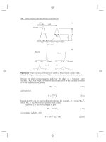
5.1 GPS point positioning
GPS point positioning, also known as standalone or autonomous position-
ing, involves only one GPS receiver. That is, one GPS receiver simultane-
ously tracks four or more GPS satellites to determine its own coordinates
with respect to the center of the Earth (Figure 5.1). Almost all of the GPS
receivers currently available on the market are capable of displaying their
point-positioning coordinates.
To determine the receivers point position at any time, the satellite
coordinates as well as a minimum of four ranges to four satellites are
required [2]. The receiver gets the satellite coordinates through the naviga-
tion message, while the ranges are obtained from either the C/A-code or
the P(Y)-code, depending on the receiver type (civilian or military). As
mentioned before, the measured pseudoranges are contaminated by both
the satellite and receiver clock synchronization errors. Correcting the satel-
lite clock errors may be done by applying the satellite clock correction in
the navigation message; the receiver clock error is treated as an additional
unknown parameter in the estimation process [2]. This brings the total
number of unknown parameters to four: three for the receiver coordinates
and one for the receiver clock error. This is the reason why at least four sat-
ellites are needed. It should be pointed out that if more than four satellites
are tracked, the so-called least-squares estimation or Kalman filtering tech-
nique is applied [24]. As the satellite coordinates are given in the WGS 84
system, the obtained receiver coordinates will be in the WGS 84 system as
70 Introduction to GPS
Known: X, Y, Z (satellites)
+R
1
,R
2
,R
3
,R
4
Unknown: X, Y, Z (receiver)
+ receiver clock error
Horizontal accuracy: 22m (95% of the time)
R
4
R
3
R
2
R
1
Figure 5.1 Principle of GPS point positioning.
well, as explained in Chapter 4. However, most GPS receivers provide the
transformation parameters between WGS 84 and many local datums used
around the world.
5.2 GPS relative positioning
GPS relative positioning, also called differential positioning, employs two
GPS receivers simultaneously tracking the same satellites to determine
their relative coordinates (Figure 5.2). Of the two receivers, one is selected
as a reference, or base, which remains stationary at a site with precisely
known coordinates. The other receiver, known as the rover or remote
receiver, has its coordinates unknown. The rover receiver may or may not
be stationary, depending on the type of the GPS operation.
A minimum of four common satellites is required for relative position-
ing. However, tracking more than four common satellites simultaneously
would improve the precision of the GPS position solution [2]. Carrier-
phase and/or pseudorange measurements can be used in relative posi-
tioning. A variety of positioning techniques are used to provide a
GPS Positioning Modes 71
Known: X, Y, Z (satellites)
+ R,R,R,R
1234
+ X, Y, Z (base)
Unknown: X, Y, Z
(remote)
R
1
R
2
R
3
R
4
D
Figure 5.2 Principle of GPS relative positioning.
postprocessing (postmission) or real-time solution. Details of the com-
monly used relative positioning techniques are given in Sections 5.3 to 5.7.
GPS relative positioning provides a higher accuracy than that of autono-
mous positioning. Depending on whether the carrier-phase or the pseu-
dorange measurements are used in relative positioning, an accuracy level of
a subcentimeter to a few meters can be obtained. This is mainly because the
measurements of two (or more) receivers simultaneously tracking a par-
ticular satellite contain more or less the same errors and biases [5]. The
shorter the distance between the two receivers, the more similar the errors.
Therefore, if we take the difference between the measurements of the two
receivers (hence the name differential positioning), the similar errors
will be removed or reduced.
5.3 Static GPS surveying
Static GPS surveying is a relative positioning technique that depends on the
carrier-phase measurements [2]. It employs two (or more) stationary
receivers simultaneously tracking the same satellites (see Figure 5.3). One
receiver, the base receiver, is set up over a point with precisely known coor-
dinates such as a survey monument (sometimes referred to as the known
point). The other receiver, the remote receiver, is set up over a point whose
coordinates are sought (sometimes referred to as the unknown point). The
base receiver can support any number of remote receivers, as long as a
minimum of four common satellites is visible at both the base and the
remote sites.
In principle, this method is based on collecting simultaneous measure-
ments at both the base and remote receivers for a certain period of time,
which, after processing, yield the coordinates of the unknown point. The
observation, or occupation, time varies from about 20 minutes to a few
hours, depending on the distance between the base and the remote receiv-
ers (i.e., the baseline length), the number of visible satellites, and the satel-
lite geometry. The measurements are usually taken at a recording interval
of 15 or 20 seconds, or one sample measurement every 15 or 20 seconds.
After completing the field measurements, the collected data is down-
loaded from the receivers into the PC for processing. Different processing
options may be selected depending on the user requirements, the baseline
length, and other factors. For example, if the baseline is relatively short, say,
72 Introduction to GPS
15 or 20 km, resolving the ambiguity parameters would be a key issue to
ensure high-precision positioning. As such, in this case the option of fix-
ing the ambiguity parameters should be selected. In contrast, if the baseline
is relatively long, a user may select the ionosphere-free linear combination
option to remove the majority of the ionospheric error (see Chapter 2
for details on the various linear combinations of the GPS observables). This
is because the ambiguity parameters may not be fixed reliably at the correct
integer values. For very long baselines, for example, over 1,000 km, it is
recommended that the user processes the data with one of the scientific
software packages available, such as the BERENSE software developed
by the University of Bern, rather than a commercial software package.
The precise ephemeris should also be used in this case, as the effect of
the orbital errors will be considerably different at the two ends of the
baseline.
Static GPS surveying with the carrier-phase measurements is the
most accurate positioning technique. This is mainly due to the significant
change in satellite geometry over the long observation time span. Although
both the single- and dual-frequency receivers can be used for static posi-
tioning, the latter is often used, especially for baselines exceeding 20 km.
GPS Positioning Modes 73
Base
(
unknown
)
Remote
(unknown)
Figure 5.3 Static GPS surveying.
TEAMFLY
Team-Fly
®
The expected accuracy from a geodetic quality receiver is typically 5 mm +
1 ppm (rms), ppm for parts per million and rms for root-mean-square.
That is, for a 10-km baseline, for example, the expected accuracy of the
static GPS surveying is 1.5 cm (rms). Higher accuracy may be obtained by,
for example, applying the precise ephemeris.
5.4 Fast (rapid) static
Fast, or rapid, static surveying is a carrier-phasebased relative positioning
technique similar to static GPS surveying. That is, it employs two or more
receivers simultaneously tracking the same satellites. However, with rapid
static surveying, only the base receiver remains stationary over the known
point during the entire observation session (see Figure 5.4). The rover
receiver remains stationary over the unknown point for a short period of
time only, and then moves to another point whose coordinates are sought
[2]. Similar to the static GPS surveying, the base receiver can support any
number of rovers.
This method is suitable when the survey involves a number of
unknown points located in the vicinity (i.e., within up to about 15 km) of
a known point. The survey starts by setting up the base receiver over the
74 Introduction to GPS
Base
(fixed)
Rover
(moving)
Figure 5.4 Fast (rapid) static GPS surveying.
known point, while setting up the rover receiver over the first unknown
point (Figure 5.4). The base receiver remains stationary and collects
data continuously. The rover receiver collects data for a period of about
2 to 10 minutes, depending on the distance to the base as well as the
satellite geometry [2]. Once the rover receiver has collected the data,
the user moves to the following point with unknown coordinates and
repeats the procedures. It should be pointed out that, while moving,
the rover receiver may be turned off. Due to the relatively short occupa-
tion time for the rover receiver, the recording interval is reduced to
5 seconds.
After collecting and downloading the field data from both receivers,
the PC software is used for data processing. Depending on whether enough
common data was collected, the software may output a fixed solution,
which indicates that the ambiguity parameters were fixed at integer values
(see Chapter 6 for details). Otherwise, a float solution is obtained, which
means that the software was unable to fix ambiguity parameters at integer
values (i.e., only real-valued ambiguity parameters were obtained). This
problem occurs mainly when the collected GPS data is insufficient. A fixed
solution means that the positioning accuracy is at the centimeter level,
while the float solution means that the positioning accuracy is at the deci-
meter or submeter level. Although both the single- and dual-frequency
receivers can be used for fast static surveying, the probability of getting a
fixed solution is higher with the latter.
5.5 Stop-and-go GPS surveying
Stop-and-go surveying is another carrier-phase-based relative positioning
technique. It also employs two or more GPS receivers simultaneously
tracking the same satellites (Figure 5.5): a base receiver that remains sta-
tionary over the known point and one or more rover receivers [2]. The
rover receiver travels between the unknown points, and makes a brief stop
at each point to collect the GPS data. The data is usually collected at a 1- to
2-second recording rate for a period of about 30 seconds per each stop.
Similar to the previous methods, the base receiver can support any number
of rovers. This method is suitable when the survey involves a large number
of unknown points located in the vicinity (i.e., within up to 1015 km) of a
known point.
GPS Positioning Modes 75
The survey starts by first determining the initial integer ambiguity
parameters, a process known as receiver initialization. This could be done
by various methods, discussed in the next chapter. Once the initialization
is performed successfully, centimeter-level positioning accuracy can be
obtained instantaneously. This is true as long as there is a minimum of four
common satellites simultaneously tracked by both the base and the rover
receivers at all times. If this condition is not fulfilled at any moment during
the survey, the initialization process must be repeated to ensure centi-
meter-level accuracy.
Following the initialization, the rover moves to the first unknown
point. After collecting about 30 seconds of data, the rover moves, without
being switched off, to the second point and the procedures are repeated. It
is of utmost importance that at least four satellites are tracked, even during
the move; otherwise the initialization process must be repeated again by,
for example, reoccupying the previous point. Some manufacturers, for
example, Ashtech Inc., recommend the reoccupation of the first point at
the end of the survey. This turned out to be very useful in obtaining a fixed
solution provided that the processing software has the forward and back-
ward processing functions. Once the data is collected and downloaded, PC
software is used to process it. Some software packages have the forward and
backward processing functions, which help in obtaining a fixed solution,
76 Introduction to GPS
Base
(fixed)
Rover
(moving)
Figure 5.5 Stop-and-go GPS surveying.
or centimeter-level accuracy. Both single- and dual-frequency receivers
may use the stop-and-go surveying method.
A special case of stop-and-go surveying is known as kinematic GPS
surveying. Both methods are the same in principle; however, the latter
requires no stops at the unknown points. The positional accuracy is
expected to be higher with the stop-and-go surveying, as the errors are
averaged out when the receiver stops at the unknown points.
5.6 RTK GPS
RTK surveying is a carrier phasebased relative positioning technique that,
like the previous methods, employs two (or more) receivers simultane-
ously tracking the same satellites (Figure 5.6). This method is suitable
when: (1) the survey involves a large number of unknown points located in
the vicinity (i.e., within up to about 1015 km) of a known point; (2) the
coordinates of the unknown points are required in real time; and (3) the
line of sight, the propagation path, is relatively unobstructed [6]. Because
GPS Positioning Modes 77
D
Base
Rover
Radio
Accuracy:
~ 25 cm
Figure 5.6 RTK GPS surveying.
of its ease of use as well as its capability to determine the coordinates in real
time, this method is the preferred method by many users.
In this method, the base receiver remains stationary over the known
point and is attached to a radio transmitter (Figure 5.6). The rover receiver
is normally carried in a backpack and is attached to a radio receiver. Similar
to the conventional kinematic GPS method, a data rate as high as 1 Hz (one
sample per second) is required. The base receiver measurements and coor-
dinates are transmitted to the rover receiver through the communication
(radio) link [7, 8]. The built-in software in a rover receiver combines and
processes the GPS measurements collected at both the base and the rover
receivers to obtain the rover coordinates.
The initial ambiguity parameters are determined almost instantane-
ously using a technique called on-the-fly (OTF) ambiguity resolution, to
be discussed in the next chapter. Once the ambiguity parameters are fixed
to integer values, the receiver (or its handheld computer controller) will
display the rover coordinates right in the field. That is, no postprocessing is
required. The expected positioning accuracy is of the order of 2 to 5 cm
(rms). This can be improved by staying over the point for a short period of
time, for example, about 30 seconds, to allow for averaging the position.
The computed rover coordinates for the entire survey may be stored and
downloaded at a later time into CAD software for further analysis. This
method is used mainly, but not exclusively, with dual-frequency receivers.
Under the same conditions, the positioning accuracy of the RTK
method is slightly degraded compared with that of the conventional kine-
matic GPS method. This is mainly because the time tags (or time stamps)
of the conventional kinematic data from both the base and the rover match
perfectly in the processing. With RTK, however, the base receiver data
reaches the rover after some delay (or latency). Data latency occurs as a
result of formatting, packetizing, transmitting, and decoding the base data
[7]. To match the time tag of the rover data, the base data must be extrapo-
lated, which degrades the positioning accuracy.
5.7 Real-time differential GPS
Real-time differential GPS (DGPS) is a code-based relative positioning
technique that employs two or more receivers simultaneously tracking the
same satellites (Figure 5.7). It is used when a real-time meter-level accuracy
78 Introduction to GPS
is enough. The method is based on the fact that the GPS errors in the meas-
ured pseudoranges are essentially the same at both the base and the rover,
as long as the baseline length is within a few hundred kilometers.
As before, the base receiver remains stationary over the known point.
The built-in software in the base receiver uses the precisely known base
coordinates as well as the satellite coordinates, derived from the navigation
message, to compute the ranges to each satellite in view. The software fur-
ther takes the difference between the computed ranges and the measured
code pseudoranges to obtain the pseudorange errors (or DGPS correc-
tions). These corrections are transmitted in a standard format called Radio
Technical Commission for Maritime Service (RTCM) to the rover through
a communication link (see Chapter 8 for more about RTCM). The rover
then applies the DGPS corrections to correct the measured pseudoranges
at the rover. Finally, the corrected pseudoranges are used to compute the
rover coordinates.
The accuracy obtained with this method varies between a submeter
and about 5m, depending on the base-rover distance, the transmission rate
of the RTCM DGPS corrections, and the performance of the C/A-code
receivers [2]. Higher accuracy is obtained with short base-rover separation,
GPS Positioning Modes 79
Base
Rover
Accuracy: submeter to ~ 5m
Radio
Figure 5.7 Real-time differential GPS operation.
high transmission rate, and carrier-smoothed C/A-code ranges. With the
termination of selective availability, the data rate could be reduced to 10
seconds or lower without noticeable accuracy degradation. Further accu-
racy improvement could be achieved if the receivers are capable of storing
the raw pseudorange measurements, which could be used at a later time in
the postprocessing mode. As the real-time DGPS is widely used, some gov-
ernmental agencies as well as private firms are providing the RTCM DGPS
corrections either at no cost or at certain fees. More about these services
will be given in Chapter 7.
5.8 Real time versus postprocessing
The term real time means that the results are obtained almost instantane-
ously, while the term postprocessing means that the measurements are col-
lected in the field and processed at a later time to obtain the results. Each of
these modes has some advantages and some disadvantages.
The first advantage of the real-time mode is that the results as well as
the accuracy measures (or quality control) are obtained while in the field.
This is especially important for RTK surveying, as the user would not
store the displayed coordinates unless the ambiguity parameters are
shown to be fixed at integer values and centimeter-level accuracy is
achieved. This leads to a higher productivity compared with the post-
processing mode, as only enough GPS data to obtain a fixed solution is
collected. In addition, processing the GPS data is done automatically in
the field by the built-in software. This means that no postprocessing soft-
ware training is required. The user also saves the time spent in data
processing.
There are, however, some advantages in the postprocessing mode as
well. The first of these is that more accurate results are generally obtained
with the postprocessing mode. One reason for this is more flexibility in
editing and cleaning of the collected GPS data. As well, there is no accuracy
degradation due to data latency, as explained in Section 5.7. Another
important advantage is that the communication link problems, such as
the relatively unobstructed line-of-sight requirement, are avoided. In
some cases, the input parameters, such as the base station coordinates or
the antenna height, may contain some errors, which lead to errors in
the computed rover coordinates. These errors can be corrected in the
80 Introduction to GPS
postprocessing mode, while they cannot be completely corrected in the
real-time mode.
5.9 Communication (radio) link
RTK and real-time DGPS operations require a communication, or radio,
link to transmit the information from the base receiver to the rover receiver
(Figures 5.6 and 5.7). RTK data are typically transmitted at a baud rate of
9,600, while the DGPS corrections are typically transmitted at 200 Kbps. A
variety of radio links that use different parts of the electromagnetic spec-
trum are available to support such operations. The spectrum parts mostly
used in practice are the low/medium frequency (LF/MF) bands (i.e., 30
kHz to 3 MHz) and the very high and ultrahigh frequency (VHF/UHF)
bands (i.e., 30 MHz to 3 GHz) [7, 8]. Often, GPS users utilize their own
dedicated radio links to transmit base station information.
Dedicated ground-based GPS radio links are mostly established using
the VHF/UHF band. Radio links in this band provide line-of-sight cover-
age, with the ability to penetrate into buildings and other obstructions.
One example of such a radio link is the widely used RFM96W from
Pacific Crest Corporation, which is available in different models based on
the supported frequencies in the VHF/UHF band. This type of radio link
requires a license to operate. A new radio link that was recently produced
by the same company is called the Position Data Link (PDL) (see Figure
5.8). PDL allows for a baud rate of 19,200, and is characterized by low
power consumption and enhanced user interface. Another example is the
license-free spread-spectrum radio transceiver, which operates in the
902928 MHz portion of the UHF band (Figure 5.8). This radio link has
coverage of 15 km and 315 km in urban and rural areas, respectively.
More recently, some GPS manufacturers adopted cellular technology,
the digital Personal Communication Services (PCS), as an alternative
communication link. In the near future, it is expected that the third-
generation (3G) wideband digital networks will be used extensively as the
GPS communication link. The 3G technology uses common global stan-
dards, which reduces the service cost. In addition, this technology allows
the devices to be kept in the on position all the time for data transmis-
sion or reception, while the subscribers pay for the packets of data they
transmit/receive.
GPS Positioning Modes 81
It should be pointed out that obstructions along the propagation path,
such as buildings and terrain, attenuate the transmitted signal, which leads
to limited signal coverage. The transmitted signal attenuation may also be
caused by ground reflection (multipath), the transmitting antenna, and
other factors [7]. To increase the coverage of a radio link, a user may
82 Introduction to GPS
Figure 5.8 Examples of radio modems. (Courtesy of Magellan Corporation.)
Base
Rover
Repeater
Figure 5.9 Use of repeaters to increase radio coverage.
employ a power amplifier or high-quality coaxial cables, or he or she may
increase the height of the transmitting/receiving radio antenna. If a user
employs a power amplifier, however, he or she should be cautioned against
signal overload, which usually occurs when the transmitting and the
receiving radios are very close to each other [7].
A user may also increase the signal coverage by using a repeater station.
In this case, it might be better to use a unidirectional antenna, such as a
Yagi, at the base station and an omnidirectional antenna at the repeater sta-
tion (see Figure 5.9) [8].
References
[1] Shaw, M., K. Sandhoo, and D. Turner, Modernization of the Global
Positioning System, GPS World, Vol. 11, No. 9, September 2000,
pp. 3644.
[2] Hoffmann-Wellenhof, B., H. Lichtenegger, and J. Collins, Global
Positioning System: Theory and Practice, 3rd ed., New York:
Springer-Verlag, 1994.
[3] Leick, A., GPS Satellite Surveying, 2nd ed., New York: Wiley, 1995.
[4] Levy, L. J., The Kalman Filter: Navigations Integration Workhorse, GPS
World, Vol. 8, No. 9, September 1997, pp. 6571.
[5] Langley, R. B., The GPS Observables, GPS World,Vol.4,No.4,April
1993, pp. 5259.
[6] Langley, R. B., RTK GPS, GPS World, Vol. 9, No. 9, September 1998,
pp. 7076.
[7] Langley, R. B., Communication Links for DGPS, GPS World,Vol.4,
No. 5, May 1993, pp. 4751.
[8] Pacific Crest Corporation, The Guide to Wireless GPS Data Links, 2000.
GPS Positioning Modes 83
TEAMFLY
Team-Fly
®