ccna study guide by sybex phần 3 ppsx
Bạn đang xem bản rút gọn của tài liệu. Xem và tải ngay bản đầy đủ của tài liệu tại đây (5.78 MB, 75 trang )
TCP/IP and the DoD Model 111
UDP receives upper-layer blocks of information, instead of data streams
as TCP does, and breaks them into segments. Like TCP, each UDP segment
is given a number for reassembly into the intended block at the destination.
However, UDP does not sequence the segments and does not care in which
order the segments arrive at the destination. At least it numbers them,
though. But after that, UDP sends the segments off and forgets about them.
It doesn’t follow through, check up on them, or even allow for an acknowl-
edgment of safe arrival—complete abandonment. Because of this, it’s
referred to as an unreliable protocol. This does not mean that UDP is inef-
fective, only that it doesn’t handle issues of reliability.
Further, UDP doesn’t create a virtual circuit, nor does it contact the des-
tination before delivering information to it. It is, therefore, also considered
a connectionless protocol. Since UDP assumes that the application will use
its own reliability method, it doesn’t use any. This gives an application devel-
oper a choice when running the Internet Protocol stack: TCP for reliability
or UDP for faster transfers.
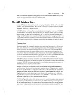
UDP Segment Format
The very low overhead of UDP compared to TCP, which doesn’t use win-
dowing or acknowledgments, is shown in Figure 3.4.
FIGURE 3.4 UDP segment
You need to understand what each field in the UDP segment is. The UDP
segment contains the following fields:
Source port Port number of the host sending the data
Destination port Port number of the application requested on the desti-
nation host
Bit 0 Bit 15
Source port (16) Destination port (16)
Length (16) Checksum (16)
Data (if any)
Bit 16 Bit 31
8 bytes
Copyright ©2000 SYBEX , Inc., Alameda, CA
www.sybex.com
112 Chapter 3
Internet Protocol
Length of the segment Length of UDP header and UDP data
CRC Checksum of both the UDP header and UDP data fields
Data Upper-layer data
UDP, like TCP, doesn’t trust the lower layers and runs its own CRC.
Remember that the Frame Check Sequence (FCS) is the field that houses the
CRC, which is why you can see the FCS information.
The following shows a UDP segment caught on a network analyzer:
UDP - User Datagram Protocol
Source Port: 1085
Destination Port: 5136
Length: 41
Checksum: 0x7a3c
UDP Data Area:
Z 00 01 5a 96 00 01 00 00 00 00 00 11
00 00 00
C 2 _C._C 2e 03 00 43 02 1e 32 0a 00 0a 00 80 43
00 80
Frame Check Sequence: 0x00000000
Notice the low overhead! Try to find the sequence number, ack number,
and window size. You will notice that these are absent from the UDP segment.
Key Concepts of Host-to-Host Protocols
Since we have seen both a connection-oriented (TCP) and connectionless
(UDP) protocol in action, it would be good to summarize the two here. The
following list highlights some of the key concepts that you should keep in
mind regarding these two protocols.
TCP UDP
Sequenced Unsequenced
Reliable Unreliable
Connection-oriented Connectionless
Virtual circuit Low overhead
Copyright ©2000 SYBEX , Inc., Alameda, CA
www.sybex.com
TCP/IP and the DoD Model 113
A telephone analogy might help you understand how TCP works. Most of
us know that before you speak to someone on a phone, you must first estab-
lish a connection with that other person—wherever they might be. This is
like a virtual circuit with the TCP protocol. If you were giving someone
important information during your conversation, you might ask, “Did you
get that?” A query like that is similar to a TCP acknowledgment. From time
to time, for various reasons, people also ask, “Are you still there?” They end
their conversations with a “goodbye” of some kind, putting closure on the
phone call. TCP also performs these types of functions.
Alternately, using UDP is like sending a postcard. To do that, you don’t
need to contact the other party first. You simply write your message, address
the postcard, and mail it. This is analogous to UDP’s connectionless orien-
tation. Since the message on the postcard is probably not a matter of life or
death, you don’t need an acknowledgment of its receipt. Similarly, UDP does
not involve acknowledgments.
Port Numbers
TCP and UDP must use port numbers to communicate with the upper layers.
Port numbers keep track of different conversations crossing the network
simultaneously. Originating-source port numbers are dynamically assigned
by the source host, which will be some number starting at 1024. 1023 and
below are defined in RFC 1700, which discusses what is called well-known
port numbers.
Virtual circuits that do not use an application with a well-known port
number are assigned port numbers randomly chosen from within a specific
range instead. These port numbers identify the source and destination host
in the TCP segment.
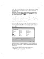
Figure 3.5 illustrates how both TCP and UDP use port numbers.
FIGURE 3.5 Port numbers for TCP and UDP
FTP Telnet Doom TFTP POP3DNS
TCP
Transport
layer
Application
layer
Port
numbers
UDP
News
1441106953
666
2321
Copyright ©2000 SYBEX , Inc., Alameda, CA
www.sybex.com
114 Chapter 3
Internet Protocol
The different port numbers that can be used are explained below:
Numbers below 1024 are considered well-known port numbers and
are defined in RFC 1700.
Numbers 1024 and above are used by the upper layers to set up ses-
sions with other hosts and by TCP to use as source and destination
addresses in the TCP segment.
TCP Session: Source Port
The following listing shows a TCP session captured with the Etherpeek ana-
lyzer software. Notice that the source host makes up the source port, which
in this case is 5972. The destination port is 23, which is used to tell the receiv-
ing host the purpose of the intended connection (Telnet).
TCP - Transport Control Protocol
Source Port: 5973
Destination Port: 23
Sequence Number: 1456389907
Ack Number: 1242056456
Offset: 5
Reserved: %000000
Code: %011000
Ack is valid
Push Request
Window: 61320
Checksum: 0x61a6
Urgent Pointer: 0
No TCP Options
TCP Data Area:
vL.5.+.5.+.5.+.5 76 4c 19 35 11 2b 19 35 11 2b 19 35
11 2b 19 35 +. 11 2b 19
Frame Check Sequence: 0x0d00000f
As you saw in the above TCP session, the source host makes up the source
port. But why is it that the source makes up a port number? The reason is to
differentiate between sessions with different hosts. How else would a server
know where information is coming from if it didn’t have a different number
from a sending host? TCP and the upper layers don’t use hardware and logical
Copyright ©2000 SYBEX , Inc., Alameda, CA
www.sybex.com
TCP/IP and the DoD Model 115
addresses to understand the sending host’s address like the Data Link and Net-
work layer protocols do. Instead, they use port numbers. It’s easy to imagine
the receiving host getting confused if all the hosts used the same port number
to get to FTP.
TCP Session: Destination Port
Now, typically you’ll look at an analyzer and see that only the source port
is above 1024 and the destination port is a well-known port, as shown in the
following Etherpeek trace:
TCP - Transport Control Protocol
Source Port: 1144
Destination Port: 80 World Wide Web HTTP
Sequence Number: 9356570
Ack Number: 0
Offset: 7
Reserved: %000000
Code: %000010
Synch Sequence
Window: 8192
Checksum: 0x57E7
Urgent Pointer: 0
TCP Options:
Option Type: 2 Maximum Segment Size
Length: 4
MSS: 536
Option Type: 1 No Operation
Option Type: 1 No Operation
Option Type: 4
Length: 2
Opt Value:
No More HTTP Data
Frame Check Sequence: 0x43697363
Notice that the source port is over 1024, but the destination port is 80, or
HTTP service. The server, or receiving host, will change the destination port
if it needs to.
Copyright ©2000 SYBEX , Inc., Alameda, CA
www.sybex.com
116 Chapter 3
Internet Protocol
In the preceding trace, a “syn” packet is sent to the destination device. The
syn sequence is telling the remote destination device that it wants to create a
session.
TCP Session: Syn Packet Acknowledgment
The next trace shows an acknowledgment to the syn packet. Notice the “Ack
is valid,” which means the source port was accepted and the device agreed to
create a virtual circuit with the originating host.
TCP - Transport Control Protocol
Source Port: 80 World Wide Web HTTP
Destination Port: 1144
Sequence Number: 2873580788
Ack Number: 9356571
Offset: 6
Reserved: %000000
Code: %010010
Ack is valid
Synch Sequence
Window: 8576
Checksum: 0x5F85
Urgent Pointer: 0
TCP Options:
Option Type: 2 Maximum Segment Size
Length: 4
MSS: 1460
No More HTTP Data
Frame Check Sequence: 0x6E203132
Notice that the response from the server shows the source is 80 and the des-
tination is the 1144 sent from the originating host.
The Internet Layer Protocols
There are two main reasons for the Internet layer’s existence: routing, and
providing a single network interface to the upper layers.
None of the upper- or lower-layer protocols have any functions relating to
routing. The complex and important task of routing is the job of the Internet
Copyright ©2000 SYBEX , Inc., Alameda, CA
www.sybex.com
TCP/IP and the DoD Model 117
layer. The Internet layer’s second job is to provide a single network interface
to the upper-layer protocols. Without this layer, application programmers
would need to write “hooks” into every one of their applications for each dif-
ferent Network Access protocol. This would not only be a pain in the neck, but
it would lead to different versions of each application—one for Ethernet,
another one for Token Ring, and so on. To prevent this, IP provides one single
network interface for the upper-layer protocols. That accomplished, it’s then
the job of IP and the various Network Access protocols to get along and work
together.
All network roads don’t lead to Rome—they lead to IP. And all the other
protocols at this layer, as well as all those at the upper layers, use it. Never
forget that. All paths through the model go through IP. The following sec-
tions describe the protocols at the Internet layer.
These are the protocols that work at the Internet layer:
Internet Protocol (IP)
Internet Control Message Protocol (ICMP)
Address Resolution Protocol (ARP)
Reverse Address Resolution Protocol (RARP)
Internet Protocol (IP)
The Internet Protocol (IP) essentially is the Internet layer. The other proto-
cols found here merely exist to support it. IP contains the big picture and
could be said to “see all,” in that it is aware of all the interconnected net-
works. It can do this because all the machines on the network have a soft-
ware, or logical, address called an IP address, which we’ll cover more
thoroughly later in this chapter.
IP looks at each packet’s address. Then, using a routing table, it decides
where a packet is to be sent next, choosing the best path. The Network
Access–layer protocols at the bottom of the model don’t possess IP’s enlight-
ened scope of the entire network; they deal only with physical links (local
networks).
Identifying devices on networks requires answering these two questions:
Which network is it on? And what is its ID on that network? The first answer
is the software, or logical, address (the correct street). The second answer is
the hardware address (the correct mailbox). All hosts on a network have a
logical ID called an IP address. This is the software, or logical, address and
Copyright ©2000 SYBEX , Inc., Alameda, CA
www.sybex.com
118 Chapter 3
Internet Protocol
contains valuable encoded information greatly simplifying the complex task
of routing. (Please note that IP is discussed in RFC 791.)
IP receives segments from the Host-to-Host layer and fragments them into
datagrams (packets). IP then reassembles datagrams back into segments on
the receiving side. Each datagram is assigned the IP address of the sender and
of the recipient. Each router (layer-3 device) that receives a datagram makes
routing decisions based upon the packet’s destination IP address.
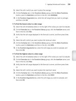
Figure 3.6 shows an IP header. This will give you an idea of what the IP
protocol has to go through every time user data is sent from the upper layers
and wants to be sent to a remote network.
FIGURE 3.6 IP header
The following fields make up the IP header:
Version IP version number.
HLEN Header length in 32-bit words.
Priority or ToS Type of Service tells how the datagram should be han-
dled. The first three bits are the priority bits.
Total length Length of the packet including header and data.
Identification Unique IP-packet value.
Bit 0 Bit 15
Total length (16)
Header checksum (16)Time to Live (8) Protocol (8)
Version
(4)
Flags
(3)
Header
length (4)
Priority and
Type of Service (8)
Identification (16) Fragment offset (13)
Options (0 or 32 if any)
Destination IP address (32)
Source IP address (32)
Data (varies if any)
Bit 16 Bit 31
20 bytes
Copyright ©2000 SYBEX , Inc., Alameda, CA
www.sybex.com
TCP/IP and the DoD Model 119
Flags Specifies whether fragmentation should occur.
Frag offset Provides fragmentation and reassembly if the packet is too
large to put in a frame. It also allows different Maximum Transmission
Units (MTUs) on the Internet.
TTL Time to Live is set into a packet when it is originally generated. It
gives it a time to live. If it doesn’t get to where it wants to go before the
TTL expires, boom—it’s gone. This stops IP packets from continuously
circling the network looking for a home.
Protocol Port of upper-layer protocol (TCP is port 6 or UDP is
port 17 (hex)).
Header checksum Cyclic Redundancy Check on header only.
Source IP address 32-bit IP address of sending station.
Destination IP address 32-bit IP address of the station this packet is des-
tined for.
IP option Used for network testing, debugging, security, and more.
Data Upper-layer data.
Here’s a snapshot of an IP packet caught on a network analyzer. Notice
that all the information discussed above appears here:
IP Header - Internet Protocol Datagram
Version: 4
Header Length: 5
Precedence: 0
Type of Service: %000
Unused: %00
Total Length: 187
Identifier: 22486
Fragmentation Flags: %010 Do Not Fragment
Fragment Offset: 0
Time To Live: 60
IP Type: 0x06 TCP
Header Checksum: 0xd031
Source IP Address: 10.7.1.30
Dest. IP Address: 10.7.1.10
No Internet Datagram Options
Copyright ©2000 SYBEX , Inc., Alameda, CA
www.sybex.com
120 Chapter 3
Internet Protocol
Notice that there are logical, or IP, addresses in this header.
The type field—it’s typically a protocol field, but this analyzer sees it as a
type field—is important. If the header didn’t carry the protocol information
for the next layer, IP wouldn’t know what to do with the data carried in the
packet.
Figure 3.7 shows how the Network layer sees the protocols at the Trans-
port layer when it needs to hand a packet to the upper-layer protocols.
FIGURE 3.7 The protocol field in an IP header
In this example, the protocol field tells IP to send the data to either TCP
port 6 or UDP port 17 (both hex addresses). However, it will only be UDP
or TCP if the data is part of a data stream headed for an upper-layer service
or application. It could just as easily be destined for ICMP (Internet Control
Message Protocol), ARP (Address Resolution Protocol), or some other type
of Network layer protocol.
Table 3.1 is a list of some other popular protocols that can be specified in
the protocol field.
TABLE 3.1 Possible Protocols Found in the Protocol Field of an IP Header
Protocol Protocol Number
ICMP 1
IGRP 9
IPv6 41
GRE 47
TCP UDP
Protocol
numbers
IP
Transport
layer
Internet
layer
176
Copyright ©2000 SYBEX , Inc., Alameda, CA
www.sybex.com
TCP/IP and the DoD Model
121
Internet Control Message Protocol (ICMP)
The
Internet Control Message Protocol (ICMP)
works at the Network layer and
is used by IP for many different services. ICMP is a management protocol and
messaging service provider for IP. Its messages are carried as IP datagrams.
RFC 1256,
ICMP Router Discovery Messages
, is an annex to ICMP, which
affords hosts’ extended capability in discovering routes to gateways.
Periodically, router advertisements are announced over the network,
reporting IP addresses for the router’s network interfaces. Hosts listen for
these network infomercials to acquire route information. A
router solicita-
tion
is a request for immediate advertisements and may be sent by a host
when it starts up. The following are some common events and messages that
ICMP relates to:
Destination Unreachable
If a router can’t send an IP datagram any fur-
ther, it uses ICMP to send a message back to the sender, advising it of the
situation. For example, if a router receives a packet destined for a network
that the router doesn’t know about, it will send an ICMP Destination
Unreachable message back to the sending station.
Buffer Full
If a router’s memory buffer for receiving incoming data-
grams is full, it will use ICMP to send out this message.
Hops
Each IP datagram is allotted a certain number of routers, called
hops,
that it may go through. If it reaches its limit of hops before arriving
at its destination, the last router to receive that datagram deletes it. The
executioner router then uses ICMP to send an obituary message, inform-
ing the sending machine of the demise of its datagram.
Ping
Packet Internet Groper uses ICMP echo messages to check the
physical connectivity of machines on an internetwork.
Traceroute
Using ICMP timeouts, traceroute is used to find a path a
packet takes as it traverses an internetwork.
The following data is from a network analyzer catching an ICMP echo
request. Notice that even though ICMP works at the Network layer, it still
IPX in IP 111
Layer-2 tunnel 115
TABLE 3.1
Possible Protocols Found in the Protocol Field of an IP Header
(continued)
Protocol Protocol Number
Copyright ©2000 SYBEX , Inc., Alameda, CA
www.sybex.com
122 Chapter 3
Internet Protocol
uses IP to do the Ping request. The type field in the IP header is 0x01h, which
specifies the ICMP protocol.
Flags: 0x00
Status: 0x00
Packet Length:78
Timestamp: 14:04:25.967000 05/06/1998
Ethernet Header
Destination: 00:a0:24:6e:0f:a8
Source: 00:80:c7:a8:f0:3d
Ether-Type:08-00 IP
IP Header - Internet Protocol Datagram
Version: 4
Header Length: 5
Precedence: 0
Type of Service: %000
Unused: %00
Total Length: 60
Identifier: 56325
Fragmentation Flags: %000
Fragment Offset: 0
Time To Live: 32
IP Type: 0x01 ICMP
Header Checksum: 0x2df0
Source IP Address: 100.100.100.2
Dest. IP Address: 100.100.100.1
No Internet Datagram Options
ICMP - Internet Control Messages Protocol
ICMP Type: 8 Echo Request
Code: 0
Checksum: 0x395c
Identifier: 0x0300
Sequence Number: 4352
ICMP Data Area:
abcdefghijklmnop 61 62 63 64 65 66 67 68 69 6a 6b 6c 6d
qrstuvwabcdefghi 71 72 73 74 75 76 77 61 62 63 64 65 66
Frame Check Sequence: 0x00000000
Copyright ©2000 SYBEX , Inc., Alameda, CA
www.sybex.com
TCP/IP and the DoD Model 123
If you remember reading about the Data Link layer and the different
frame types in Chapter 1, you should be able to look at the above trace and
tell me what type of Ethernet frame this is. The only fields are destination
hardware address, source hardware address, and Ether-type field. The only
frame that uses an Ether-type field is an Ethernet_II frame. (SNAP uses an
Ether-type field also, but only within an 802.2 LLC field, which is not
present in the frame.)
Address Resolution Protocol (ARP)
The Address Resolution Protocol (ARP) finds the hardware address of a host
from a known IP address. Here’s how it works: When IP has a datagram to
send, it must inform a Network Access protocol, such as Ethernet or Token
Ring, of the destination’s hardware address on the local network. (It has
already been informed by upper-layer protocols of the destination’s IP
address.) If IP doesn’t find the destination host’s hardware address in the
ARP cache, it uses ARP to find this information.
As IP’s detective, ARP interrogates the local network by sending out a
broadcast asking the machine with the specified IP address to reply with its
hardware address. In other words, ARP translates the software (IP) address
into a hardware address—for example, the destination machine’s Ethernet
board address—and from it, deduces its whereabouts. This hardware address
is technically referred to as the media access control (MAC) address or physical
address. Figure 3.8 shows how an ARP might look to a local network.
FIGURE 3.8 Local ARP broadcast
I need the Ethernet
address of 10.1.1.2
I heard that broadcast.
The message is for me.
Here is my Ethernet address.
10.1.1.1 10.1.1.2
IP: 10.1.1.2 = ???
IP: 10.1.1.2
Ethernet: 4523.7985.7734
Copyright ©2000 SYBEX , Inc., Alameda, CA
www.sybex.com
124 Chapter 3
Internet Protocol
ARP resolves IP addresses to Ethernet addresses.
The following trace shows an ARP broadcast. Notice that the destination
hardware address is unknown and is all Fs in hex, which is all 1s in binary,
and a hardware address broadcast.
Flags: 0x00
Status: 0x00
Packet Length:64
Timestamp: 09:17:29.574000 01/04/2000
Ethernet Header
Destination: FF:FF:FF:FF:FF:FF Ethernet Broadcast
Source: 00:A0:24:48:60:A5
Protocol Type:0x0806 IP ARP
ARP - Address Resolution Protocol
Hardware: 1 Ethernet (10Mb)
Protocol: 0x0800 IP
Hardware Address Length: 6
Protocol Address Length: 4
Operation: 1 ARP Request
Sender Hardware Address: 00:A0:24:48:60:A5
Sender Internet Address: 172.16.10.3
Target Hardware Address: 00:00:00:00:00:00 (ignored)
Target Internet Address: 172.16.10.10
Extra bytes (Padding):
0A 0A 0A 0A 0A 0A 0A 0A 0A 0A 0A 0A 0A
0A 0A 0A 0A 0A
Frame Check Sequence: 0x00000000
Reverse Address Resolution Protocol (RARP)
When an IP machine happens to be a diskless machine, it has no way of ini-
tially knowing its IP address, but it does know its MAC address. The Reverse
Address Resolution Protocol (RARP) discovers the identity of the IP address
for diskless machines by sending out a packet that includes its MAC address
and a request for the IP address assigned to that MAC address. A designated
Copyright ©2000 SYBEX , Inc., Alameda, CA
www.sybex.com
IP Addressing 125
machine, called a RARP server, responds with the answer, and the identity
crisis is over. RARP uses the information it does know about the machine’s
MAC address to learn its IP address and complete the machine’s ID portrait.
RARP resolves Ethernet addresses to IP addresses.
Figure 3.9 shows a diskless workstation asking for its IP address with a
RARP broadcast.
FIGURE 3.9 RARP broadcast example
IP Addressing
One of the most important topics in any discussion of TCP/IP is IP
addressing. An IP address is a numeric identifier assigned to each machine on
an IP network. It designates the location of a device on the network. An IP
address is a software address, not a hardware address—the latter is hard-
coded on a network interface card (NIC) and used for finding hosts on a
local network. IP addressing was designed to allow a host on one network to
communicate with a host on a different network, regardless of the type of
LANs the hosts are participating in.
What's my IP
address?
I heard that broadcast.
Your IP address
is 192.168.10.3
Ethernet: 4523.7985.7734 IP = ????
Ethernet: 4523.7985.7734
IP: 192.168.10.3
Copyright ©2000 SYBEX , Inc., Alameda, CA
www.sybex.com
126 Chapter 3
Internet Protocol
Before we get into the more complicated aspects of IP addressing, you
need to understand some of the basics. In this section you will learn about
some of the fundamentals of IP addressing and its terminology. Later on, you
will learn about the hierarchical IP addressing scheme and subnetting.
To understand IP addressing and subnetting, it’s important to have already
mastered binary-to-decimal conversion and the powers of 2. If you need to
review these topics, see the upcoming sidebars covering these issues.
IP Terminology
Throughout this chapter you will learn several terms that are critical to under-
standing the Internet Protocol. To start, here are a few of the most important:
Bit One digit; either a 1 or a 0.
Byte 7 or 8 bits, depending on whether parity is used. For the rest of this
chapter, always assume a byte is 8 bits.
Octet Always 8 bits. Base-8 addressing scheme.
Network address The designation used in routing to send packets to a
remote network, for example, 10.0.0.0, 172.16.0.0, and 192.168.10.0.
Broadcast address Used by applications and hosts to send information
to all nodes on a network. Examples include 255.255.255.255, which is
all networks, all nodes; 172.16.255.255, which is all subnets and hosts on
network 17.16.0.0; and 10.255.255.255, which broadcasts to all subnets
and hosts on network 10.0.0.0.
The Hierarchical IP Addressing Scheme
An IP address consists of 32 bits of information. These bits are divided into
four sections, referred to as octets or bytes, each containing 1 byte (8 bits).
You can depict an IP address using one of three methods:
Dotted-decimal, as in 172.16.30.56
Binary, as in 10101100.00010000.00011110.00111000
Hexadecimal, as in 82 39 1E 38
Copyright ©2000 SYBEX , Inc., Alameda, CA
www.sybex.com
IP Addressing 127
All these examples represent the same IP address. Although hexadecimal is not
used as often as dotted-decimal or binary when IP addressing is discussed, you
still might find an IP address stored in hexadecimal in some programs; for
example, the Windows Registry stores a machine’s IP address in hex.
The 32-bit IP address is a structured or hierarchical address, as opposed
to a flat or nonhierarchical, address. Although either type of addressing
scheme could have been used, the hierarchical variety was chosen for a good
reason. The advantage of this scheme is that it can handle a large number of
addresses, namely 4.3 billion (a 32-bit address space with two possible val-
ues for each position—either 0 or 1—gives you 2
32
, or approximately 4.3 bil-
lion). The disadvantage of this scheme, and the reason it’s not used for IP
addressing, relates to routing. If every address were unique, all routers on
the Internet would need to store the address of each and every machine
on the Internet. This would make efficient routing impossible, even if only a
fraction of the possible addresses were used.
The solution to this dilemma is to use a two- or three-level, hierarchical
addressing scheme that is structured by network and host, or network, sub-
net, and host.
This two- or three-level scheme is comparable to a telephone number. The
first section, the area code, designates a very large area. The second section,
the prefix, narrows the scope to a local calling area. The final segment, the
customer number, zooms in on the specific connection. IP addresses use the
same type of layered structure. Rather than all 32 bits being treated as a
unique identifier, as in flat addressing, a part of the address is designated as
the network address, and the other part is designated as either the subnet and
host or just the node address.
Network Addressing
The network address uniquely identifies each network. Every machine on the
same network shares that network address as part of its IP address. In the IP
address 172.16.30.56, for example, 172.16 is the network address.
The node address is assigned to, and uniquely identifies, each machine on
a network. This part of the address must be unique because it identifies a par-
ticular machine—an individual—as opposed to a network, which is a group.
This number can also be referred to as a host address. In the sample IP
address 172.16.30.56, .30.56 is the node address.
The designers of the Internet decided to create classes of networks based
on network size. For the small number of networks possessing a very large
Copyright ©2000 SYBEX , Inc., Alameda, CA
www.sybex.com
128 Chapter 3
Internet Protocol
number of nodes, they created the rank Class A network. At the other
extreme is the Class C network, which is reserved for the numerous networks
with a small number of nodes. The class distinction for networks between
very large and very small is predictably called the Class B network.
Subdividing an IP address into a network and node address is determined
by the class designation of one’s network. Figure 3.10 summarizes the three
classes of networks, which will be described in much more detail throughout
this chapter.
FIGURE 3.10 Summary of the three classes of networks
To ensure efficient routing, Internet designers defined a mandate for the
leading-bits section of the address for each different network class. For
example, since a router knows that a Class A network address always starts
with a 0, the router might be able to speed a packet on its way after reading
only the first bit of its address. This is where the address schemes define the
difference between a Class A, Class B, and Class C address.
Network Address Range: Class A
The designers of the IP address scheme said that the first bit of the first byte
in a Class A network address must always be off, or 0. This means a Class
A address must be between 0 and 127.
Here is how those numbers are defined:
0xxxxxxx: If we turn the other 7 bits all off and then turn them all on,
we will find your Class A range of network addresses.
00000000=0
01111111=127
Network Host Host Host
Network Network Host Host
Network Network Network Host
Multicast
Research
Class A:
Class B:
Class C:
Class D:
Class E:
8 bits 8 bits 8 bits 8 bits
Copyright ©2000 SYBEX , Inc., Alameda, CA
www.sybex.com
IP Addressing 129
So, a Class A network is defined in the first octet between 0 and 127. It
can’t be less or more. (We’ll talk about illegal addresses in a minute.)
If you are having any difficulty with the binary-to-decimal conversions, please
read the “Binary-to-Decimal Conversion Review” sidebar.
Binary-to-Decimal Conversion Review
Prior to learning about IP addressing, you must have a fundamental under-
standing of binary-to-decimal conversions. Here is how it works: Binary
numbers use 8 bits to define a decimal number. These bits are weighted
from right to left in an increment that doubles in value.
Here is an example of 8 bits and the value assigned to each bit:
128 64 32 16 8 4 2 1
Here is an example of binary-to-decimal conversion:
128 64 32 16 8 4 2 1 Binary value
0 0 1 0 0 1 1 0 Byte in binary
Add the value of the bits that are turned on:
32
4
2
=38
Any time you find a bit turned on (a one), you add the values of each bit
position. Let’s practice on a few more:
01010101=85
64
16
4
1
=85
Copyright ©2000 SYBEX , Inc., Alameda, CA
www.sybex.com
130 Chapter 3
Internet Protocol
Network Address Range: Class B
In a Class B network, the RFCs state that the first bit of the first byte must
always be turned on, but the second bit must always be turned off. If you
turn the other six bits all off and then all on, you will find the range for a
Class B network:
10000000=128
10111111=191
As you can see, this means that a Class B network can be defined when the
first byte is configured from 128 to 191.
Network Address Range: Class C
For Class C networks, the RFCs define the first two bits of the first octet
always turned on, but the third bit can never be on. Following the same pro-
cess as the previous classes, convert from binary to decimal to find the range.
Here is the range for a Class C network:
11000000=192
11011111=223
Try a few on your own:
00001111=15
10001100=140
11001100=204
You will need to memorize the binary-to-decimal conversions in the follow-
ing list. You will use this information when you practice subnetting later in
this chapter:
00000000=0
10000000=128
11000000=192
11100000=224
11110000=240
11111000=248
11111100=252
11111110=254
11111111=255
Copyright ©2000 SYBEX , Inc., Alameda, CA
www.sybex.com
IP Addressing 131
So, if you see an IP address that starts at 192 and goes to 223, you’ll know
it is a Class C IP address.
Network Address Ranges: Classes D and E
The addresses between 224 and 255 are reserved for Class D and E net-
works. Class D is used for multicast addresses and Class E for scientific pur-
poses. We will not discuss Class D and E addresses in this book.
Network Addresses: Special Purpose
Some IP addresses are reserved for special purposes, and network adminis-
trators shouldn’t assign these addresses to nodes. Table 3.2 lists the members
of this exclusive little club and why they’re included in it.
TABLE 3.2 Reserved IP Addresses
Address Function
Network address of all 0s Interpreted to mean “this network
or segment.”
Network address of all 1s Interpreted to mean “all networks.”
Network 127.0.0.1 Reserved for loopback tests. Desig-
nates the local node and allows that
node to send a test packet to itself
without generating network traffic.
Node address of all 0s Interpreted to mean “this node.”
Node address of all 1s Interpreted to mean “all nodes” on
the specified network; for example,
128.2.255.255 means “all nodes”
on network 128.2 (Class B address).
Entire IP address set to all 0s Used by Cisco routers to designate
the default route.
Entire IP address set to all 1s (same
as 255.255.255.255)
Broadcast to all nodes on the cur-
rent network; sometimes called an
“all 1s broadcast.”
Copyright ©2000 SYBEX , Inc., Alameda, CA
www.sybex.com
132 Chapter 3
Internet Protocol
Class A Addresses
In a Class A network address, the first byte is assigned to the network
address, and the three remaining bytes are used for the node addresses. The
Class A format is
Network.Node.Node.Node
For example, in the IP address 49.22.102.70, 49 is the network address,
and 22.102.70 is the node address. Every machine on this particular network
would have the distinctive network address of 49.
Class A addresses are one byte long, with the first bit of that byte reserved
and the seven remaining bits available for manipulation. As a result, the
maximum number of Class A networks that can be created is 128. Why?
Because each of the seven bit positions can either be a 0 or a 1, thus 2
7
or 128.
To complicate matters further, the network address of all 0s (0000 0000)
is reserved to designate the default route (see Table 3.2 in the previous sec-
tion). Additionally, the address 127, which is reserved for diagnostics, can’t
be used either, which means that you can only use the numbers 1 to 126 to
designate Class A network addresses. This means the actual number of
usable Class A network addresses is 128 minus 2, or 126. Got it?
Each Class A address has three bytes (24-bit positions) for the node
address of a machine. Thus, there are 2
24
—or 16,777,216—unique combi-
nations and, therefore, precisely that many possible unique node addresses
for each Class A network. Because addresses with the two patterns of all 0s
and all 1s are reserved, the actual maximum usable number of nodes for a
Class A network is 2
24
minus 2, which equals 16,777,214.
Class A Valid Host IDs
Here is an example of how to figure out the valid host IDs in a Class A net-
work address:
10.0.0.0 All host bits off is the network address.
10.255.255.255 All host bits on is the broadcast address.
The valid hosts are the number in between the network address and
the broadcast address: 10.0.0.1 through 10.255.255.254. Notice that 0s
and 255s are valid host IDs. All you need to remember when trying to find
valid host addresses is that the host bits cannot all be turned off or on at the
same time.
Copyright ©2000 SYBEX , Inc., Alameda, CA
www.sybex.com
IP Addressing 133
Class B Addresses
In a Class B network address, the first two bytes are assigned to the network
address, and the remaining two bytes are used for node addresses. The format is
Network.Network.Node.Node
For example, in the IP address 172.16.30.56, the network address is
172.16, and the node address is 30.56.
With a network address being two bytes (eight bits each), there would be
2
16
unique combinations. But the Internet designers decided that all Class B
network addresses should start with the binary digit 1, then 0. This leaves
14 bit positions to manipulate, therefore 16,384 (2
14
) unique Class B net-
work addresses.
A Class B address uses two bytes for node addresses. This is 2
16
minus the
two reserved patterns (all 0s and all 1s), for a total of 65,534 possible node
addresses for each Class B network.
Class B Valid Host IDs
Here is an example of how to find the valid hosts in a Class B network:
172.16.0.0 All host bits turned off is the network address.
172.16.255.255 All host bits turned on is the broadcast address.
The valid hosts would be the numbers in between the network address and
the broadcast address: 172.16.0.1 through 172.16.255.254.
Class C Addresses
The first three bytes of a Class C network address are dedicated to the net-
work portion of the address, with only one measly byte remaining for the
node address. The format is
Network.Network.Network.Node
Using the example IP address 192.168.100.102, the network address is
192.168.100, and the node address is 102.
In a Class C network address, the first three bit positions are always the
binary 110. The calculation is such: 3 bytes, or 24 bits, minus 3 reserved
positions, leaves 21 positions. Hence, there are 2
21
, or 2,097,152, possible
Class C networks.
Each unique Class C network has one byte to use for node addresses. This
leads to 2
8
or 256, minus the two reserved patterns of all 0s and all 1s, for a
total of 254 node addresses for each Class C network.
Copyright ©2000 SYBEX , Inc., Alameda, CA
www.sybex.com
134 Chapter 3
Internet Protocol
Class C Valid Host IDs
Here is an example of how to find a valid host ID in a Class C network:
192.168.100.0 All host bits turned off is the network ID.
192.168.100.255 All host bits turned on is the broadcast address.
The valid hosts would be the numbers in between the network address and
the broadcast address: 192.168.100.1 through 192.168.100.254.
Subnetting
In the previous section, you learned how to define and find the valid
host ranges used in a Class A, Class B, and Class C network address by turn-
ing the host bits all off and then all on. However, you were defining only one
network. What happens if you wanted to take one network address and cre-
ate six networks from it? You would have to perform what is called subnet-
ting, which allows you to take one larger network and break it into many
smaller networks.
There are many reasons to perform subnetting. Some of the benefits of
subnetting include the following:
Reduced network traffic We all appreciate less traffic of any kind. Net-
works are no different. Without trusty routers, packet traffic could grind
the entire network down to a near standstill. With routers, most traffic
will stay on the local network; only packets destined for other networks will
pass through the router. Routers create broadcast domains. The smaller
broadcast domains you create, the less network traffic on that network
segment.
Optimized network performance This is a result of reduced network traffic.
Simplified management It’s easier to identify and isolate network prob-
lems in a group of smaller connected networks than within one gigantic
network.
Facilitated spanning of large geographical distances Because WAN
links are considerably slower and more expensive than LAN links, a single
large network that spans long distances can create problems in every
arena listed above. Connecting multiple smaller networks makes the sys-
tem more efficient.
Copyright ©2000 SYBEX , Inc., Alameda, CA
www.sybex.com
Subnetting 135
To create subnetworks, you take bits from the host portion of the IP
address and reserve them to define the subnet address. This means fewer bits
for hosts, so the more subnets, the fewer bits available for defining hosts.
In this section you will learn how to create subnets, starting with Class C
addresses. However, before you implement subnetting, you need to determine
your current requirements and plan for future conditions. Follow these steps:
1. Determine the number of required network IDs.
A. One for each subnet
B. One for each wide area network connection
2. Determine the number of required host IDs per subnet.
A. One for each TCP/IP host
B. One for each router interface
3. Based on the above requirement, create the following:
A. One subnet mask for your entire network
B. A unique subnet ID for each physical segment
C. A range of host IDs for each subnet
Understanding the Powers of 2
Powers of 2 are important to understand and memorize for use with IP subnet-
ting. To review powers of 2, remember that when you see a number with
another number to its upper right, this means you should multiply the number
by itself as many times as the upper number specifies. For example, 2
3
is
2x2x2, which equals 8. Here is the list of powers of 2 that you should memorize:
2
1
=2
2
2
=4
2
3
=8
2
4
=16
2
5
=32
2
6
=64
2
7
=128
2
8
=256
Copyright ©2000 SYBEX , Inc., Alameda, CA
www.sybex.com