engineering 22 introduce to autocad
Bạn đang xem bản rút gọn của tài liệu. Xem và tải ngay bản đầy đủ của tài liệu tại đây (1.24 MB, 37 trang )
• ENGR-22_Lec-02_ACAD_Intro.ppt
1
Bruce Mayer, PE
Engineering 22 – Engineering Design Graphics
Bruce Mayer, PE
Licensed Electrical & Mechanical Engineer
Engineering 22
Introduction to
Introduction to
AutoCAD
AutoCAD
©
©
• ENGR-22_Lec-02_ACAD_Intro.ppt
2
Bruce Mayer, PE
Engineering 22 – Engineering Design Graphics
What are the “C”, “A”, and “D”?
What are the “C”, “A”, and “D”?
CAD Stands for One of
•
Computer Aided Design
–
The More Typical Definition
•
Computer Aided Drafting
Sometimes See CADD or CAE
•
Computer Aided Drafting & Design
–
Covers Both Bases
•
Computer Aided Engineering
–
Typically CADD + Numerical-Analysis
• ENGR-22_Lec-02_ACAD_Intro.ppt
3
Bruce Mayer, PE
Engineering 22 – Engineering Design Graphics
Elements of a CAD System
Elements of a CAD System
Computer; e.g., DeskTop PC
Input Devices; e.g., mouse, KeyBd
OutPut Devices; e.g., Plotter, Printer
Operating Software; e.g. WindowsXP,
Mac OSX, Unix, Linux
CAD/CAE Application Software
•
e.g., AutoCAD, TurboCAD, ProE,
SolidWorks, many others
• ENGR-22_Lec-02_ACAD_Intro.ppt
4
Bruce Mayer, PE
Engineering 22 – Engineering Design Graphics
CAD Software
CAD Software
Common Basic Elements
•
Commands to generate geometry
–
Makes Mathematically Accurate Lines, Curves,
Surfaces, Volumes, etc.
•
Functions for controlling views
•
Modifiers for changing drawing geometry
•
Annotation commands for adding text,
dimensions, and notes
The use of CAD has Revolutionized
Engineering Graphics
• ENGR-22_Lec-02_ACAD_Intro.ppt
5
Bruce Mayer, PE
Engineering 22 – Engineering Design Graphics
Rm 1618 CAD Lab
Rm 1618 CAD Lab
Room 1618 Contains the Computers
and AutoCAD2006 Software
The CADLab Operates in OPEN
Fashion
•
ENGR22 Students can Use it AnyTime
it is Open
•
ENGR22 Students Do NOT have Priority
over other Users
–
except During ENGR22 Lab when ENGR22
Has Top Priority
• ENGR-22_Lec-02_ACAD_Intro.ppt
6
Bruce Mayer, PE
Engineering 22 – Engineering Design Graphics
Rm 1618 CAD Lab
Rm 1618 CAD Lab
cont
cont
The “OnDuty” CADLab Supervisor Can
Assist with OPERATION of the Lab,
Computers or AutoCAD
•
e.g., He/She can show you how toTurn on
AutoCAD, print, etc.
•
He/She May NOT be able to help with
questions related to Course CONTENT
BMayer on OnDuty per Syllabus
•
CAN Assist with Course Content
• ENGR-22_Lec-02_ACAD_Intro.ppt
7
Bruce Mayer, PE
Engineering 22 – Engineering Design Graphics
Starting AutoCAD
Starting AutoCAD
Turn on one of the
rm1618 Computers
DoubleClick the
AutoCAD Icon
Should Bring Up the
AutoCAD WorkSpace
• ENGR-22_Lec-02_ACAD_Intro.ppt
8
Bruce Mayer, PE
Engineering 22 – Engineering Design Graphics
AutoCAD WorkSpace
AutoCAD WorkSpace
Status LineCoOrd Display
Command Line
Cursor
Object
Properties TB
Standard TB
PullDown Menus
Drawing TB
Layer TB
Modify TB
Drawing
Area
• ENGR-22_Lec-02_ACAD_Intro.ppt
9
Bruce Mayer, PE
Engineering 22 – Engineering Design Graphics
AutoCAD ToolBars: Move/Size
AutoCAD ToolBars: Move/Size
ACAD ToolBars Can
Moved and Sized using
the Same Techniques as
with other MSWindows
Applications
• ENGR-22_Lec-02_ACAD_Intro.ppt
10
Bruce Mayer, PE
Engineering 22 – Engineering Design Graphics
ReSize CommandLine Box
ReSize CommandLine Box
Resize Using
Double-Bar Cursor
Recommend
Minimum 2-Lines
High
• ENGR-22_Lec-02_ACAD_Intro.ppt
11
Bruce Mayer, PE
Engineering 22 – Engineering Design Graphics
ToolBars Described
ToolBars Described
AutoCAD ToolBars Behave in the Same
Manner as other Windows-Apps ToolBars
Each Icon is
called a “Tool”
Allowing the Cursor to
“Linger over a Tool
Brings up a Descriptive
“ToolTip”
• ENGR-22_Lec-02_ACAD_Intro.ppt
12
Bruce Mayer, PE
Engineering 22 – Engineering Design Graphics
Start a NEW Drawing
Start a NEW Drawing
Start a New Drawing
by One of
•
PullDown Menus:
File → New
•
Using the “QNew”
(QuickNew) Tool
• Type “new” in the
Command Line
• ENGR-22_Lec-02_ACAD_Intro.ppt
13
Bruce Mayer, PE
Engineering 22 – Engineering Design Graphics
Select Template Dialog-Box
Select Template Dialog-Box
•
Appears After the
New File
Command(s)
•
A Template is a
Standard format
•
For Now Suggest
Using the
acad.dwt
Template
• Click Open to Start
the New Drawing
• ENGR-22_Lec-02_ACAD_Intro.ppt
14
Bruce Mayer, PE
Engineering 22 – Engineering Design Graphics
Name & Save Drawing
Name & Save Drawing
Opening a NEW
Drawing Results in a
Default Name of
DrawingN.dwg
Use File → Save or
The Save-Tool to
Give the Dwg a new
Name
Naming AutoCAD Files
• NOT Case Sensitive
•
Any Combination of
Letters and Numbers
–
Also Allowed = $, -, _
• Not Allowed = \, /, %, *
• ENGR-22_Lec-02_ACAD_Intro.ppt
15
Bruce Mayer, PE
Engineering 22 – Engineering Design Graphics
AutoCAD Drawing Units
AutoCAD Drawing Units
“ACAD” Has Five
Unit-Systems
•
Each has Five
Formatting
Parameters
To Adjust the Unit
System Use the
PullDown Menu
•
Format → Units
• ENGR-22_Lec-02_ACAD_Intro.ppt
16
Bruce Mayer, PE
Engineering 22 – Engineering Design Graphics
Format Units
Format Units
The Drawing Units
Dialog Box
In ENGR22 We will
Typically Use for
Length Units
• Type → Decimal
•
Insertion Scale →
one of
–
Inches (in or “)
–
Millimeters (mm)
•
Precision
–
in → 0.00 or 0.000
–
mm → 0 or 0.00
• ENGR-22_Lec-02_ACAD_Intro.ppt
17
Bruce Mayer, PE
Engineering 22 – Engineering Design Graphics
Format Units
Format Units
cont
cont
In ENGR22 We will
Typically Use for Angle
Units
•
Type → Decimal Degree
•
Precision → 0 or 0.0
•
CounterClockwise
• ENGR-22_Lec-02_ACAD_Intro.ppt
18
Bruce Mayer, PE
Engineering 22 – Engineering Design Graphics
Standard Paper Sheet Sizes
Standard Paper Sheet Sizes
USA Standards (in)
•
A = 8.5x11 (1.29 AR)
•
B = 11x17 (1.55 AR)
•
C = 17x22 (1.29 AR)
•
D = 22x34 (1.55 AR)
•
E = 34x44 (1.29 AR)
Notes
•
Nice, Round No.s
•
Inconsistent Aspect
Ratios (ARs)
ISO 216 Paper (mm)
•
A4 = 210x297 (1.41 AR)
•
A3 = 297x420 (1.41 AR)
•
A2 = 420x594 (1.41 AR)
•
A1 = 594x841 (1.41 AR)
•
A0 = 841x1189 (1.41 AR)
Notes
•
UNround Numbers
•
Constant Aspect Ratio =
√2
• ENGR-22_Lec-02_ACAD_Intro.ppt
19
Bruce Mayer, PE
Engineering 22 – Engineering Design Graphics
Drawing Limits
Drawing Limits
In ENGR22
HardCopy Output
will done on “A-size”
(8.5” x 11”) Paper
ACAD Drawing
Limits set the
Boundaries
•
The “Limits” Usually
Set to Match the
Paper Size
Example: Set
Drawing Limits
1. Open a New
Drawing using
acad.dwt
2. Use the PullDown
Menu: Format →
Drawing Limits
• ENGR-22_Lec-02_ACAD_Intro.ppt
20
Bruce Mayer, PE
Engineering 22 – Engineering Design Graphics
Drawing Limits
Drawing Limits
cont
cont
–
Brings up notation in
Command Line
3. Accept the Lower-
Left at <0.0000,
0.000> by hitting
Enter
–
Brings the Next
Query into the
Command Line
4. Enter 11, 8.5 and
hit Enter to set the
Upper Right Limit
• ENGR-22_Lec-02_ACAD_Intro.ppt
21
Bruce Mayer, PE
Engineering 22 – Engineering Design Graphics
Grid & Snap
Grid & Snap
Grid is just a visual
aid for your drawing
Snap allows you to
specify precise
coordinates when
using the mouse
They are modified
with the GRID and
SNAP commands
Neither affect
anything already
drawn
They can be
changed on-the-fly
Function keys set
GRID and SNAP
“modes”: on and off
F7 - Sets GRID
mode on/off
F9 - Sets SNAP
mode on/off
• ENGR-22_Lec-02_ACAD_Intro.ppt
22
Bruce Mayer, PE
Engineering 22 – Engineering Design Graphics
Grid & Snap
Grid & Snap
acadiso.dwt
•
Limits (420,297)
Grid set to 10 mm
Snap set to 20mm
• ENGR-22_Lec-02_ACAD_Intro.ppt
23
Bruce Mayer, PE
Engineering 22 – Engineering Design Graphics
Example → 1st Drawing
Example → 1st Drawing
1. Fire up AutoCAD
2. Make a new
Drawing using
acad.dwt
3. Save the File as
YourName-01.dwg
•
e.g.; BMayer-
01.dwg
4. Make a NEW
LAYER Called
“Object”
Click
• ENGR-22_Lec-02_ACAD_Intro.ppt
24
Bruce Mayer, PE
Engineering 22 – Engineering Design Graphics
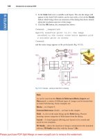
1st Drawing
1st Drawing
cont
cont
•
Pick the GREEN Box
and then click OK
Type “Object”
Click
“Color →
white”
• ENGR-22_Lec-02_ACAD_Intro.ppt
25
Bruce Mayer, PE
Engineering 22 – Engineering Design Graphics
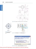
1st Drawing
1st Drawing
cont
cont
•
Set the “Object”
Layer to Current
Double click the
“Status” box
•
Set the “Object” Layer
to Current using
Status box
•
Click OK
6. Use the drawing
Tools to make
some Shapes &
Lines that Fill a
significant Portion
of the screen
5. Hit the Save tool