FIBER REINFORCED HIGH STRENGTH CONCRETE WITH CELLULAR STEEL SANDWICH COMPOSITE PANEL FOR BLAST AND IMPACT MITIGATION
Bạn đang xem bản rút gọn của tài liệu. Xem và tải ngay bản đầy đủ của tài liệu tại đây (9.04 MB, 215 trang )
FIBRE REINFORCED HIGH STRENGTH CONCRETE WITH CELLULAR STEEL
SANDWICH COMPOSITE PANEL FOR BLAST AND IMPACT MITIGATION
ABRAHAM CHRISTIAN
NATIONAL UNIVERSITY OF SINGAPORE
2015
FIBRE REINFORCED HIGH STRENGTH CONCRETE WITH CELLULAR STEEL
SANDWICH COMPOSITE PANEL FOR BLAST AND IMPACT MITIGATION
ABRAHAM CHRISTIAN
(B.Eng.(Hons.), Diponegoro University)
A THESIS SUBMITTED
FOR THE DEGREE OF DOCTOR OF PHILOSOPHY
DEPARTMENT OF CIVIL AND ENVIRONMENTAL ENGINEERING
NATIONAL UNIVERSITY OF SINGAPORE
2015
i
Declaration Page
DECLARATION
I hereby declare that this thesis is my original work, and I have written it in its entirety.
I have duly acknowledged all the sources of information which have been used in the thesis.
This thesis has also not been submitted for any degree in any university previously.
Abraham Christian
February 2015
ii
Acknowledgements
All praise to God, only by His grace this study can be completed.
The author wishes to express his sincere gratitude to his supervisors, Assoc. Prof. Ong Khim
Chye, Gary for his personal commitment, patience, interesting discussion, invaluable
guidance and constructive advices throughout the course of this study.
The author’s heartfelt appreciation is dedicated to Dr. Lado R. Chandra, Dr. Patria
Kusumaningrum and Dr. Satadru Das Adhikary for their contributions and continuous
supports.
Sincere thanks are also extended to the DSTA for providing the funding required for blast
experimental testing.
The kind assistance from all the staff members of the NUS Concrete and Structural
Engineering Laboratory is deeply appreciated. Special thanks go to Mr. Koh, Mr. Ang, Mr.
Ishak, Mr. Stanley and Mr. Kamsan for their continuous support during experimental phase
of the study.
Finally, special thanks and loves go to my parents, brother, sister and friends for the moral
supports and constant love. Thank you for making this study possible and may God bless
all of you.
iii
Table of Contents
Declaration Page i
Acknowledgements ii
Table of Contents iii
Summary viii
List of Tables x
List of Figures xi
List of Symbols xviii
Chapter 1 Introduction 1
Background of the study 1
Literature review 7
Composite panel as an energy absorber 7
Metal sandwich panels 7
Steel-concrete-steel (SCS) sandwich panels 12
Fibre composite panels 14
Steel stud composite panel 18
Multi-material layered composite panel 19
Observations arising from the literature review 20
Objectives and scope of study 22
iv
Thesis structure 24
Chapter 2 Proposed Composite Panel 26
Design criteria 26
Proposed composite panel design 29
Constituent composite sections 30
Steel sandwich core structure design 32
Steel sandwich fabrication techniques 35
Connection details for handling and installation 37
Finalized panel design 37
RC specimen fabrication for performance comparison 38
Material usage and cost comparison 39
Fabrication process 40
Chapter 3 Finite Element Analysis 43
Introduction 43
General parameters of EASP FE model 44
Mesh convergence study 44
Development of EASP model 45
Material Models 47
Strain rate effect 59
Contact model 63
Hourglass 64
Bulk viscosity for dynamic loading case 65
v
Erosion criteria for solid elements 66
Other LS-Dyna keyword 66
Validation of FE model 66
Numerical study on the EASP energy absorption 68
Simulation of three point static bending of EASP and RC panels 72
Simulation of EASP specimens subjected to impact loading 74
Simulation of EASP specimens subjected to blast loading 78
Blast wave loading from cylindrical charges 79
Summary of finite element analyse of EASP specimens 83
Chapter 4 Static Performance of EASP 84
Introduction 84
Composite panel under static loading 84
Specimen details 85
RC specimen fabrication for performance comparison 85
Moment capacity analysis 86
Testing setup and instrumentation 92
Results and discussion 93
Load deflection response 93
Failure mode and cracking behaviour of the concrete layer 95
Steel plate strain data 98
Effect of concrete strength and steel fibre incorporation 100
Comparison to analytical and numerical result 101
vi
Conclusions 108
Chapter 5 Impact Performance of EASP 110
Introduction 110
Impact studies on reinforced concrete and steel-concrete composite panel 111
Failure modes 113
Testing method 115
Specimens 115
Test set-up 117
Results and discussion 119
Crack propagation and final crack pattern 120
Damage in the concrete and steel-sandwich layers 127
Displacement-time history 132
Strain measurement on the steel sandwich interface and distal plates 138
Comparison with numerical results 142
EASP with full core configuration 142
EASP with hollow core configuration 145
Discussion 149
EASP with various concrete materials 149
EASP full core versus hollow core 150
EASP versus RC 151
Conclusions 151
Chapter 6 EASP Blast Resistance 153
vii
Introduction 153
Air blast wave in explosions 153
Composite structure subjected to blast loading 160
Testing method 163
Specimens 163
Experimental set-up 164
Results and discussion 165
Pressure histories 168
Displacement-time history 174
Damage assessment 175
Conclusions 177
Chapter 7 Conclusions and Recommendations 179
Review on completed research 179
Conclusion summary 179
Recommendations for future studies 183
References 185
Appendices 190
Publications 191
viii
Summary
The study investigated the performance of concrete-steel composite panels subjected to
static and dynamic loading. The panel consists of fibre-reinforced high strength concrete
overlaid on top of a specially configured steel sandwich, which function to dissipate the
imparted kinetic energy. The core structure of the steel sandwich resists mostly tensile
forces while absorbing the energy through plastic buckling. The novel composite panel was
assigned the name Energy Absorption Sandwich Panel or EASP. The intention was to use it
as a secondary protection or sacrificial cladding panel in existing buildings to shield critical
structural components against blast.
Experimental testing was done in three phases; three point static bending tests, low-
velocity drop-weight impact tests and close-in cylinder TNT explosion tests. Parametric
studies were carried out utilizing two types of steel sandwich core structure (bended and
straight type) as well as various concrete materials: normal strength concrete (NSC) 60
MPa, high strength concrete (HSC) 110 MPa and fibre reinforced high strength concrete
(FRHSC) 110 MPa. Ordinary reinforced concrete panels of the same geometric dimensions
and tension capacity cast with HSC and FRHSC were also included for benchmarking. The
RC panel was on average about 33% heavier than the EASP.
The response of the EASP against static bending, impact and blast loading was obtained
through experimental tests. The performance assessed by observing the damage to the
constituent concrete and steel sandwich layers, comparing the maximum and residual
deformation and observing the failure modes of the different types of panels. It was found
that under static bending tests, the maximum flexural resistance did not differ much
although the EASP could achieve much higher ductility vis-à-vis the high strength
ix
reinforced concrete panel. Under the drop weight impact tests, the EASP exhibited
improved resistance with reduced damage compared with the RC panels. The better
performance of EASP with FRHSC concrete material is characterized by less residual and
maximum deflection, reduced concrete fragmentation and large reduction in concrete
crack propagation. The EASP in general cast using various concrete types and sandwich
cores were able to withstand 800kg drop weight impact loading at an impact velocity of
6.26 m/s. The similar high strength reinforced concrete panel failed with full projectile
penetration. These demonstrated that EASP performed better and possess higher energy
absorption capacity compared with the RC panel. Last but not least, when subjected to
close-in TNT blast loading, the EASP could withstand blast pressures of up to 50 kg of TNT
at 1m standoff distance (equalized mass from cylinder to spherical charges) with minimum
concrete spalling. It showed that the proposed panel has potential to be used as sacrificial
cladding protective panel to resist close-in blast loading.
Finite element simulation using the LS-Dyna software was used to model various types of
panel when subjected to loading used in the three phase tests. The simulation results could
predict the panels’ response against static and dynamic loading with good accuracy. The
combination of fibre reinforced high strength concrete and steel sandwich structure
demonstrated good potential for use as blast and impact mitigation protective panels with
better weight-performance ratios and enhanced energy absorption properties.
Keywords: steel-concrete composite, drop-weight impact, blast loading, fibre reinforced
high strength concrete, steel sandwich structure, energy absorption
x
List of Tables
Table 1-1 List of bombing incidents (wikipedia.org, 2012) 1
Table 3-1 Details of model simulation for mesh convergence study 45
Table 3-2 Concrete mix design 52
Table 3-3 Concrete fracture energy for various strengths and aggregate size (CEB-FIP
1990)………… 55
Table 3-4 Concrete material properties 57
Table 3-5 Steel material properties 58
Table 3-6 Steel rebar & steel plate material properties 59
Table 4-1 Static test specimen details 85
Table 4-2 Bending resistance calculation table (with
m
) 89
Table 4-3 Bending resistance calculation table (without
m
) 90
Table 4-4 Comparison of analytical, numerical and experimental results 108
Table 5-1 Impact test specimens & loading details 117
Table 6-1 Explosives conversion factor 156
xi
List of Figures
Figure 1-1 Catastrophic failure of Alfred P. Murrah building 3
Figure 1-2 The aftermath of Khobar housing complex bombing 4
Figure 1-3 Transmission of blast load from the secondary barrier 6
Figure 1-4 Sandwich panel typical geometry 8
Figure 1-5 Metal sandwich structures (CEL-Components, 2012) 8
Figure 1-6 Deformed shape for steel sandwich (Guruprasad & Mukherjee, 2000b) 9
Figure 1-7 Alporas aluminium foam structure (AlCarbon Technology company) 10
Figure 1-8 Maximum blast impulse sustained by monolithic beams (Fleck & Deshpande,
2004)……………. 11
Figure 1-9 Bi-Steel SCS panel (TATA-STEEL, 2012) 13
Figure 1-10 Bridged crack in FRHSC (BrightHub-Eng., 2011) 15
Figure 1-11 Steel stud wall construction (before and after blast) 18
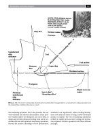
Figure 2-1 Early Design of Energy Absorption Sandwich Panel (EASP) 29
Figure 2-2 Basic principle of the proposed panel 30
Figure 2-3 (a) Typical Structure of SCS; (b) Cellular Sandwich Panel 33
Figure 2-4 Six Types of Steel Sandwich Core Configuration 33
Figure 2-5 Groups of nodes desgnated as fixed support 34
Figure 2-6 Distal Plate Maximum Displacement 34
Figure 2-7 Distal Plate Springback Displacement 35
Figure 2-8 Slot joint design 36
Figure 2-9 Panel connection to supporting structural element 37
Figure 2-10 3D Assembly of easp1 38
xii
Figure 2-11 Rebar details for RC specimen 39
Figure 2-12 Steel Sandwich layer with reinforcing bars 41
Figure 2-13 EASP1 ready for concrete casting (left) and soffit of EASP2 (right) 41
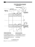
Figure 2-14 Detailed dimensions of EASP1 & EASP2 42
Figure 2-15 CrossS Section of EASP1 & EASP2 42
Figure 3-1 FE model of EASP1 and EASP2 (quarter model) 46
Figure 3-2 Model of alternating welding joint in steel sandwich layer 47
Figure 3-3 (a) Concrete model failure surface and (b) Material model stress-strain
curve…………… 48
Figure 3-4 Concrete mean strength (f
cm
) 52
Figure 3-5 Concrete characteristic strength (f
ck
) 53
Figure 3-6 Single element uniaxial compressive test 53
Figure 3-7 Stress-strain curve of C60 concrete element model 54
Figure 3-8 Stress-strain curve of C110 concrete element model 54
Figure 3-9 Stress-strain curve of C110F concrete element model 55
Figure 3-10 C60 and C110 concrete model tensile stress-strain curve 56
Figure 3-11 Steel coupon stress-strain curve 58
Figure 3-12 Elastic-plastic steel behaviour with kinematic and isotropic hardening 59
Figure 3-13 Stress-strain curves of concrete at different strain rates (T. Ngo, Mendis, P.,
Hongwei, M. & Mak, S., 2004) 60
Figure 3-14 Load-displacement history of RC-C110 specimen in comparison with numerical
prediction…… 67
Figure 3-15 Load-displacement history of RC-C110F specimen in comparison with numerical
prediction…… 67
Figure 3-16 Displacement-time history of FRHSC with 10kg; 0.5m SoD blast. 69
xiii
Figure 3-17 Maximum displacement values of all the panels subjected to various blast
charges: (a) FRHSC; (b) HSC. 70
Figure 3-18 Resistance-deflection curve at 10kg, 0.5m SoD charge of FRHSC materials. 71
Figure 3-19 EASP1 quarter model for static bending simulation 73
Figure 3-20 Numerical load-displacement history EASP1 specimens 73
Figure 3-21 Numerical load-displacement history EASP2 specimens 74
Figure 3-22 Quarter model of the EASP1 specimen for impact simulation 76
Figure 3-23 EASP1 specimens FE simulation results 76
Figure 3-24 EASP2 specimens FE simulation results 77
Figure 3-25 EASP1H specimens FE simulation results 77
Figure 3-26 EASP2H specimens FE simulation results 78
Figure 3-27 Blast pressure prediction for perpendicular charge 80
Figure 3-28 Zone division for applying approximated blast pressure 80
Figure 3-29 EASP1-C110F specimen blast simulation results 81
Figure 3-30 Blast loading approximation for parallel charge 82
Figure 3-31 EASP1-C110 specimen blast simulation results, a comparison 82
Figure 4-1 Rebar details for RC specimen 86
Figure 4-2 Rectangular concrete stress block 86
Figure 4-3 Strain-stress progression from SLS to ULS 87
Figure 4-4 RC compression-tension forces 87
Figure 4-5 EASP1 and EASP2 compression-tension forces 88
Figure 4-6 Moment-curvature curve of EASP2-C60 90
Figure 4-7 Moment-curvature curve of EASP2-C110 91
Figure 4-8 Moment-curvature curve of EASP2-C110F 91
Figure 4-9 Static test setup diagram for EASP specimens 92
Figure 4-10 EASP1 & RC load-displacement history 93
xiv
Figure 4-11 EASP2 & RC load-displacement history 95
Figure 4-12 EASP1 and 2 (C60) specimens crack pattern at Ultimate Load 97
Figure 4-13 EASP1 and 2 (C110) specimens crack pattern at Ultimate Load 97
Figure 4-14 EASP1 and 2 (C110F) specimens crack pattern at Ultimate Load 97
Figure 4-15 RC-C110 and RC-C110F specimens crack pattern at Ultimate Load 97
Figure 4-16 Steel plate strain gauges data 99
Figure 4-17 Crack pattern of (a) RC-C110F and (b) EASP2-C110F 100
Figure 4-18 Load-displacement history and cracking pattern of EASP1-C60 specimen 102
Figure 4-19 Load-displacement history and cracking pattern of EASP1-C110 specimen . 102
Figure 4-20 Load-displacement history and cracking pattern of EASP1-C110F specimen 103
Figure 4-21 Load-displacement history and cracking pattern of EASP2-C60 specimen 103
Figure 4-22 Load-displacement history and cracking pattern of EASP2-C110 specimen . 104
Figure 4-23 Load-displacement history and cracking pattern of EASP2-C110F specimen 105
Figure 4-24 Load-displacement history of RC-C110 specimen 106
Figure 4-25 Load-displacement history of RC-C110F specimen 106
Figure 4-26 Crack propagation of RC-C110F specimen 107
Figure 5-1 J-Hook SCS Sandwich Panel (Liew et al., 2009) 112
Figure 5-2 Deflection profile of various projectile loading rates 113
Figure 5-3 Full core EASP1 (a) and hollow core configuration EASP1H (b) 116
Figure 5-4 Hollow core area of EASP1H (B) compared to EASP1 (a) 116
Figure 5-5 Impact test set-up for EASP specimens 117
Figure 5-6 Impact test experimental set-up for RC specimens 119
Figure 5-7 High speed video footage of EASP1-C60 120
Figure 5-8 High speed video footage of EASP2-C60 121
Figure 5-9 High speed video footage of EASP1-C110 122
Figure 5-10 High speed video footage of EASP1-C110F 123
xv
Figure 5-11 High speed video footage of EASP2-C110F 124
Figure 5-12 High speed video footage of RC-C110 125
Figure 5-13 High speed video footage of RC-C110F 126
Figure 5-14 EASP1 & EASP2 with C60 concrete after impact test 127
Figure 5-15 EASP1 & EASP2 with C110 concrete after impact test 127
Figure 5-16 EASP1 & EASP2 with C110F concrete after impact test 128
Figure 5-17 RC-C110 and RC-C110F specimens after impact test 128
Figure 5-18 EASP1H-C60 after impact test 129
Figure 5-19 EASP2H-C60 crater after the impact 130
Figure 5-20 EASP1H-C110 after impact test 130
Figure 5-21 EASP2H-C110 after impact test 131
Figure 5-22 EASP1H-C110F after impact test 131
Figure 5-23 Displacement time history of EASP2-C60 132
Figure 5-24 Displacement vs Time Graph of EASP1 specimens 134
Figure 5-25 Displacement vs Time graph of EASP2 specimens 134
Figure 5-26 Maximum displacement from image analysis (EASP1-C60) 135
Figure 5-27 Displacement vs Time graph of EASP1H specimens 136
Figure 5-28 Displacement vs Time graph of EASP2H specimens 136
Figure 5-29 EASP 1&2 (C60) strain measurement during 100 ms of impact 138
Figure 5-30 EASP 1&2 (C110) strain measurement during 100 ms of impact 138
Figure 5-31 EASP2-C110F strain measurement during 100 ms of impact 139
Figure 5-32 EASP 1H&2H (C60) strain measurement during 100 ms of impact 139
Figure 5-33 EASP 1H&2H (C110) strain measurement during 100 ms of impact 140
Figure 5-34 EASP 1C&2C (C110F) strain measurement during 100 ms of impact 141
Figure 5-35 Displacement-time history and cracking pattern of EASP1-C60 142
Figure 5-36 Displacement-time history and cracking pattern of EASP1-C110 142
xvi
Figure 5-37 Displacement-time history and cracking pattern of EASP1-C110F 143
Figure 5-38 Displacement-time history and cracking pattern of EASP2-C60 143
Figure 5-39 Displacement-time history and cracking pattern of EASP2-C110 144
Figure 5-40 Displacement-time history and cracking pattern of EASP2-C110F 144
Figure 5-41 Displacement-time history and cracking pattern of EASP1H-C60 145
Figure 5-42 Displacement-time history and cracking pattern of EASP1H-C110 145
Figure 5-43 Displacement-time history and cracking pattern of EASP1H-C110F 146
Figure 5-44 Displacement-time history and cracking pattern of EASP2H-C60 146
Figure 5-45 Displacement-time history and cracking pattern of EASP2H-C110 147
Figure 5-46 Displacement-time history and cracking pattern of EASP2H-C110F 147
Figure 5-47 FE simulation result of RC-C110 specimen 148
Figure 5-48 FE simulation result of RC-C110F specimen 149
Figure 5-49 RC-C110 vs EASP2-C110F after impact 152
Figure 6-1 Blast pressure time history 154
Figure 6-2 Stud to floor anchorage using steel angle 162
Figure 6-3 EASP1 panel 164
Figure 6-4 Blast test set-up of (A) EASP1 C110F and (b) EASP1 C110 165
Figure 6-5 High speed video footage of 5 kg TNT blast with vertical cylinder axis placement
(jetting effect marked) 166
Figure 6-6 High speed video footage of 5 kg TNT blast with horizontal cylinder axis
placement (jetting effect marked) 166
Figure 6-7 EASP1-C110F after blast test (perpendicular charge placement) 167
Figure 6-8 EASP1-C110 after blast test (parallel charge placement) 167
Figure 6-9 5kg TNT Charge (a) perpendicular placement and (b) parallel placement 168
Figure 6-10 Plan view of measurement lines for a cylindrical charge 169
Figure 6-11 Blast angle for (a) perpendicular charge (b) parallel charge 169
xvii
Figure 6-12 Equivalent spherical mass ratio at 22.5° and 0° for a cylindrical TNT 170
Figure 6-13 Blast loading curve for perpendicular charge 171
Figure 6-14 EASP1-C110F specimen blast simulation results 172
Figure 6-15 Equivalent mass ratio at 67.5°, 112.5° and 90° for cylindrical TNT 173
Figure 6-16 Blast loading curve for parallel charge 173
Figure 6-17 Displacement time history of EASP1-C110 specimen 175
Figure 6-18 Failure mode of the EASP1-C110F specimen 176
Figure 6-18 EASP1-C110 specimen blast test result 177
Figure 6-19 EASP1-C110 numerical model 177
xviii
List of Symbols
α
I
Angle of blast incident
Strain rate
s
Quasi static strain rate
c
Concrete strain
s
Steel strain
y
Steel yield strain
max
Maximum principal strain at failure
min
Minimum principal strain at failure
Diameter
m
Partial material safety factor
s
Micro second
d
Dynamic yield stress
s
Static yield stress
u
Ultimate stress
y
Yield stress
a Exponential decay factor for incident wave
A0 Negative of the unconfined concrete strength in MAT72R3
As Steel area
1
b
Compressive damage scaling parameter
2
b
Tensile damage scaling exponent
C Cowper – Symonds strain hardening parameter
C
r
Reflection coefficient
ft
DIF
Dynamic increase factor for tensile strength
'fc
DIF
Dynamic increase factor for compressive strength
E
DIF
Dynamic increase factor for elastic modulus
tan
E
Plastic tangent modulus
c
F
Compression concrete force
xix
sc
F
Compression steel force
st
F
Tension steel force
'
c
f
Uniaxial compressive strength of concrete
co
f
Reference strength of 10 MPa
cd
f
Design strength of concrete
cm
f
Mean strength of concrete
ck
f
Characteristic strength of concrete
fps Frame per second
yd
f
Design strength of steel
y
f
Yield strength of steel
g Gravity
h Height
I Impulse
so
I
Incident impulse
kHz Kilohertz
L Length
cyl
L
Length of cylindrical charge
M Mass
na Neutral axis
P Cowper – Symonds strain hardening parameter
inc
P
Maximum incident pressure
pna Plastic neutral axis
Po Ambient pressure
r
P
Maximum reflected pressure
s
P
Negative under pressure
s
P
Positive overpressure
psi Pounds per square inch
so
P
Ultimate overpressure
Q
x
Mass specific energy for explosives
qs Air velocity
R Structural resistance / standoff distance
xx
cyl
r
Radius of cylindrical charge
sph
r
Radius of spherical charge
R0 Concrete density in MAT72R3
T Natural period of vibration
t Time
t
a
Arrival time
t
d-
Negative phase duration
t
d+
Positive phase duration
V Velocity
t
v
Velocity at t
o
v
Initial velocity
W Charge weight
w/c Water content ratio
x Neutral axis height
Z Scaled distance
Subscripts:
AISI American Iron and Steel Institute
ACI American Concrete Institute
ALE Arbitrary Lagrangian Eulerian
ANFO Ammonium Nitrate-Fuel Oil
BS British Standard
CA Coarse aggregate
CEB Comité Euro-International du Béton
CFOAM Carbon foam
CFRP Carbon Fibre Reinforced Polymer
CL Centre line
CONWEP Conventional weapons effects
DIF Dynamic Increase Factor
DSC Double-skin sandwich construction
DSTA Defence Science & Technology Agency
EAM Energy Absorption Mechanism
EASP Energy Absorption Sandwich Panel
EIFS External insulation and finish system
xxi
ELFORM Element Formulation
EMP Electro-Magnetic Pulse
SS EN Singapore Standard - European Norm
EOS Equation of state
FE Finite element
FIP Fédération Internationale de la Précontrainte
FRHSC Fibre reinforced – high strength concrete
FRP Fibre Reinforced Polymer
GFRP Glass Fibre Reinforced Polymer
HG Hourglass
HRWA High range water-reducing agents
HSC High strength concrete
IED Improvised Explosive Devices
ITZ Interfacial transition zone
LBE Load Blast Enhanced
LSTC Livermore Software Technology Corporation
NRC normal reinforced concrete panels
NSC Normal strength concrete
MIG Metal Inert Gas
MMALE Multi Material Arbitrary Lagrangian Eulerian
NSC Normal Strength Concrete
OPC Ordinary Portland cement
PE Polyethylene
PVC Poly Vinyl Chloride
PAN polyacrylonitrile
RC Reinforced concrete
RMS Root Mean Square
RDX Research Department Explosive
RHSCP Reinforced high strength concrete panel
SCS Steel concrete steel
SDOF Single Degree of Freedom
SF Silica fume
SHPB Split Hopkinson Pressure Bars
SI The International system of units
SLS Serviceability limit states
SP Superplasticizer
xxii
SRA Shrinkage Reduction Admixture
SOD Standoff distance
TNT Tri nitro toluene
UCF Pressure conversion factor
UFC Unified Facilities Criteria
UHPFC Ultra high performance concrete
ULS Ultimate limit states
USA United States of America
VBIED Vehicle Borne Improvised Explosive Devices
WVGA Wide Video Graphic Array
1
Chapter 1 Introduction
Background of the study
In recent years, there have been many incidents of extreme events arising from bomb
explosions ranging from Improvised Explosive Devices (IED) to Vehicle Borne Improvised
Explosive Devices (VBIED). Table 1-1 list several bombing incidents that occurred between
1993 and 2012 which caused damage to buildings and resulted in a large number of human
casualties.
TA B L E 1 - 1 LIS T O F B OMB I N G I N C I D EN T S ( W I KIP E D IA . O R G , 2 0 1 2 )
Date Location Type of attack / bomb used Damage
Bombay, Maharashtra, India 13 car bombs (RDX) with shrapnel 257 killed, 713 injured
Hotels, office, banks great damage to buildings
Oklahoma, USA 3200 kg ammonium nitrate, 168 killed, 680 injured
Alfred P. Murrah Federal Building nitromethane, and tovex 324 buildings destroyed or damaged
Khobar, Saudi Arabia mix of gasoline and explosive powder 20 killed, 372 injured
Khobar Towers housing complex estimated to be equal to 9072 kg TNT destroyed structures
Tanzania & Kenya Truck bomb 223 killed, more than 4000 injured
United States embassies 900 kg of combined explosives nearby buildings collapsed
Moscow, Russia 300-400 kg RDX 94 killed, 249 injured
Apartment on 19 Guryanova Street section of the apartment collapsed
New York City, USA Three large plane with lots of fuel Nearly 3000 killed
World Trade Centre 3 buildings collapsed
Bali, Indonesia Suicide backpack & large car bomb 202 killed, 240 injured
Kuta district potassium chlorate, aluminum powder great damage to buildings
Madrid, Spain IED (improvised explosive device) 191 killed, 2050 injured
Madrid Commuter Train System
Mumbai, India RDX and ammonium nitrate 209 killed, 714 injured
Mumbai Westen Line train combined with pressure cookers
Iraq Car bombs, fuel tanker 796 killed, 1562 injured
Qahtaniya and Jazeera Almost 2 tons of explosives massive damage to buildings
Shah Hasan Khel, Pakistan Suicide bombing 105 killed, 100+ injured
Lakki Marwat district unknown explosives
Sana'a, Yemen Suicide bombing more than 120 killed, 350 injured
Targeted to Yemeni Army parade unknown explosives
July 11, 2006
August 14, 2007
January 1, 2010
May 21, 2012
March 11, 2004
October 12, 2002
March 12, 1993
April 19, 1995
August 7, 1998
September 9, 1999
September 11, 2001
25-Jun-96
Looking at such bombing incidents, a consistent pattern seemed obvious. The attacks were
often targeted at vulnerable buildings with little or no protection against blast. For
example, office and hotel buildings where a single blast could cause severe damage and
result in many casualties. Many of the explosions cause localized damage and lead to