Integration of high k oxides with wide band gap semiconductors
Bạn đang xem bản rút gọn của tài liệu. Xem và tải ngay bản đầy đủ của tài liệu tại đây (3.83 MB, 174 trang )
INTEGRATION OF HIGH-K OXIDES WITH WIDE
BAND-GAP SEMICONDUCTORS
CHEN QIAN
(B. Sc., Chong Qing Univ.)
A THESIS SUBMITTED
FOR THE DEGREE OF DOCTOR OF PHILOSOPHY
DEPARTMENT OF PHYSICS
NATIONAL UNIVERSITY OF SINGAPORE
2011
Acknowledgement
i
Acknowledgement
I would like to express sincere appreciation to my advisor, Prof. Feng Yuanping
from National University of Singapore (NUS) for his strong support and excellent
supervision. He not only taught me many about the research but also shared me his
wisdom, insight, and humor in the last few years. It is really an honor for me to get
the guidance from him.
I would also like to show my sincere appreciation to my advisor, Dr. Wang Shijie
from Institute of Materials Research & Engineering (IMRE) for his guidance,
unwavering support, and encouragement throughout my study. He has constantly
provided me with assistance and valuable advice to improve my research work and
has always been supportive of my research endeavors. I am truly grateful for all the
help and encouragement he has given me during the past four years.
Special thanks to Dr. Chai Jianwei and Wong Ten It for their help in
experiments throughout the years and I have enjoyed all the helpful discussions with
them. They make my Ph.D career a happy memory. Also thanks to other staffs in
IMRE Dr. Pan Jisheng, and Dr. Zhang Zheng for their warm help on my research
work. Thanks to the student at NUS Dr. Yang Ming for his support on my research
work.
I acknowledge National University of Singapore for the research scholarship,
which enables me to conduct my research project and finish this thesis.
Last but not least, I would like to express my deep appreciation to my parents for
their unselfish love and constant support throughout my life. Thanks for their love,
encouragement, and many sacrifices throughout my life, which have made my
education possible.
Table of Context
ii
Table of Contents
Acknowledgement i
Table of Contents ii
Abstract vi
List of Tables ix
List of Figures x
Abbreviation xv
Publications xvii
Chapter 1 Introduction 1
1.1 Wide band-gap semiconductors 1
1.2 High-k dielectrics 5
1.3 The integration of high-k dielectric with wide band-gap semiconductors 11
1.4 Research approaches 14
1.4.1 Nitridation treatment 14
1.4.2 Band offsets at high-k/wide band-gap semiconductor interfaces 15
1.4.3 Electrical properties of HfO
2
gate dielectrics 20
1.5 Objective and significance of the study 24
Chapter 2 Experimental and Computational Methods 27
2.1 Growth techniques 27
2.1.1 High-k dielectrics deposition techniques 27
2.1.2 Metal gates deposition techniques 30
2.1.3 Rapid thermal annealing 31
2.1.4 Nitridation treatment 33
Table of Context
iii
2.2 Characterization techniques 33
2.2.1 X-ray Photoelectron Spectroscopy (XPS) 33
2.2.1.1 Basic principles of XPS 34
2.2.1.2 Important parameters of XPS 35
2.2.1.3 Data interpretation 37
2.2.1.4 Instrument and application of XPS 41
2.2.2 Other characterization techniques 43
2.3 Computational method (First-principles calculations) 46
Chapter 3 High-k dielectrics/SiC interfaces 52
3.1 Introduction 52
3.2 Surface treatment of SiC substrates 53
3.3 Interfacial characterization of HfO
2
gate dielectric on SiC 58
3.3.1 Band alignment at HfO
2
/4H-SiC interfaces 59
3.3.2 Nitridation of HfO
2
film and its thermal stability 60
3.3.3 Interface properties of HfO
2
/6H-SiC stacks and its thermal stability 64
3.3.4 First-principle calculation of electronic structure of nitrogen-doped HfO
2
films 66
3.4 Electrical characterization of Ni/HfO
2
/SiC MOS capacitors 69
3.4.1 MOS fabrication process and measurement setup 69
3.4.2 Frequency dependence of electrical properties 70
3.4.3 Rapid thermal annealing effect on the electric properties 73
3.4.4 Conduction mechanisms in high-k gate dielectrics 74
3.5 Interface characterization of HfO
2
dielectric on graphene formed on SiC 79
3.5.1 Growth and electronic properties of graphene on SiC 80
3.5.2 Growth and band alignment of HfO
2
dielectric on graphene and its thermal
stability 82
Table of Context
iv
3.6 Summary 87
Chapter 4 High-k dielectrics/GaN interfaces 89
4.1 Introduction 89
4.2 Surface passivation of GaN 90
4.3 Interface characterization of HfO
2
/GaN stacks 93
4.3.1 Band alignment at HfO
2
/GaN interfaces 93
4.3.2 Post-thermal annealing 99
4.4 Electrical characterization of Ni/HfO
2
/GaN MOS capacitors 100
4.4.1 MOS fabrication process and measurement setup 101
4.4.2 Frequency dependence of electrical properties 102
4.4.3 Rapid thermal annealing effect on the electric properties 106
4.4.4 Current conduction mechanism 108
4.5 Summary 109
Chapter 5 High-k dielectrics/ZnO interfaces 110
5.1 Introduction 110
5.2 Interface characterization of HfO
2
/ZnO stacks 111
5.2.1 Band alignment at HfO
2
/ZnO interfaces 112
5.2.2 First-principle calculation on the structure and properties of HfO
2
/ZnO
interfaces 115
5.3 Interfaces characterization of ZrO
2
/ZnO stacks 119
5.3.1 Epitaxial relationship of ZrO
2
/ZnO heterostructure 120
5.3.2 Band alignment at ZrO
2
/ZnO interfaces 122
5.3.3 First-principle calculation of electronic structure of ZrO
2
/ZnO interfaces
124
5.4 Thermal stability and band alignment of N-doped ZnO 126
Table of Context
v
5.4.1 Nitridation treatment of ZnO and its thermal stability 126
5.4.2 First-principle calculation of electronic structure of N-doped ZnO 130
5.5 Summary 133
Chapter 6 Conclusion and future works 135
6.1 Conclusion 135
6.2 Future works 139
References………………………………………………………………… …………….141
Abstract
vi
Abstract
Silicon-based Metal-oxide-semiconductor field effect transistors (MOSFET)
devices have been thrust of research over the years and are the most developed.
However, recent development has allowed silicon system technology to approach the
theoretical limits, such as higher blocking voltage, switching frequency and large gate
leakage current. To overcome these limitations, during the past several years, a new
group of materials has emerged as candidates to replace silicon in the near future,
which has enabled applications from optoelectronics devices to high-power, high-
temperature, and high-frequency microelectronic devices. This group is known as the
wide band-gap semiconductors (WBGs), and is led by SiC, ZnO and GaN. These
large band-gap materials allow commercialization in power MOSFET devices, where
Si cannot be used. Besides the recent progress of wide band-gap semiconductor to
replace silicon in MOSFET devices, high-k oxides have been proposed as alternatives
to replace conventional silicon dioxide in MOS devices. It is clear that the dielectric
layer downscaling in MOSFET device is limited by the leakage current problem and it
is an urgent task to introduce new dielectric material with higher dielectric constant
(high-k) to replace silicon dioxide as the gate dielectrics. Therefore, in this thesis,
integration of high-k dielectric materials with wide band-gap semiconductors was
studied by using both experimental and theoretical methods.
The growth and characterization (e.g. electronic structure, thermal stability) of
HfO
2
films on various wide band-gap semiconductor substrates (SiC, GaN and ZnO)
were studied by in situ x-ray photoelectron spectroscopy (XPS). The band alignment
at the HfO
2
/WBGs interface was accurately measured by XPS using a core-level
based method. The sufficiently large band offsets between HfO
2
films and various
Abstract
vii
wide band-gap semiconductor substrates (SiC, GaN and ZnO) indicate that HfO
2
dielectric is a promising candidate to be integrated with various wide band-gap
semiconductors in the downscaling of MOSFET devices. The effects of interfacial
structure on the band alignments and thermal stabilities of HfO
2
films on SiC, GaN
and ZnO substrates were also studied. It was found that the interfacial layer changed
the band alignments by modifying the interfacial dipoles, which indicates that it is
essential to understand and control the interfacial structure to improve the device
performance.
Ni was chosen as a prototype of metal gates to be grown on HfO
2
to fabricate the
Ni/HfO
2
/WBGs MOS capacitors. The capacitance and current properties responding
to the variation of bias voltage of Ni/HfO
2
/WBGs MOS gate stacks in comparison
with these of gate stacks after rapid thermal process (RTP) in nitrogen and oxygen
ambient was investigated. It can be seen that the RTP can effectively reduce oxygen
vacancies in the as-deposited HfO
2
films. As a result, interface quality of HfO
2
/WBGs
after RTP was improved.
The effect of nitridation on the electronic structures and thermal stabilities of
high-k dielectrics films (HfO
2
) was studied by using in situ x-ray photoelectron
spectroscopy (XPS) and First-principles calculations. It was found that nitrogen
doping not only can passivate the oxygen vacancies in high-k dielectrics films, but
also can change the electronic structure of high-k dielectric films. This work suggests
that the nitridation process should be well-controlled to optimize the performance of
high-k dielectric films.
The research of such integration of high dielectric oxide films on wide band-gap
semiconductors by the combination of experimental and theoretical methods is very
Abstract
viii
important not only for the fundamental research, but also in the field of semiconductor
nanoelectronics device manufacture.
List of Tables
ix
List of Tables
Table 1.1 Physical and electronic properties of WBGs compared with Si 3
List of Figures
x
List of Figures
Chapter 1
Figure 1.1 Historical trend of transistor scaling agrees with the Moore’s Law 8
Figure 1.2 Schematic of high-k gate oxide replace the SiO
2
in MOS device 9
Figure 1.3 Schematic of band offsets determining carrier injection in oxide band
states 13
Figure 1.4 Energy band diagram for illustrating the core-level based XPS method to
investigate the band offsets at high-k dielectrics/WBGs interfaces. 16
Figure 1.5 C-V measurement circuit for MOS capacitor structure 21
Figure 1.6 Energy-band diagrams of an ideal MIS capacitor with a p-type
semiconductor at V
G
≠ 0 for (a) accumulation, (b) depletion, and (c) inversion
conditions 22
Chapter 2
Figure 2.1 Schematic Pulsed Laser Deposition (PLD) system. 28
Figure 2.2 Schematic illustration of a RF sputtering chamber 29
Figure 2.3 Schematic Omicron EFM3 e-Beam evaporator system 31
Figure 2.4 Schematic diagram of a rapid thermal processing system. 32
Figure 2.5 Schematic photoemission process of XPS 34
Figure 2.6 Schematic XPS measurement. 42
Figure 2.7 Main components of VG ESCA LAB-220i XL XPS system. 43
Figure 2.8 X-ray diffraction (XRD) θ-2θ scan. 44
Chapter 3
Figure 3.1 Si 2p spectra for a clean SiC surface and for SiC surfaces after nitridation
at RT 55
Figure 3.2 N 1s spectra for 4H-SiC samples after nitridation at room temperatures
and N 1s spectra obtained from SiC surfaces annealed at different temperatures after
nitridation at RT 57
Figure 3.3 C 1s spectra for clean SiC surface, C-rich SiC surface, and C-rich surface
after nitridation at RT 58
List of Figures
xi
Figure 3.4 (a) Core level Si 2p and valence-band spectra of clean 4H-SiC and pure
HfO
2
grown on 4H-SiC (b) the energy-band alignments for pure HfO
2
grown on 4H-
SiC 59
Figure 3.5 Valence-band spectra of pure HfO
2
grown on 4H-SiC and HfO
2
:N grown
on 4H-SiC at RT 61
Figure 3.6 Core level XPS spectra (a) Hf 4f, (b) O 1s, (c) N 1s of as-grown, nitrided
HfO
2
grown on 4H-SiC at RT and nitrided HfO
2
grown on 4H-SiC after annealing at
300
o
C, 400
o
C and 500
o
C 62
Figure 3.7 Valence-band spectra of nitrided HfO
2
film grown on 4H-SiC after
annealing at 300
o
C, 400
o
C and 500
o
C 64
Figure 3.8 The valence band and Si 2p photoelectron spectra of (a) clean 6H-SiC
substrate, (b) pure HfO
2
grown on 6H-SiC, (c) nitrided HfO
2
/6H-SiC at RT, and
nitrided HfO
2
/6H-SiC
after annealing at 300
o
C (d), 400
o
C (e) and 500
o
C (f). 65
Figure 3.9 Density of states of (a) pure HfO
2
, (b) HfO
x
with O vacancy, (c) HfO
2
with nitridation, (d) HfO
2
with nitridation and O interstitial, and (f) HfO
2
with N
interstitial. 68
Figure 3.10 (a) Capacitance-voltage (C-V) curves of Ni/HfO
2
/SiC MOS capacitors (b)
hysteresis characteristics of Ni/HfO
2
/SiC gate stacks at 100 kHz 71
Figure 3.11 C-V characteristics of Ni/HfO
2
/SiC MOS capacitor with simulated C-V
curve 72
Figure 3.12 C-V characteristics of Ni/HfO
2
/SiC MOS capacitor after (a) N
2
RTP and
(b) O
2
RTP with simulated C-V curves 73
Figure 3.13 Leakage current characteristics of as-deposited, N
2
and O
2
RTP HfO
2
gate stacks. 74
Figure 3.14 Leakage current density of HfO
2
gate dielectrics with EOT 2.4 nm. 76
Figure 3.15 The conduction mechanism in HfO
2
gate dielectrics with EOT 2.4 nm
The straight line is a linear scale. (a) Schottky emission; (b) Poole-Frenkel emission;
(c) Fowler-Nordheim tunneling 78
Figure 3.16 High resolution 100×100 nm
2
and 10×10 nm
2
STM image of epitaxial
graphene grown on 4H-SiC(0001) substrate 80
List of Figures
xii
Figure 3.17 C 1s core-level spectra for the epitaxial graphene on 4H-SiC(0001)
measured at photoelectron take-off angles of 30
o
and 90
o
, respectively, with respect to
the sample surface. 81
Figure 3.18 XPS spectra of C 1s and Hf 4f for the (a) as-deposited, (b) oxidized Hf
on graphene/4H-SiC(0001), and (c) thin HfO
2
film on graphene/4H-SiC(0001) after
annealing at 650
o
C. 82
Figure 3.19 Schematic energy diagram for interfacial charge transfer process 84
Figure 3.20 The valence-band and Si 2p photoelectron spectra of (a) pretreatment
annealed graphene/4H-SiC(0001) at 500
o
C, (b) as-deposited, (c) oxidized Hf on
graphene/4H-SiC(0001), and (d) thin HfO
2
film on graphene/4H-SiC(0001) after
annealing at 650
o
C. 85
Chapter 4
Figure 4.1 The valence band and core level Ga 3d photoelectron spectra of (a) as-
grown and surface cleaned n-type GaN (b) as-grown and surface cleaned p-type GaN .
91
Figure 4.2 Schematics of the band diagram of the as-grown GaN surface and surface
bombarded with nitrogen plasma. 92
Figure 4.3 The Ga 3d and Hf 4f core level and valence band spectra of bare n-type
GaN, a thin HfO
2
film grown on n-type GaN substrate and a thick HfO
2
film on n-
type GaN substrate. 94
Figure 4.4 The core level Ga 3d and Hf 4f and valence band spectra of bare p-type
GaN, a thin HfO
2
film grown on p-type GaN substrate and a thick HfO
2
film on p-
type GaN substrate. 97
Figure 4.5 Energy-band alignment for HfO
2
grown on n-type and p-type GaN 99
Figure 4.6 The Ga 3d and Hf 4f core level and valence band spectra of (a) HfO
2
/n-
GaN and (b) HfO
2
/p-GaN after annealing at 700
o
C. 100
Figure 4.7 Capacitance-voltage (C-V) curves of Ni/HfO
2
/n-GaN MOS capacitors 102
Figure 4.8 (a) Hysteresis characteristics of Ni/HfO
2
/n-GaN gate stacks at 100 kHz (b)
C-V characteristics of Ni/HfO
2
/n-GaN MOS capacitor with simulated C-V curve 104
List of Figures
xiii
Figure 4.9 (a) Capacitance-voltage(C-V) curves of Ni/HfO
2
/p-GaN MOS capacitors
with simulated C-V curve (b) hysteresis characteristics of Ni/HfO
2
/p-GaN gate stacks
at 100 kHz. 105
Figure 4.10 C-V characteristics of Ni/HfO
2
/n-GaN MOS capacitor after (a) N
2
RTP
and (b) O
2
RTP 106
Figure 4.11 C-V characteristics of Ni/HfO
2
/p-GaN MOS capacitor after (a) N
2
RTP
and (b) O
2
RTP 107
Figure 4.12 Leakage current characteristics of as-deposited, N
2
and O
2
RTP HfO
2
gate stacks on (a) n-type GaN and (b) p-type GaN 108
Chapter 5
Figure 5.1 The valence band and Zn 3d photoelectron spectra of (a) bare ZnO (0001)
substrate (b) 40 Å HfO
2
film grown on ZnO (0001) substrate, and (c) thick HfO
2
film
on ZnO (0001) substrate. 114
Figure 5.2 Energy-band alignment for HfO
2
grown ZnO 115
Figure 5.3 Interface model for HfO
2
/ZnO(0001). Blue atoms are Hf, red atoms are O
and gray atoms are Zn 117
Figure 5.4 Density of states of bulk ZnO (0001) and HfO
2
/ZnO (0001) 118
Figure 5.5 Six interface model for HfO
2
/ZnO(0001). Blue atoms are Hf, red atoms
are O and gray atoms are Zn 119
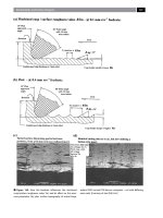
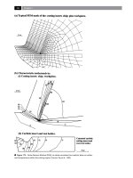
Figure 5.6 (a) Out-of-plane XRD pattern of epitaxial ZnO on YSZ (111), (b) in-plan
XRD pattern of epitaxial ZnO on YSZ (111), and (c) schematic orientation
relationship of ZnO (0001) on YSZ (111). 121
Figure 5.7 Core-level and valence band photoelectron spectra for (a) single crystal
ZnO (0001) surface, (b) 50 Å epitaxial YSZ on ZnO (0001), and (c) thick 200 Å
epitaxial YSZ film on ZnO (0001) surface 123
Figure 5.8 (a) Schematic atom configuration at ZnO (0001)//ZrO
2
(111) interface; (b)
PDOS of the oxygen atoms from the bulk-like ZnO and ZrO
2
regions in the model.
125
Figure 5.9 (a) The valence band and Zn 3d photoelectron spectra of as-received ZnO
film, ZnO:N at RT, and nitrided ZnO after annealing at 300
o
C,400
o
C and 500
o
C
List of Figures
xiv
(b)The zoom in valence band photoelectron spectra of as-received ZnO film, ZnO:N
at RT, and nitrided ZnO after annealing at 300
o
C, 400
o
C and 500
o
C 128
Figure 5.10 N 1s of nitrided ZnO at RT and nitrided ZnO after annealing at 300
o
C,
400
o
C and 500
o
C 130
Figure 5.11 Density of states of (a) pure ZnO, (b) ZnO with O vacancy, (c) ZnO with
nitridation, (d) ZnO with nitridation and O interstitial, and (e) ZnO with N interstitial.
Black lines indicate the total density of states for the models: red, green and cyan lines
indicate the atomic site-projected density of states for oxygen atoms in bulk-like
region, nitrogen atoms and zinc atom respectively. 133
Abbreviations
xv
Abbreviations
ALD Atomic layer deposition
BE Binding energy
CBO Conduction band offset
C
ox
Oxide capacitance
CNL Charge neutrality level
CVD Chemical vapor deposition
CASTEP Cambridge serial total energy package
D
it
Interface density of traps
DFT Density functional theory
DOS Density of states
EOT Equivalent oxide thickness
EA Electron affinity
FWHM Full width at half maximum
GGA Generalized-gradient approximation
High-k High dielectric constant
HEMTs High electron mobility transistors
IC Integrated circuits
ITRS International technology roadmap for semiconductors
LDA Local density approximation
LED Light emitting diode
MOSFETs Metal-oxide-semiconductor-field effect transistors
MBE Molecular beam epitaxy
MIGS Metal induced gap states
PDOS Atomprojected density of states
PVD Physical vapor deposition
PLD Pulsed laser deposition
RTP Rapid thermal process
RTA Rapid thermal anneal
RT Room temperature
RF Radio frequency
Abbreviations
xvi
STM Scanning tunneling microscope
SCCM Standard cubic centimeters per minute
TFT Transparent thin film transistor
UHV Ultra-high vacuum
VBO Valence band offset
VBM Valence-band maximum
VASP Vienna ab-initio simulation package
WBGs Wide band-gap semiconductors
WF Work function
XPS X-ray photoelectron spectroscopy
XRD X-ray diffraction
YSZ Yttrium-stabilized ZrO
2
Publications
xvii
Publications
1. Q. Chen, Y. P. Feng, J. W. Chai, Z. Zhang, J. S. Pan and S. J. Wang “Band
alignment and thermal stability of HfO
2
gate dielectric on SiC” Applied Physics
Letters, Vol. 93, 052104 (2008)
2. Q. Chen, M. Yang, Y. P. Feng, J. W. Chai, Z. Zhang, J. S. Pan and S. J. Wang
“Band offsets of HfO
2
/ZnO interface: In situ X-ray photoelectron spectroscopy
measurement and ab initio calculation” Applied Physics Letters, Vol. 95,
162104(2009)
3. Q. Chen, H. Huang, W. Chen , A. T. S. Wee , Y. P. Feng , J. W. Chai , Z. Zhang , J.
S. Pan and S. J. Wang “In situ photoemission spectroscopy study on formation of
HfO
2
dielectrics on epitaxial graphene on SiC substrate” Applied Physics Letters,
Vol. 96, 072111(2010)
4. Q. Chen, Y. P. Feng, J. W. Chai, Z. Zhang, J. S. Pan and S. J. Wang “In situ X-ray
photoelectron spectroscopy studies of HfO
2
gate dielectric on SiC” Thin Solid
Films, 518 e31(2010)
5. M. Yang, R. Q. Wu, Q. Chen, W. S. Deng, Y. P. Feng, J. W. Chai, J. S. Pan, S. J.
Wang “Impact of oxide defects on band offset at GeO
2
/Ge interface” Applied
Physics Letters, Vol. 94, 142903(2009)
6. J. W. Chai, Z. Zhang, J. S. Pan, S. J. Wang, Q. Chen and C. H. A. Huan “X-ray
photoelectron spectroscop studies of nitridation on 4H-SiC(0001) surface by direct
nitrogen atomic source” Applied Physics Letters, Vol. 92, 092119(2008)
7. M. Yang, G. W. Peng, R. Q. Wu, W. S. Deng, L. Shen, Q. Chen, Y. P. Feng, J. W.
Chai, J. S. Pan, S. J. Wang, “Interface properties of Ge
3
N
4
/Ge(111): Ab initio and
x-ray photoemission spectroscopy study” Applied Physics Letters, Vol. 93,
222907(2008)
8. S. J. Wang, T. I. Wong, Q. Chen, M. Yang, L. M. Wong, J.W. Chai, Z. Zhang, J. S.
Pan and Y. P. Feng “Atomic and electronic structures at ZnO and ZrO
2
interface for
transparent thin-film transistors” Phys. Status Solidi A, 207, 1731(2010)
9. M. Yang, W. S. Deng, Q. Chen, Y. P. Feng, S. J. Wang et al “Band alignments at
SrZrO
3
/Ge(001) interface: Thermal annealing effects” Applied Surface Science, 256,
4850(2010)
10. Q. Chen, Y. P. Feng, J. W. Chai, Z. Zhang, J. S. Pan and S. J. Wang
“Photoemission spectroscopy study on the energy-band alignment of n- and p-type
GaN/HfO
2
interfaces”, to be submitted.
11. Q. Chen, Y. P. Feng, J. W. Chai, Z. Zhang, J. S. Pan and S. J. Wang “Electrical
characteristics of n- and p- type GaN-based metal-oxide-semiconductor capacitors
with sputtered HfO
2
gate dielectrics”, to be submitted.
12. Q. Chen, Y. P. Feng, J. W. Chai, Z. Zhang, J. S. Pan and S. J. Wang “Thermal
stability and band alignment of N-doped ZnO: x-ray Photoemission spectroscopy
and first-principles studies”, to be submitted.
Chapter 1 Introduction
1
1. Chapter One
Introduction
1.1 Wide band-gap semiconductors
During the past 50 years, the development of microelectronic technology,
especially the invention of transistors and their integration into silicon integration
circuits, has been a driving force in many aspects of human advancement. Evolution
from the simple transistor to complex semiconductor devices created today has
allowed the realization of semiconductor industry to be the high-technology resource.
The semiconductor industry has developed so fast that various electronic equipments
based on semiconductor devices with high performance and low cost have become an
important part of our lives. Silicon-based devices have been a thrust of research over
the years and become the most developed, but conventional semiconductor material
(silicon) is no longer satisfying people’s high demand for the recent development of
advances. Because silicon semiconductor technology has approached the theoretical
limits, such as switching frequency, operating temperature, breakdown voltage,
efficiency and reliability, it is very important to explore and study new semiconductor
materials with superior properties.
Need wide band-gap semiconductors
To overcome the limitations due to the intrinsic properties of silicon, during the
past several years, a new group of materials has emerged as candidates to replace Si in
the near future, which has enabled applications from optoelectronics devices to high-
power, high-temperature, and high-frequency microelectronic devices. This group is
Chapter 1 Introduction
2
known as the wide band-gap semiconductors (WBGs), and is lead by silicon carbide
(SiC), zinc oxide (ZnO) and gallium nitride (GaN) with electronic band gaps larger
than two electronvolts (eV). Compared with Si, WBGs (SiC, GaN and ZnO) exhibit
inherent excellent properties such as larger band-gap, higher electron mobility and
higher breakdown field strength as shown in Table 1.1. For example, the breakdown
electric field strengths of SiC, GaN and ZnO (3.2, 3, 2 MV/cm) are much higher than
that of Si (0.3 MV/cm). This type of breakdown is obviously referred to catastrophic
breakdown. This property determines how high the electrical field in the material can
be before material breakdown occurs and makes wide band-gap semiconductors
attractive for high-power applications that require large electric fields. The saturated
drift velocities of SiC, GaN and ZnO are double that of Si (1 vs 2×10
-7
cm/sec), and
this means that the channel current can be obtained as high as possible for
microelectronic devices. Furthermore, the much wider band-gap of WBGs compared
with that of Si indicates that the probability of thermal excitation of carriers from the
valence band to conduction is reduced significantly by the large band-gap, and it is
beneficial for high temperature application. Besides, high-purity SiC material has the
highest reported thermal conductivity which is more than three times higher than that
of Si (1.5 vs 4.9 W/cm-K). It is often quoted that the thermal conductivity of SiC is
higher than that of copper at room temperature. An increase in temperature generally
leads to a change in the physical properties of the device, which normally affects the
device in a negative way. An example is the carrier mobility, which decreases with
the increasing temperature. Heat generated through various resistive losses during
operation, therefore must be removed from the device and into the package.
Chapter 1 Introduction
3
Table 1.1 Physical and electronic properties of WBGs compared with Si
1-7
Property
Si
4H-SiC
6H-
SiC
GaN
ZnO
Lattice constants a&c (Å)
3.08&1.89
3.12&5.18
3.25&5.2
Band-gap, Eg (eV)
1.12
3.25
3.03
3.4
3.37
Electric breakdown field,
Ec (MV/cm)
0.3
3.2
2.5
>3
~2
Thermal conductivity, λ
(W/cm·K)
1.5
4.9
4.9
1.3-1.7
1.35-1.47
Saturated electron drift
velocity, V
sat
(×10
7
cm/s)
1
2
2
2.2
2
Thus, these large band-gap materials with their superior characteristics allow for
applications in environments such as pressure vessels, combustion engines and near
nuclear reactors, where Si and GaAs cannot be used.
SiC: The industry application of SiC began with the blue light emitting diode (LED),
which was very weak due to the indirect bandgap of SiC but was the only commercial
blue electroluminescent light source in the late 1980s. Today high-frequency metal-
oxide-semiconductor-field effect transistors (MOSFET) are commercially available
and a market for Schottky diodes made from SiC is emerging. We are still at the
beginning of the SiC revolution, however, and the material’s full potential is not yet to
be realized.
The basic building block of a silicon carbide crystal is a pair of Si and C atoms,
and each Si atom is located at the center of tetrahedron with four carbon atoms at the
corners. Four carbon atoms are covalently bonded with a silicon atom in the center.
The polymorphism of SiC is characterized by a large family of similar crystalline
structures called polytypes. All polytypes have a hexagonal frame of SiC bilayers.
They are variations of the same chemical compound that are identical in two
Chapter 1 Introduction
4
dimensions and differ from the third one. Thus, they can be viewed as layers stacked
in a certain sequence. More than 200 different polytypes of SiC exist depending on
the repetition period of SiC bilayers. The two important polytypes, 6H-SiC and 4H-
SiC (H for hexagonal, the number in the notation determines the number of layers
before the sequence repeats itself) are most intensively studied in the past.
GaN: The growth of GaN dates back to the early 1940’s, when ammonia was passed
over hot gallium, resulting in GaN needles.
8
In the 1960’s small poly-crystals of GaN
were produced that were useful for basic studies of the physical and electronic
properties. In 1969 single crystal GaN thin films were obtained by vapor phase
growth as reported by Maruska and Tietjen.
9
The availability of thin films led to an
increase in GaN-related research in film growth and device development. In 1988,
Amano and Akasaki
10
established a technique for growing p-type GaN, using Mg as
the acceptor impurity.
The earliest gallium nitride-based metal-oxide-semiconductor field effect
transistors were experimentally demonstrated in 1993 and they are being actively
developed.
ZnO: Zinc oxide has already been investigated in 1912. With the beginning of the
semiconductor age after the invention of the transistor,
11
systematic investigations of
ZnO as a compound semiconductor were performed. Currently, research on zinc
oxide as a semiconducting material is starting a renaissance after intensive research
periods in the 1950s and 1970s.
12-13
The results of these earlier activities were
summarized in reviews by Heiland, Mollwo and Stockmann,
14
Hirschwald,
15
and
Klingshirn and Haug
16
. Since about 1990 an enormous increase of the number of
Chapter 1 Introduction
5
publications on ZnO occurred and more recent reviews on ZnO have been
published.
17
Zinc oxide crystallizes in three forms: hexagonal wurtzite, cubic zincblende, and
the rarely observed cubic rocksalt. The wurtzite structure is most stable at ambient
conditions and thus most common. The zincblende form can be stabilized by growing
ZnO on substrates with cubic lattice structure. In both cases, the zinc and oxide
centers are tetrahedral. The rocksalt (NaCl-type) structure is only observed at
relatively high pressures about 10 Gpa.
ZnO has numerous attractive characteristics for electronic and optoelectronic
devices. It has direct band-gap energy of 3.37 eV, which makes it transparent in
visible light and operates in the UV to blue wavelengths. The exciton binding energy
is about 60meV for ZnO. The higher exciton binding energy enhances the
luminescence efficiency of light emission. ZnO can be grown on inexpensive
substrate, such as glass, at relatively low temperatures.
Besides the recent progress of wide band-gap semiconductor to replace silicon in
MOSFET devices, it is necessary to consider whether the traditional gate oxide
(silicon dioxide) is suitable for the integration with the wide band-gap semiconductors
any more. In the next section, the advantages of using high dielectric constant (high-k)
materials rather than silicon dioxide as the gate oxide in WBGs-based MOS devices
and the relevant issues will be introduced.
1.2 High-k dielectrics
The limitations imposed by SiO
2
prompt search for high-k oxides as alternatives to
replace conventional silicon dioxide in the MOS devices. The two reasons for the
Chapter 1 Introduction
6
high-k gate dielectrics to replace silicon dioxide in MOS devices will be discussed in
the following:
(1) Electric field: The electric field across an interface of gate oxide and wide band-
gap semiconductor (WBG) scales inversely with the dielectric constant of the material.
According to the Gauss’s law at the interface:
(1.1)
the electric field in wide band-gap semiconductor is restricted due to the low
dielectric constant of SiO
2
(k=3.9). If we take one of the wide band-gap
semiconductors SiC as an example, the low dielectric constant of SiO
2
(k=3.9) relative
to that of SiC (k=10) results in an electric field in SiO
2
is 2.5 times higher than that in
SiC. This inequity requires device operation at a substrate electric field far below the
wide band-gap semiconductor breakdown field to avoid premature SiO
2
breakdown.
Thus the high breakdown field of wide band-gap semiconductor is severely
underutilized, minimizing one of the material’s major advantages for high-power
applications. Since the blocking voltage of the power MOS devices scales with the
square of the electric field, the device’s blocking voltage capability is dramatically
reduced for a given on-resistance. Therefore, the relatively thick high-k gate
dielectrics have been expected to replace SiO
2
to enable MOS devices operation near
WBGs breakdown field while maintaining a significantly lower field in the oxide.
(2) MOSFET scaling: In the past forty years, the rapid progress of semiconductor
industry has been witnessed in productivity and performance. This improvement is
primarily achieved by means of the MOSFET continually down scaling in size to ever
smaller dimensions. Smaller MOSFETs are desirable for several reasons. One reason
is to pack more devices in a given chip area. This results in a chip with the same
Chapter 1 Introduction
7
functionality in a smaller area, or chips with more functionality in the same area. The
cost per integrated circuits (IC) is mainly related to the number of chips that can be
produced per wafer. Hence, smaller IC allow more chips per wafer, reducing the price
per chip.
Another reason is that high performance of MOS device is determined by large
drive current that flows from source to drain, because the drive current is related to
the switch time of the MOS devices. Since the drive current is controlled by the
electric field across the channel/insulating gate oxide interfaces produced by applying
a voltage to the gate electrode. The strength of the electric field (hence the speed of
transistors) is determined by the applied voltage, the thickness and the dielectric
constants of gate oxides.
18
Higher speed of transistors can be achieved by the
downscaling of transistors, which have stimulated the semiconductor industry to
further shrink the transistors sizes.
The scaling of semiconductor devices follows the famous Moore’s law,
19
which
predicted that the number of transistors in an integrated circuit roughly doubles every
18 months, resulting in higher performance and lower cost.
20
The physical gate length
and technology node of transistor has been reduced to lower than 30 nm and 65nm
separately since the 2000, as shown in Figure 1.1. According to the latest International
Technology Roadmap for semiconductors (ITRS), the next generation of Si-based
MOSFETs will require gate dielectrics layer with the thicknesses around 1 nm, both
for the high performance logic application and low operation power logic applications.