thuyết minh biên pháp thi công cọc khoan nhồi metro HCM method bored pile onland REV.B English
Bạn đang xem bản rút gọn của tài liệu. Xem và tải ngay bản đầy đủ của tài liệu tại đây (1.49 MB, 32 trang )
HCMC Metro Cp-2 Project
TITLE :
Method Statement of
Bored Pile Construction
On Land
Ho Chi Minh City Urban Railway Construction Project
PROJECT TITLE:
Ben Thanh - Suoi Tien Section (Line 1)
Construction Package 2 : Civil (Elevated & Depot)
Method Statement of Bored Pile Construction on
Land
REVISION STATUS
REV. No.
DATE
B
19th Feb. 2013
DESCRIPTION
SECOND ISSUE
PREPARED BY
NAME
SIGNATURE
DATE
REMARKS
CHECKED BY
APPROVED BY
HCMC Metro Cp-2 Project
TITLE :
Method Statement of
Bored Pile
Construction On Land
TABLE OF CONTENTS
1
INTRODUCTION.......................................................................................................3
0.1 OVERALL OF PROJECT .......................................................................................3
0.2 GENERAL ..............................................................................................................3
0.3 WORK SCOPE........................................................................................................3
1 CONSTRUCTION PROCEDURE...................................................................................4
1.1 WORK FLOW-CHART.............................................................................................4
1.2 WORK PROCEDURE..............................................................................................6
(1) Preparation Works................................................................................................6
(2) Setting center point of the bored piles.................................................................7
(3) Assembling Guide frame......................................................................................8
(4) Setting of the temporary casing...........................................................................8
(5) Drilling work..........................................................................................................9
(6) 1st Cleaning bottom of the holes & Changinh Bentonite...................................12
(7) Fabrication and Installation of the rebar cage....................................................13
(8) Setting of Tremie Pipe and Re-cleaning (2nd Time Clearing) of Bored hole.....15
(9) Casting concrete................................................................................................16
(10) Removal of Temporary Casing.........................................................................18
2 RESOURCES TO BE USED........................................................................................18
3.1 EQUIPMENT TO BE USED...............................................................................18
* The equipment (type and quantity) might be changed depending on the site
situation. ......................................................................................................................19
3.2 ORGANIZATION....................................................................................................20
2.1 RESPONSIBILITY OF STAFF...............................................................................20
3 CONTINGENCY AND SOLUTION...............................................................................21
3.1 CONTINGENCY OF DRILLING WORK................................................................21
3.2 CONTINGENCY OF SUCCESSIVE WORK..........................................................22
4 GROUND MOVEMENT AND SOLUTION....................................................................22
4.1 GROUND MOVEMENT.........................................................................................22
4.2 SOLUTION.............................................................................................................23
5 QUALITY CONTROL....................................................................................................23
5.1 QUALITY CONTROL.............................................................................................23
5.2 SEQUENCE OF Inspection and Test ....................................................................23
5.3 Tolerance / Ranges................................................................................................26
5.4 Inspection and Test Personnel...............................................................................26
5.5 Laboratory..............................................................................................................27
5.6 Quality Control Plan for Bored Piling Works..........................................................27
6 HEALTH, SAFETY AND ENVIRONMENT...................................................................28
6.1 HSE Training..........................................................................................................28
6.2 PPE........................................................................................................................29
6.3 Tool Box Meeting (TBM).........................................................................................29
6.4 HSE Inspection......................................................................................................29
6.5 Safety Control Measures.......................................................................................29
(1) Crane and Heavy Equipment Control...............................................................29
(2) Electrical Works..................................................................................................29
(3) Fire Fighting Equipment and Fire Prevention....................................................30
6.6 Environmental Control Measures...........................................................................30
(1)
Water Pollution Control .................................................................................30
(2) Protection of Air Quality.....................................................................................30
(3) Noise Control......................................................................................................30
(4) Others.................................................................................................................31
HCMC Metro Cp-2 Project
TITLE :
Method Statement of
Bored Pile
Construction On Land
7 MERGENCY RESPONSE CHART.............................................................................32
ACCIDENT / INCIDENT.................................................................................................32
1
0.1
INTRODUCTION
OVERALL OF PROJECT
-
0.2
Project name: Ho Chi Minh City Urban Railway Construction Project Line 1, Ben Thanh
- Suoi Tien Section.
The project comprises about 17,24 km of elevated rail way from Km2+360 to
Km19+591.37 (including 5 special bridges) and 1 depot.
Location: Starting at District 1 and ending at Long Binh Ward, District 9, Ho Chi Minh
City.
GENERAL
The objective of this method statement is to describe the construction methodology and
procedure for bored pile work on land of HCMC Metro Project.
The bored pile construction technique is to construct independent circular cast in-situ
reinforced concrete piles from the designed depth to the designed cut-off level.
Required site management controls for cast-in-place concrete piling works by using Earth
Drilling Machine, the type of bored piling rig shall be so selected as to suit the required
drilling length and/or underground condition. The sizes of the piles to be covered by this
method statement are diameter 1500mm, 1200mm & 1000 mm.
0.3
WORK SCOPE
This method statement includes below scope of works.
-
Drilling works: D=1,500mm, 1200mm & 1000 mm.
-
Installation of Rebar Cage.
-
Casting Concrete.
Temporary steel casing, of which diameter is 50~100mm larger than designed bored pile
diameter, will be installed. The boring works will be carried out until the designated toe
level. Bored hole is filled with Bentonite slurry once the boring works commenced.
Upon completion of the boring works, the reinforcement rebar cage will be lowered into the
borehole. Cleaning borehole shall be performed before the installation of reinforcement
rebar cage, and then the casting concrete of the bored piles will be taken place.
Bored piles with different diameters and lengths will be constructed in accordance with the
construction working drawings.
HCMC Metro Cp-2 Project
TITLE :
1
Method Statement of
Bored Pile Construction
On Land
CONSTRUCTION PROCEDURE
1.1 WORK FLOW-CHART
The work sequence of the bored pile construction is depicted by the following flow-chart.
Preparation Works
Setting center point of bored pile
Assembling Guide frame
Setting of the Temporary Casing
If necessary
Drilling Works
KODEN Test
1st Cleaning of the Bottom Hole
Installation of the Rebar Cage (including Sonic
and core tubes)
2nd Cleaning of Bottom Hole (if necessary)
Casting Concrete
Removal of the Temporary Casing
Backfill with suitable material
Inspection:
- Center point Deviation
- Vertical of casing
- Level of casing top
Inspection:
- Depth of bored hole
- Property of Bentonite
Inspection:
Diameter of bored
hole
Vertical of bored
Inspection:
- Rebar cages (at yard)
- Sonic and core tubes
- Depth of bored hole by
using rebar cages
Inspection:
- Property of Bentonite
- Depth of bored hole
Inspection:
Slump of
concrete
Level of concrete
rising
Center of Pile
- Level of top concrete
- Depth of bored pile by
SONIC Test
Core test (if necessary)
Grouting SONIC and core tubes
Completion
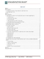
The following diagram shows the continuous sequence of bored piling works
HCMC Metro Cp-2 Project
TITLE :
Stage 1
Method Statement of
Bored Pile Construction
On Land
Stage 2
Stage 3
1.Pre-boring for temporary casing 1. Temporary casing
installation
installation by vibro hammer.
1.Pumping of bentonite slurry
for maintaining bored hole
2.Drilling of bored hole from
EGL to Design Toe Level
Stage 4
Stage 5
1.Desanding the complete bored hole
2.Bentonite in bored hole will be pumped back to
bentonite plant for treatment.
1.Lowering of reinforcement to the bored hole.
2. Hanging the rebar cage at the designed
level.
HCMC Metro Cp-2 Project
TITLE :
Method Statement of
Bored Pile Construction
On Land
Stage 7
Stage 6
1.Concreting of bored pile.
2.Pumping of displaced bentonite back to bentonite
plant.
3.Overcasted concrete 500mm above design COL.
1. Extracting temporary casing after the
completion of concreting 15 to 20
minutes.
2. Backfilling the bored hole with suitable
backfilling material 1 to 2 hours after the
completion of concreting
Fig.1 Sequence of Bored Piling Works
1.2
WORK PROCEDURE
The detail work procedure is described as follows.
(1) Preparation Works
Prior to the commencement of the Cast-in-place concrete piling works, the site will be
cleared and leveled to stand the weight of Bored Piling Machine without any obstacles at
the surface of the ground and also prepared to form working platform with sufficient
working space. And if it is not sufficient enough to stand the weight of Bored Piling
Machine, steel plate will be placed to serve as equipment working platform.
Temporary drainage system shall be provided around the platform so that the platform and
the surrounding area are kept dry and accessible all the time.
The temporary access road shall be made in case that existing road is not available for
supplying material and mobilizing to equipment.
Bentonite mixing tank will be installed for fluent execution of the work maintaining including
connection of pipe or hose to supply bentonite for the bored pile location. It will be checked
from time to time for any possible spillage of bentonite slurry as per environmental
requirement.
The density and consistency of the concrete for the bored piles shall conform to the tremie
HCMC Metro Cp-2 Project
TITLE :
Method Statement of
Bored Pile Construction
On Land
casting method and the maintenance of sufficient workability (slump) of all the concrete
during the casting and handling period, including calculated allowance delay time, shall be
secured by a design mix (including the necessary retarders and plasticizers) which is
tested by trial mixes prior to the pile construction.
The number of tank used for bentonite mixing plant shall be calculated to make sure that
the volume of mixed bentonite slurry is enough for carrying out drilling work continuously.
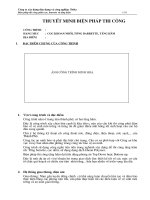
Typical layout of equipment and facilities set up for bentonite solution is shown below.
Precipitation Tank 3
Precipitation Tank 2
Precipitation Tank 1
Circulation Tank
Withdrawal Tank
Mixing Tank
Waste Tank
Mud
Screen
Circulation
Pump
Cyclone
Supply Pump
Supply Pump
Sand Pump
Another Hole
Drilling Hole
Base Machine
Drilling Hole
* Note:
Flow of stabilization liquid
Concreting
* This layout could be changed according to site condition
Fig.2 Layout of equipment and facilities set up
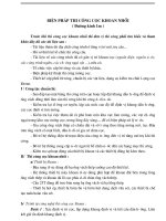
(2) Setting center point of the bored piles
Positioning drilling hole is based on the approved drawings, positioning benchmarks and
piling arrangement layout for specifying positions of pile center in compliance with the
HCMC Metro Cp-2 Project
TITLE :
Method Statement of
Bored Pile Construction
On Land
approved design. Specifying the position of the pile center is performed by electronic total
station. The position shall be approved by the Employer’s Representative.
In addition, subsidiary benchmarks shall be set up by steel piles for direction of pile center
and the pile center shall be checked again upon sinking temporary well casing. These
positions shall be protected and maintained until sinking and completing inspection of the
well casing.
Checking of the bored hole location shall also be carried out for all the piles after the
commencement of boring, but not later than when boring has reached the top of the first
stiff layer.
Pile center
Subsidiary benchmark
Datum point
Fig.3 Setting out center of Bored pile
(3) Assembling Guide frame
Assembling guide frame will be prepared before Setting of the temporary casing.
(4) Setting of the temporary casing
Bored pile construction will be commenced from setting out pile location and pre-drilling
and installing temporary casing. The length of the casing will be considered and justified
based on the soil condition and underground water level for maintaining the stability of the
pile excavation holes against collapse, the casing length is from 6m to 9m. The top of
temporary casing will be extended about 0.5 meter above the ground level.
In installation of temporary casing, the verticality and stability will be checked and nonmovement during drilling shall be kept. Inner diameter of casing pipe will be at least 5 ~
10cm larger than bored hole diameter. The casing will be plumbed and checked for
eccentricity against reference pegs, or it will be checked with survey equipment at the top
of the casing with the same elevation aside from the location frame installed above ground
level.
HCMC Metro Cp-2 Project
TITLE :
Method Statement of
Bored Pile Construction
On Land
Fig.4 Installation of temporary casing
(5) Drilling work
The design length of piles will be specified in approved drawings. During drilling
excavation, all holes for cast-in-place concrete pile should be excavated to the design
length. Excavated holes will be protected from collapse by the provision of bentonite slurry
and temporary steel pipe casing.
Fig.5 Casing
HCMC Metro Cp-2 Project
TITLE :
Method Statement of
Bored Pile Construction
On Land
Fig.6 Casing
a) Bentonite slurry
All properties of chosen bentonite shall be tested and the test results shall be submitted to
the Employer’s Representative to get approval before using.
During drilling process of bored hole, the soil wall will be protected from collapse by the
provision of bentonite slurry and temporary steel pipe casing. Prior to drilling works, the
stabilization liquid as the bentonite suspension will be prepared and tested to meet the
criteria which will be proposed before commencement.
Bentonite will be mixed thoroughly with clean fresh water to make a suspension which will
maintain the stability of the drilled hole for the period of casting concrete and complete
construction. Dry powder Bentonite is mixed with clean water according to required ratio by
mixing machine and stored in the tanks which will supply to bored hole. The drilling fluid
properties of bentonite slurry will be measured by taking samples before concreting. The
density of freshly mixed bentonite slurry will be measured as a check on the quality of the
suspension being formed.
b) Setting up of Bentonite Plant
The following are the various stages of works in the setting up of site facilities:
Setting up
Installation of desander unit.
Preparation and levelling of ground.
Installation of bentonite silos.
Setting up of bentonite plant facilities.
Layout of bentonite and water piping systems.
Pre-mixing of bentonite slurry on site.
HCMC Metro Cp-2 Project
TITLE :
Method Statement of
Bored Pile Construction
On Land
c) Bentonite Slurry Mix Design
Basic function of bentonite is to act as a stabilizing agent for the bored hole.
In soil with high clay content, the bentonite slurry becomes very thick during excavation
due to the suspended clay particles. The thick slurry becomes difficult to pump for
desanding. To avoid this problem, a polymer / sodium bi-carbonate is added to the slurry.
d) Testing Bentonite Slurry
Bentonite Slurry Testing:
The following tests will be conducted on bentonite slurry at the beginning and during bored
pile construction period.
1. Viscosity test - test on site
2.
Sand Content – test on site
3.
Density test - test on site
4.
pH meter test - test on site
Bentonite characteristics have to meet the requirement (refer to Sub-clause 6.3
Tolerance/Range, page 24-25).
The bentonite properties shall be measured by taking samples at the bottom of bored hole
before concreting. All checking of bentonite slurry shall be carried out complying with the
criteria proposal. The measuring device shall be calibrated to read in the minimum unit of
0.01gm/ml.
0.5-1.0 m above G.L
Bentonite
Fig.7 Bentonite Slurry
HCMC Metro Cp-2 Project
TITLE :
Method Statement of
Bored Pile Construction
On Land
e) Drilling works
Temporary casings shall be free from any significant distortion. They shall be of uniform
cross- section throughout each continuous length. During concreting, they shall be free
from internal projections and encrusted concrete which might disturb the proper formation
of piles.
From the ground level to one meter above the toe of the temporary casing will be drilling
without stabilization bentonite. The measurement of the depth of drilling bucket shall be
closely monitored when it gets near of the toe of the temporary casing.
After putting bentonite into the borehole, drilling work will be continued and the top level of
bentonite slurry will be maintained 1.5m higher than ground water level or equal with
ground level for prevention of cave-ins or bored hole collapses.
Based on the soil properties, drilling speed is adjustable in order to maintain the drilling
accuracy.
The soil materials encountered in the bored pile drilling shall be checked to confirm
whether the actual soil conditions are similar to those assumed based on the geotechnical
investigation boreholes or not.
During the drilling work, the verticality of bored hole will be checked by plumb with string
line or theodolites from two directions in 90 degree. And the depth of bored hole will be
checked for the conformation of borehole condition. When the bucket is lifted up, the
bucket is to be rotated reversibly to release from the bottom and to be lifted up slowly to
protect the hole from collapse.
Kelly-Bar shall be kept at the centre of the casing because drilled holes start to bend with
Kelly-Bar’s deviation from the centre. In case any the deviation is found, the drilling should
be operated slower than usual and to correct the Bar’s verticality.
After a borehole is formed to the designated depth, sonic caliper test (Koden Test) shall be
carried out for checking the depth, diameter and verticality of the boreholes.
Bentonite introduced into the borehole achieves the stabilizing effect by ensuring that the
pressure inside the borehole is greater than the horizontal soil pressure and groundwater
pressure, at all depths.
Piles shall not be bored so close to the piles, which have been casted not long ago with
workable or unset concrete. The piling may disturb the fresh concrete in the neighboring
piles. Boring and excavation for a pile shall only be commenced 24 hours after completion
of any pile within a radius of 6.0m, center to center, and only after the concrete strength of
the neighboring pile reaches 15N/mm2.
The excavated material and disposal bentonite will be kept in tanks or containers then
transported to approved disposal areas by special trucks. The proposed disposal areas will
be submitted to the Employer’s Representative for approval later and separately.
(6) 1st Cleaning bottom of the holes & Changinh Bentonite
For the supply of fresh bentonite slurry, tank for fresh bentonite slurry will be installed at
the position which is separated apart from the bentonite pit.
HCMC Metro Cp-2 Project
TITLE :
Method Statement of
Bored Pile Construction
On Land
The sequence of cleaning work for the bottom of hole is as below:
- Using cleaning bucket to remove lumps of clay, coarse sand and gravels at the
bottom of the borehole. Then,
- Using reverse circulation method or air lifting method for replacing sedimentation of
slime with good slurry.
After cleaning work, the depth of hole will be measured by measuring tape connected to a
plump bob. Measuring of hole will be carried out at the center and four corners of the hole.
Fig.8 Cleaning by cleaning bucket
(7) Fabrication and Installation of the rebar cage
Fabrication of rebar cage:
Steel bar shall be tested when delivery to site and only approved steel bar will be used.
Rebar cages, sonic tube and core tube will be fabricated and assembled according to the
approved construction working drawing.
After the completion of fabrication for one segment of rebar cage, this segment shall be
carefully kept in the dry and stable condition at stockyard which is elevated about 20 cm
higher than ground surface level. Condition of re-bar cage will be checked and cleaned
constantly. If some soil or rust are pound remained on the re-bar cage, all of them shall be
removed before the installation of re-bar cage.
Additional reinforcing ring will be used for hanging of rebar cage segment and for the cage
stabilized against distortion.
HCMC Metro Cp-2 Project
TITLE :
Method Statement of
Bored Pile Construction
On Land
Fig.9 Reinforcement fabrication
Installation of rebar cage and sonic tubes and core tube:
After the 1st cleaning of borehole is completed, the rebar cage will be installed carefully in
order to avoid the wall of the borehole from collapsing. The lowest rebar cage segment will
be put into the casing and temporarily fixed at the section to be spliced with the next rebar
cage segment. When the rebar cage reaches the designed level, it will be suspended from
top of the casing. The top level of the rebar cage will be confirmed in comparison to that of
the casing.
The ultra-sonic tubes and core tube will be fixed to rebar by additional bar and ties to the
rebar cage. Top level of the sonic tubes and core tube will be positioned approximately
15cm above the ground level and checked for the rigidity and watertight of tubes during
installation. The sonic tubs and core tube will be poured with water and covered on the top
of tubes prior to casting concrete.
HCMC Metro Cp-2 Project
TITLE :
Method Statement of
Bored Pile Construction
On Land
Fig.10 Installation of the rebar cage
(8) Setting of Tremie Pipe and Re-cleaning (2nd Time Clearing) of Bored hole
a) Setting of Tremie Pipe
Tremie pipes of dia. 8-10 inches shall be used. The tremie pipes with standard length,
such as 0.5M, 1M, 2M, 3M and 6 M, shall be used.
Since the tremie pipes are segmented and connected by bolts as a flange type and a
rubber gasket will be used therein to watertight, these are lowered piece by piece until it
reaches to the bottom of the borehole. And the tip of tremie pipe will be at least 300mm
away from the bottom of bored hole in order to have enough clearance in discharging of
concrete. The top of tremie pipe is fitted with a head hopper.
HCMC Metro Cp-2 Project
TITLE :
Method Statement of
Bored Pile Construction
On Land
The length of each tremie pipe and the sequence of installation shall be recorded
completely.
Fig.11 Tremie Pipe
b) Re-cleaning of the Borehole (2nd Time Cleaning)
Prior to placing concrete, the depth of bored hole will be measured carefully and the
bentonite slurry will be tested once again, and the second time cleaning of pile base will be
carried out if required by the Employer’s Representative with 1 of 2 methods:
1. Airlifting method: Air-lift system will be used as second measure to take all slime out of
the bottom of bored hole, before casting concrete. The pressure of compressed air has
to be properly checked. Since stabilizing fluid is supplied to the piling hole, the
compressed air will create an upward jet flow which carries the bottom sludge out of the
hole. The circulating time of airlift varies depending on the amount of bottom sludge.
2. Reverse circulation method: using the capable submerged pump connected to tremie
pipe for removing the slime sedimentation at the bottom of bored hole and replacing by
fresh slurry.
A measurement tape is to be used for the re-confirmation of drilling depth and effect of
cleaning work. The concrete placing will be started as soon as possible (approx. in 30
minutes) after second cleaning of bottom of bored hole. And before casting concrete, it will
be confirmed by measurement tape that the sedimentation has been removed completely.
(9) Casting concrete
Fresh concrete shall be applied to cast-insitu pile and concrete will be mixed at batching
plants then supplied to site by mixer trucks. The proportion of ready mixed concrete shall
be tested and approved by the Employer’s Representative before using. Only specified
ready mixed concrete will be used. The summary is as below:
HCMC Metro Cp-2 Project
TITLE :
Strength
class/
Description
Grade 30
Max. size
of
aggregate
(mm)
20
Method Statement of
Bored Pile Construction
On Land
Slump
(cm)
18 to 25
Compressive
strength at 28
days (Cylinder)
30 N/mm2
Cement Contents
356Kg/m3
Prior to commencement of the concrete casting work, the following checking will be
executed for preventing the tremie pipe from blocking.
* Workability of concrete.
* Selection of the suitable tremie pipe (diameter, length per pipe and joint)
* Check of pipe joints leakage (visual Inspection)
Once again taking of Bentonite samples at the bottom of the bored hole by special
equipment and testing shall be performed before pouring concrete.
Concrete will be placed and poured directly to the bored hole in one continuous operation
from tip to cut-off elevation by tremie pipes and this operation will be carried out in such a
manner that segregation of concrete is avoided. The tip of the tremie will generally be
approximately 2.0m lower than the casting concrete surface. A sliding plug or similar
barrier will be placed within the tremie pipe to prevent direct contact between the first
charge of concrete and the water or bentonite.
Fig.12 Casting concrete
The schedule for casting concrete will be confirmed in order to ensure concrete pouring
continuously without interruption. Hence the top of concrete is contaminated by mixing with
stabilization liquid; extra volume of concrete is to be used for confirmation of the clean
HCMC Metro Cp-2 Project
TITLE :
Method Statement of
Bored Pile Construction
On Land
concrete. The height of extra or surplus concrete is proposed to be more than 0.5m from
cut-off level; however this may be adjusted in consideration of the site condition.
Tremie pipes are chocked with tremie support and clean immediately after disconnection to
avoid clogging of concrete inside of the pipes.
It is required to check the elevation of casting concrete in the bored hole by special tape
and plumb to control elevation of the tremie pipe bottom suitably and to detect immediately
any collapsing or narrowing of bored holes. Collapse or necking of borehole may be
detected by comparison of the calculated volume of the bored hole with the actual volume
of concrete poured into the borehole.
(10)
Removal of Temporary Casing
Temporary casing shall be withdrawn 15 minutes to 20 minutes after concreting by using
the draw and spin system of drilling machine or using vibro-system in vertical direction to
make sure the stability of pile head and degree of accuracy of pile center.
After removal of temporary casing, from 1 hour to 2 hours, the bored hole will be filled by
soil and/or sand.
2
RESOURCES TO BE USED
3.1
EQUIPMENT TO BE USED
For the successful implementation of bored piling works, the following equipment will be
mobilized. The list of equipment for a typical working party is shown below. Bored pile
works will be carried out with the following equipment.
The List of Equipment for One Typical Working Party
No.
Item
1
Drilling machine
Kelley
or
RCD
equivalent machine
2
Service Crane
40~50t class crawler type
4
Diesel Generator
For welding
6
Airlift pipe
For cleaning borehole
7
Water Pump
For the circulation of bentonite slurry
8
9
10
Description
Pouring concrete
platform
Bar
Cutter
machine
Bar
Bending
Machine
11
Air Compressor
12
Tremie Pipe
Remarks
or
For excavation of bored hole
For handling of steel cages and
concreting works
For casting bored pile
For fabricating rebar cages
For fabricating rebar cages
For airlifting (Cleaning)
80m
For cleaning borehole
HCMC Metro Cp-2 Project
TITLE :
Method Statement of
Bored Pile Construction
On Land
13
Drilling Bucket
D = 1000~1500mm
Boring tools
14
Cleaning Bucket
D = 1000~1500mm
Boring tools
15
Casing Pipe
D = 1050~1550mm
For excavating of borehole
16
Bentonite Tank
17
18
19
20
Concrete Mixer
Truck
Bentonite
Desander
Survey
Equipment
Measuring Tape
with Plumb Bob
21
Empty tanks
22
Excavator
For the circulation of bentonite slurry
6 m3
For bored pile casting
Total Station / Auto Level
Setting center point and elevation
pile
For measuring depth of borehole
For containing excavated material
and disposal bentonite
For preparation work and support
work
* The equipment (type and quantity) might be changed depending on the site situation.
HCMC Metro Cp-2 Project
TITLE :
3.2
Method Statement of
Bored Pile Construction
On Land
ORGANIZATION
Organization chart for Cast-in-place Concrete Piling Work are shown below.
Construction Manager
(Mr. Kim Dong Wan)
Quality Manager
(Mr. Myung Jai Sin)
Safety Manager
(Mr. Hwang Ki Ha)
Environmental Manager
(Mr. Tran Thanh Lap)
Survey Team
Site Manager
(Mr. Lee Jung Sun)
Site Engineer
(Mr. Mai Song Thao)
Subcontractor’s Project Manager
Subcontractor’s Engineer
Operator
2.1
Skill Labor
Common Worker
Electrician
Welder
RESPONSIBILITY OF STAFF
The following staff / personnel will be deployed on site to comply with the approved
construction drawings and as per the specifications and the construction programmed.
Project Manager – Overall Supervision
Construction Manager – Coordinate with the Employer’s representative for the Execution,
Quality and safety
Site Engineers, Surveyor & QA/QC Staff – Execution, Quality and Safety, Follow Up
Quality Control Procedures and submission of quality Forms and records on daily
activities
QA/QC Manager:
In charge of laboratory’s works; compose QC Plan; inspect materials and construction
works’ quality; ensure the quality control implementation in according to ITP
Responsible for inspection and establishes all relevant procedures and initiates
coordination with relevant inspection parties.
HCMC Metro Cp-2 Project
TITLE :
Method Statement of
Bored Pile Construction
On Land
HSE Manager:
Carry out the necessary measures and/or procedures to ensure the implementation of
HSET Plan (Health, Safety, Environment, and Traffic).
3
CONTINGENCY AND SOLUTION
The possible contingency and solution during piling work will be described below.
3.1
CONTINGENCY OF DRILLING WORK
(1) Sand piping
The steel standing casing will be installed into the ground to protect the drilled hole from
collapsing due to the weight of working machines. However, piping may occur due to
insufficient penetration depth or penetrating into a sand layer. This occurrence may result
in water level dropping suddenly, drilling surface collapsing, and the standing casing
lowering or tilting. To solve this situation, either increases the casing length or withdraws
the casing and backfill immediately and re-excavate after the backfill consolidated.
(2) Collapse because of excessive loads
Potential collapse may occur due to the excessive loads. Before drilling, equipment
which is not necessary should be removed for drilling. Increasing the viscosity of slurry or
the length of standing casing may reduce the risk of collapse. When large collapse
happens, all the equipment will be removed and the hole will be backfilled immediately.
For several days, the pile could be drilling again after covering the ground of the borehole
with steel plates and increasing the casing length (if necessary).
(3) Insufficient water head
Insufficient water head in the drilled hole may result in the collapsing of the drilling
surface. Spillage leakage into ground may occur while the high permeable layer is
encountered. Therefore, the water level within the drilled hole shall be inspected regularly
and frequently. Additional slurry or other solutions may be needed to keep slurry from
flowing into the high permeable layer.
(4) Vibration effect
The distribution of heavy equipment should be located evenly around the piling area to
avoid excessive loads or unbalanced loads. Also, vibration effect may occur due to earth
tremor or ground shaking caused by heavy equipment. According to previous working
experience, heavy equipment should be placed at a good distance away from the
borehole location to ensure the safety of equipment and personnel during piling work.
(5) Hindrances in pile position
In some occasions, huge rock or rotten wood may be encountered during drilling. Care
and patience should be taken to break or penetrate such objects. Increasing working
torque or rate may cause ground shaking and damage the drilling surface.
(6) Drill bit and pipe dropping
HCMC Metro Cp-2 Project
TITLE :
Method Statement of
Bored Pile Construction
On Land
During the drilling process, it is possible that the drilling bit and pipe snaps and drops
suddenly down to the drilled hole. When this accident happens, workers stop drilling and
try to hook and drag the dropped bit and pipe immediately with the wire with hook of
crane.
3.2
CONTINGENCY OF SUCCESSIVE WORK
(1) Rebar cage dropping into the drilled hole
When the rebar cage drops into the drilled hole, the installation should be stopped
immediately. The dropped cage should be recovered by using the wire with hook, which
is enough to recover the falling cage. After recovering, the condition of the cage should
be check to make sure that the cage quality is still accepted for structural use. Another
section will be needed if the cage is not accepted. In order to prevent the cage from
falling or dropping, the connecting points among rebars and hanging bars should be
carefully inspected. After removing the rebar cages the depth of borehole shall be
checked again to make sure the drilled depth before re-installing rebar cages.
(2) Tremie pipe dropping into the hole before concrete placing
Care should be taken while inserting tremie pipes into the hole. When the tremie pipe is
dropped into the hole before concrete placing, the work should be stopped. A large hook
will be used for recovering the dropping pipe from the hole and resume the work.
(3) Tremie pipe out of the placed concrete
If the bottom of tremie pipe be out of the placed concrete due to the pipe blocked, it is a
practicable choice to re-penetrate the cleaned tremie pipes into the placed concrete
before the initial set of concrete, to vacuum water and slurry in the tremie pipe and to
continue placing concrete.
The procedure of work shall be checked carefully at the points of:
The taken time should less than the setting time of used concrete and as soon
as possible.
The volume of bentonite slurry inside the tremie pipe.
The toe of tremie pipe inside poured concrete at least 2m.
The procedure of the treatment shall be recorded completely and accurately. The
integrity test of the pile shall be executed after 7 days to confirm the structural capability.
(4) Collapse during concrete placing
When placing concrete, there are chances that the wall of hole has collapsed if the water
level suddenly increases or decreases. The placing work should be stopped immediately,
and check the elevation of the concrete surface carefully. Base on actual elevation and
collapsed quantity, decide to stop pouring or continue placing concrete after discussion
with the Employer’s Representative on site.
4
4.1
GROUND MOVEMENT AND SOLUTION
GROUND MOVEMENT
-
The ground movement could happen due to bored piling works especially:
-
If borehole wall is collapsed and surrounding soils are flowing into the boreholes
HCMC Metro Cp-2 Project
TITLE :
Method Statement of
Bored Pile Construction
On Land
together with groundwater.
4.2
-
If groundwater flows into the boreholes together with soils at the base of the
boreholes (boiling of sandy soil ground at the base of the borehole)
-
If groundwater level of surrounding ground was lowered
SOLUTION
In order to prevent ground movement during piling work, these solutions will be applied:
-
In case of problem arise, bentonite shall be densified and extend the temporary
casing.
-
Bentonite shall be kept more than 1.5m above from existing groundwater level,
described in fig. 13.
Fig. 13 Bentonite and ground water level
5
5.1
QUALITY CONTROL
QUALITY CONTROL
All material will comply with the requirements in the Outline Construction Specification
and the required inspection and test on site will be carried out in compliance with the ITP
and quality control plan. ITP will be submitted to the Employer’s Representative
separately.
5.2
SEQUENCE OF INSPECTION AND TEST
HCMC Metro Cp-2 Project
TITLE :
Method Statement of
Bored Pile Construction
On Land
a) Steel reinforcement
Each sample of steel reinforcement shall be tested to determine the yield stress,
elongation, tensile strength, bending properties and unit mass.
Each sample of reinforcement couplers for tension joist shall be tested to determine the
tensile strength and the permanent elongation, if any.
The method of testing shall be in accordance with JIS G 3112 or JIS G 3117 or
equivalent ASTM standards.
These tests shall be carried out by the consented testing authority.
Rate of sampling of reinforcement are performed by the this table
The number of Steel reinforcement specimens in each sample shall be as follows
Reinforcement U-Clip for tension joint: 3
Each specimen of steel reinforcement shall be 1m long. Each specimen of reinforcement
U-Clips shall consist of one reinforcement U-Clip jointed two lengths of bar each 500mm
long. The bars shall be of the same type, size and grade as the bars to which the
reinforcement U-Clips will be fixed in the Permanent Works. Each specimen of steel
reinforcement shall be taken from different bars. The ends of the specimen shall be cut
square before delivery to the laboratory.
b) Ready Mixed Concrete
HCMC Metro Cp-2 Project
TITLE :
Method Statement of
Bored Pile Construction
On Land
The ready-mixed concrete shall be obtained only from a supplier agreed by the
Employer’s Representative .
Contractor shall submit the Mix Design Ready Mixed Concrete to the Employer’s
Representative for his approval.
Ready-mixed concrete shall comply with the requirements of JIS A 5308 or equivalent
Vietnamese Standards and those specified herein and shall comply with all requirements
of the Contract.
The concrete shall be carried in purpose-made agitators, or truck mixers, operate
continuously. The concrete, shall be compacted and in its final position within 2 hours of
the introduction of cement to the aggregates, unless a longer time is agreed by the
Employer’s Representative. The time of such introduction shall be recorded on the
Delivery Note, together with the weight of the constituents of each mix.
The Contractor shall make the supplier aware of all Specifications requirements and of
his program, construction methods, rates of concreting, access, and all other criteria
which may affect the supplier's performance in any way.
Sampling and Testing shall be in accordance with the following specification and
Inspection and Test Plan
No
1
Test Item
Compressive strength of Cylindrical Concrete
Specimens
Standards
JIS A 1108 or
AASHTO Test Method T22
2
3
Making and Curing Concrete Compressive and
Flexural Strength Test Specimens in the Field
Obtaining and Testing Drilled Cores
4
Sieve Analysis of Fine and Coarse Aggregate
5
Specify Gravity
Aggregate
JIS A 1132 or
AASHTO Test Method T23
JIS A 1107 or
AASHTO Test Method T24
JIS A 1102 or
AASHTO Test Method T27
JIS A 1109 or AASHTO Test
Method T84
6
Related testing for Fine Aggregate
7
Specify Gravity and Absorption of Coarse
Aggregate
and Absorption
of
Fine
Refer to sub-clause 5.1.2
(3)
JIS A 1110 or
AASHTO Test Method T85
The frequence of testing and sampling of fresh concrete at construction site are
performed by the this table
No
1
2
3
Item
Temperature of concrete
Slump of concrete
Cylinder sample
Frequence
Remark
Every truck
Every truck
1 set / every 30m3, Base
on
Outline
not less than 1 set / Construction Specifications
1pile
c) Testing of Bentonite Slurry
The following tests will be undertaken on the bentonite slurry to monitor the performance