Tài kiệu kỹ thuật về máy đóng nang và dập viên
Bạn đang xem bản rút gọn của tài liệu. Xem và tải ngay bản đầy đủ của tài liệu tại đây (3.43 MB, 273 trang )
Tablet and Capsule Machine
Instrumentation
Tablet and Capsule Machine
Instrumentation
Edited by
Peter Ridgway Watt
MSc, PhD, CChem, FRSC, CPhys, FInstP
Formerly Instrument Services Co-ordinator
Beecham Pharmaceuticals Research Division
Brockham Park, UK
and
N Anthony Armstrong
BPharm, PhD, FRPharmS, FCPP
Formerly Senior Lecturer in Pharmaceutics
Welsh School of Pharmacy
Cardiff University, Cardiff, UK
London
•
Chicago
Published by the Pharmaceutical Press
An imprint of RPS Publishing
1 Lambeth High Street, London SE1 7JN, UK
100 South Atkinson Road, Suite 200, Grayslake, IL 60030–7820, USA
© Peter Ridgway Watt and N Anthony Armstrong 2008
is a trade mark of RPS Publishing
RPS Publishing is the publishing organisation of the Royal
Pharmaceutical Society of Great Britain
First published 2008
Typeset by J&L Composition, Filey, North Yorkshire
Printed in Great Britain by TJ International, Padstow, Cornwall
ISBN 978 0 85369 657 5
All rights reserved. No part of this publication may be reproduced, stored in a retrieval system, or transmitted in any form or
by any means, without the prior written permission of the copyright holder.
The publisher makes no representation, express or implied,
with regard to the accuracy of the information contained in this
book and cannot accept any legal responsibility or liability for
any errors or omissions that may be made.
The right of Peter Ridgway Watt and N Anthony Armstrong
to be identified as the authors of this work has been asserted
by them in accordance with the Copyright, Designs and Patents
Act, 1988.
A catalogue record for this book is available from the British
Library
Dedication
I first met Peter Ridgway Watt about 30 years
ago when we were both speakers at a very early
conference on instrumented tablet presses. We
quickly found that we had many interests
in common. In 1988, Peter brought out his
textbook on instrumentation, Tablet Machine
Instrumentation in Pharmaceutics, and we collaborated several times in organising short courses
on the topic. It was at one of the most recent of
these that Peter and I decided that a revision of
his textbook was called for, to be written partly
by us, but inviting experts in certain areas to
contribute chapters on selected topics. Peter
threw himself into the task, but his health began
to fail, and he died on 12 February 2007, only
five days after the text of the one remaining
chapter had been received.
This book is dedicated to Peter Ridgway Watt,
an inspiring colleague and a good friend.
N Anthony Armstrong
Harpenden, UK
February 2007
v
Contents
Preface
xi
Contributors
1
xiii
Introduction
1
N Anthony Armstrong
Introduction 1
A brief overview of instrumented systems 2
Units of measurement 4
The instrumentation of tablet presses and capsule-filling equipment
References 8
Further reading 9
2
The measurement of force
6
11
Peter Ridgway Watt
Introduction 11
Strain measurement 12
Strain gauges 13
Siting strain gauges 22
The Wheatstone bridge circuit
Load cells 38
Miscellaneous methods 46
References 49
3
32
The installation of strain gauges
51
Anton Chittey
Introduction 51
Health and safety considerations
Surface preparation 51
Bonding with adhesive 53
Leadwire attachment 57
Protection of the installation 58
Inspection and testing 58
Specialist applications 59
51
vii
viii
Contents
Tools and installation accessories
Professional assistance 63
References 64
Further reading 64
4
61
The measurement of displacement
65
Peter Ridgway Watt
Introduction 65
Displacement transducers with analogue output 65
Displacement transducers with a digital output 76
Dynamic measuring devices 79
Miscellaneous methods of displacement measurement
References 84
5
82
Power supplies and data acquisition
87
Peter Ridgway Watt
Introduction 87
Gauge excitation level 87
The power supply unit 88
Mains noise 89
Battery power 91
Power supply to and data acquisition from tablet presses
Signal display 95
References 97
6
Instrumented tablet presses
91
99
N Anthony Armstrong and Peter Ridgway Watt
Introduction 99
The eccentric press 99
Rotary tablet presses 111
The measurement of displacement in tablet presses 119
Measurement of ejection forces 127
Measurement of punch pull-up and pull-down forces 129
Measurement of punch face adhesive forces 131
Instrumentation packages 132
References 136
7
Calibration of transducer systems
Peter Ridgway Watt
Introduction 139
Force 140
139
Contents
Displacement 142
Calibration problems
8
ix
145
Data handling
147
Alister P Ridgway Watt
Introduction 147
Sampling system theory 147
Electronics sub-systems 153
Embedded systems 157
Computer interfacing 157
Software 162
Data backup 163
Further reading 165
9
Applications of tablet press instrumentation
167
N Anthony Armstrong
Introduction 167
Punch displacement–time profiles 168
Force–time profiles 176
Force–porosity relationships 182
The force–displacement curve 187
Punch velocity 190
Die wall stress 196
Applications of press instrumentation to lubrication studies
References 202
Further reading 205
10
201
The instrumentation of capsule-filling machinery
207
N Anthony Armstrong
Introduction 207
Capsule-filling equipment 208
Instrumentation of dosating disk capsule-filling machines 209
Instrumentation of dosating nozzle capsule-filling machines 214
References 220
Further reading 222
11
Automatic control of tablet presses in a production environment
Harry S Thacker
Introduction 223
The force–weight relationship
Monitoring systems 225
224
223
x
Contents
Control systems 225
Reject systems 226
Weighing systems 227
Computer-controlled systems
References 239
Further reading 240
228
Appendix: Suppliers of materials and services
Index 249
241
Preface
W H E N W I L L I A M B R O C K E D O N patented the
notion of ‘shaping pills, lozenges and black lead
by pressure in dies’, he could hardly have imagined the extent to which this apparently simple
idea would grow. It was largely this invention
that extended the industrial revolution to the
preparation of medicines, giving rise to the pharmaceutical industry as it now exists. Individual
pharmacies would no longer need to make up
small quantities of medicines themselves, largescale production in a relatively small number of
manufacturing sites was now feasible, and
mechanical engineering methods could be
applied to the process.
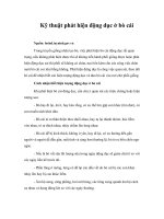
In Brockedon’s original invention (Figure P1),
the upper punch was removed so that powder
could be loaded into the die. The punch was
replaced and was then struck with a mallet to
compress the charge between the faces of the
two punches. It would have been possible to
make a few tablets in a minute.
At the present time, there are rotary tablet
presses with many sets of punches and dies that
are capable of making compressed tablets at a
rate of up to one million in an hour. Yet for more
than 100 years, the satisfactory operation of the
process was dependent on the skill and experience of the men who ran the machines. They
might evaluate a tablet by breaking it in half and
listening to the snap, but they did not have
the facility to measure what was happening in
accurate detail.
Since the 1960s, the situation has changed
dramatically. We have reached a point where we
Upper punch
Die body
Lower punch
Figure P1
Schematic view of Brockedon’s original punch and die assembly.
xi
xii
Preface
are in a position to measure many variables
before, during and after the compaction event,
and to use the constant stream of information to
control the press automatically. In this book, we
have described a selection of measuring devices
that have been developed in the general field of
engineering instrumentation, and we have
shown how some of them have been applied in
our particular area of interest. Readers might be
concerned that many of the references quoted
are of some considerable age, but in fact there
has been little published work on new measuring
systems for several decades. The most significant
advances have been in the field of electronics,
and the application of computer techniques to
data acquisition and processing, but measuring
devices such as strain gauges and displacement
transducers have not changed greatly since the
1980s.
As for the equipment described in these pages,
we have assumed little prior knowledge on the
part of the reader and have attempted to define
any new terms as they appear. Many tablet press
manufacturers offer machines that are already
fitted with measuring devices and data processing systems. Nevertheless, it is still necessary to
understand the essential principles of press
instrumentation, the importance of transducer
selection, siting, and calibration, and to have an
appreciation of what a particular instrumentation technique can and – equally important –
cannot do. It is our hope that these pages will
help to promote such understanding.
Of course, the idea that research progresses
smoothly from one stage to the next is a myth,
usually supported by papers and publications
that conveniently omit all mention of the dead
ends and disasters that happen in real life.
We have, therefore, included a few anecdotes
from our own experience, which confirm the
hypothesis that if something can go wrong, it
will!
N Anthony Armstrong and
Peter Ridgway Watt
February 2007
Contributors
N Anthony Armstrong
Harpenden, UK
Formerly Senior Lecturer in Pharmaceutics,
Welsh School of Pharmacy, Cardiff University,
Cardiff, UK
Peter Ridgway Watt
Formerly Instrument Services Co-ordinator,
Beecham Pharmaceuticals Research Division,
Brockham Park, UK
Anton Chittey
Technical Support Engineer, Vishay
Measurements Group UK Ltd, Basingstoke, UK
Alister P Ridgway Watt
Technical Director, QBI Ltd, Walton on Thames,
UK
Harry S Thacker
Ormskirk, UK; formerly of Manesty Machines,
Knowsley, UK
xiii
1
Introduction
N Anthony Armstrong
Introduction
The year 1843 saw the publication of British
Patent Number 9977. It was issued to William
Brockedon, an English inventor, and its object
was that of ‘shaping pills, lozenges and black
lead by pressure in dies’. This marked the introduction of the dosage form now known as the
tablet. Brockedon did not set out to invent a
dosage form. His original aim was to reconstitute
the powdered graphite left as a waste product
when natural Cumberland graphite was sawn
into narrow strips for pencil ‘leads’. However,
he later realised that his invention could be
applied to the production of single-dose units of
medicinally active compounds.
The introduction of the tablet marked the
impact of the Industrial Revolution in the
production of medicines and opened up a
whole range of new possibilities for the pharmaceutical industry. Compared with earlier
dosage forms such as the pill, it offered a stable,
convenient form that was capable of being
mass produced by machines. Furthermore, with
appropriate formulation, a range of different
types of tablet could be produced, including
those to be swallowed intact, sucked, held
within the buccal pouch or under the tongue,
dissolved or dispersed in water before ingestion,
or so formulated that the active ingredient is
released in a controlled manner. So popular has
the tablet become that it has been estimated
that of the 600 million National Health Service
prescriptions written per annum in the UK, over
65% are for tablets. There are 336 monographs
for tablets in the 2005 edition of the British
Pharmacopoeia.
The original Brockedon press consisted of a die
and two punches, force being applied by a blow
from a hammer. Mechanised versions of this
device soon followed, either eccentric presses
with one die and one set of punches or rotary
presses with many sets of tooling. A modern
rotary press can turn out approximately one
million tablets every hour, rejecting any that are
unsatisfactory. Such presses are often designed to
operate without continuous human supervision,
and to achieve this aim, highly sophisticated
control systems are required. However, all tablet
presses involve compression of a particulate solid
contained in a die between two punches, which
is essentially Brockedon’s invention.
The capsule originated at about the same time
as the tablet. The first recorded patent was
granted in 1834 to two Frenchmen, Dublanc and
Mothes. This was a single piece unit that today is
usually referred to as a soft-shell capsule, the
contents of which are almost invariably liquid or
semisolid. The hard-shell capsule was invented a
few years later in 1846 by another Frenchman,
Lehuby. Such capsules consist of two parts, the
body and the shell, and are usually made from
gelatin. The fill is almost always a particulate
solid, and the filling process usually involves the
application of a compressive force. Hard-shell
capsules also proved to be a popular dosage
form, and there are 64 monographs for hardshell capsules in the 2005 edition of the British
Pharmacopoeia.
Research into the formulation and manufacture of tablets, and to a lesser extent that of
hard-shell capsule fills, soon followed but suffered from a major handicap. Many tablet properties – thickness, crushing strength, resistance to
1
2
Tablet and capsule machine instrumentation
abrasion, disintegration time, release of active
ingredient – are dependent on the pressure that
has been applied to the tablet during manufacture. If the means of accurately measuring the
applied pressure are lacking, it follows that
meaningful studies are impossible.
Measuring the force applied to a tablet in a
press was not easy, given the constraints of early
twentieth century technology. Even using the
relatively simple presses of that era, the compression event lasted only a fraction of a second,
and hence the measurement system had to react
to the change in pressure sufficiently rapidly.
Mechanical devices, owing to their inherent
inertia, were not appropriate for this purpose.
Such devices are suitable for measuring pressure
during a longer-lasting event (e.g. compression
in a hydraulic press), but this is unrealistically
slow in terms of tablet manufacture.
It is instructive to consider how the pressure in
a tablet press arises. As the punch faces approach
each other, the volume containing the particulate solid decreases. When the solid is in contact
with the faces of both punches, then pressure
exerted by one punch will be transmitted
through the solid mass and will be detected at
the other punch. The magnitude of the pressure
is thus a function of the distance separating the
punch faces.
Many presses have some form of mechanical
indication of pressure. For example, the Manesty
F3 press has an eccentric cam graduated with a
linear scale. The reading on this scale is related to
the depth of penetration of the upper punch
into the die. It takes no account of lower punch
position and, therefore, is not a measure of the
distance separating the punch faces. The relationship between punch separation and pressure is
not linear, and it must be borne in mind that
the relationship between pressure and punch
face separation differs for different solids.
Consequently, though the graduated scale gives
a useful reference point, it is not a device for
actually measuring pressure.
The major step that enabled compression pressure in a tablet press to be directly measured was
the independent discovery by Simmons and by
Ruge in 1938 that wires of small diameter could
be bonded to a structure to measure surface
strain. Since strain is proportional to force, this
marked the invention of the strain gauge as a
device for measuring force. The strain gauge was
developed considerably during World War Two,
primarily in the aircraft industry. Its application
to tablet presses soon followed. The construction
and mode of operation of the strain gauge is
described in Chapter 2. However, its essential
characteristic, namely representing force in
terms of an electrical signal, means that force in
the die of a tablet press can be directly measured
in situ with the press operating at its normal rate
of production.
The first report of the use of strain gauges in a
study of tablet preparation was made by Brake at
Purdue University in 1951. This report was in
the form of a Master’s thesis that unfortunately
was never published as a conventional scientific
paper. A year later, the first in a series of papers
entitled ‘The physics of tablet compression’ was
published by T. Higuchi and others at the
University of Wisconsin. In one of the earlier
papers in the series, the term ‘instrumented
tablet machine’ was used for the first time.
The importance of this series, publication of
which continued until 1968, cannot be overemphasised and it can be said to have initiated
the systematic study of the tabletting process
and of tablet properties.
Further important steps in the development of
instrumented tablet presses and capsule-filling
equipment are given in Table 1.1. The instrumented tablet press, with its output often linked
to a computer, is now a widely used research tool.
In the pharmaceutical production environment,
many presses are routinely fitted with some form
of instrumentation during construction.
A brief overview of instrumented
systems
The basic components of an instrumented
system are shown in Figure 1.1.
All instrumentation systems have several
essential attributes:
• a transducer of appropriate sensitivity
• a suitable site for fixing the transducer to the
equipment
Introduction
Table 1.1 Historical milestones in the instrumentation
of tablet presses and capsule-filling machinery
1951
1952–1968
1954
1967
1971
1972
1972–1977
1980
1982
Utilisation of strain gauges in tablet
preparation by Brake, Purdue
University, USA
‘The physics of tablet compression’ a
series of papers by T Higuchi et al.,
University of Wisconsin, USA
First use of the term ‘instrumented tablet
machine’ by Higuchi et al. (1954)
The instrumentation of a rotary tablet
press reported by Knoechel et al.
(1967), Upjohn, Kalamazoo, USA
The first reported linking of an
instrumented tablet press to a computer
by de Blaey and Polderman (1971),
University of Leiden, Netherlands
The first report of a tablet press
simulator (Rees et al., 1972, Sandoz,
Switzerland)
Instrumentation of capsule filling
machinery (Cole and May (1972),
Merck, Sharp and Dohme, Hoddesden,
UK: Small and Augsburger (1977),
University of Maryland, USA)
Linkage of a microcomputer to an
instrumented tablet press (Armstrong
and Abourida, 1980, Cardiff
University, UK)
Simulated capsule filling machinery
(Jolliffe et al., 1982, Chelsea College,
University of London, UK)
• a power supply and a means of getting that
power to the transducer
• a means of getting the output away from the
transducer
• amplification circuitry
• a method of observing and/or recording the
signals from the transducer
• a method of calibration.
The main parameters of interest in the instrumentation of tablet presses and capsule-filling
equipment are force, distance and time, with the
first two often being measured in relation to the
last. Measurement is carried out by means of
transducers. A transducer is a device that permits
the measurement of one physical parameter
3
(input) by presenting it as another (output). An
everyday example of a transducer is a conventional thermometer, in which temperature is
measured in terms of the volume of a liquid.
Proportionality must be established between
the input of the transducer and its output – in
this case between temperature and the liquid
volume. In other words, the transducer must be
calibrated.
Almost all the transducers used in instrumented tablet presses have electrical outputs of
some sort, which by appropriate circuitry can be
changed into signals based on voltage These, in
turn, perhaps after transformation into digital
form, can be measured, stored and manipulated.
Numerous parameters involved in the tabletting process can be measured, though some are
more difficult to measure than others. For example, with a rotary tablet press fitted with force
and displacement transducers on upper and
lower punches, it is possible to measure all the
parameters described in Table 1.2.
Most of these involve force (pressure) and
movement. Since these parameters will have
been recorded with respect to time, it is possible
to measure the duration of events in the compression cycle. The rate of change can also be
measured; for example, punch speed can be
derived from knowledge of punch movement
with respect to time. It is also possible to record
one of these parameters as a function of another.
Examples of what can be measured are given in
Table 1.3, and their significance will be discussed
later in this book.
If the primary objective for using an instrumented press or capsule-filling equipment is
fundamental research or to optimise a new formulation, it may be useful to measure as many
of these parameters as possible. Conversely, if
the aim is to control a production machine, then
fewer need to be monitored. It must be borne in
mind that instrumentation can be expensive,
both in terms of equipment costs and the costs
of skilled personnel to use it, maintain it and
to interpret its output. Hence a ‘let’s measure
everything’ approach can be unnecessarily
costly. As in all scientific work, careful
consideration of the objectives of the work and
the benefits that may be achieved must be
undertaken as an initial step.
4
Tablet and capsule machine instrumentation
Transducer
fitted to
equipment
Power
supply
Transducer
output
Amplification
Figure 1.1
Signal
recording
The basic components of an instrumented system.
Table 1.2 Parameters that can be measured using a
rotary tablet press fitted with force and displacement
transducers on upper and lower punches
Parameter
Units
Upper punch precompression force
Force (N)
Lower punch precompression force
Force (N)
Upper punch compression force
Force (N)
Lower punch compression force
Force (N)
Ejection force
Force (N)
Upper punch pull-up force
Force (N)
Lower punch pull-down force
Force (N)
Die wall force
Force (N)
Upper punch movement
Distance (m)
Lower punch movement
Distance (m)
Punch or die temperature
Temperature (°C)
Furthermore it is vitally important to be confident that the collected information is a measure
of the intended parameter, and not an artefact
introduced by the measuring device or its attachment, an error in data collection or manipulation, or some uncontrolled feature of the
overall system.
Units of measurement
Units of measurement can often be the source of
confusion, though this would be reduced if SI
units were invariably used. Wherever possible,
units outside the SI system should be replaced by
SI units and their multiples and sub-multiples
formed by attaching SI prefixes. In the SI system,
there are seven basic units from which all others
can be derived. These base quantities, together
with their units and symbols, are shown in Table
1.4. Such variables as displacement, time and
temperature can, therefore, be referred in principle to the base units of the SI system. Variables,
such as force, that are not among the seven fundamentals must be derived from combinations
of the latter.
In practice, all the base units are not equally
accessible for everyday use. It is, therefore, normal to approach them through the use of
derived units, and the derivation of some of
these is shown below.
Base units
The base unit of length, the metre, is defined in
terms of time and the speed of light, which is
Introduction
5
Table 1.3 Parameters that can be derived from data obtained from a tablet press fitted with force and displacement
transducers on upper and lower punches
Upper punch
Lower punch
Upper and lower punches
Punch speed (m sϪ1)
Peak force (N)
Punch penetration (m)
Work of compression (N m)
Work of expansion (N m)
Punch speed (m sϪ1)
Peak force (N)
Punch displacement (m)
Ratio of peak forces
Distance between punch faces (m)
Tablet thickness (m)
Tablet density (kg mϪ3)
Porosity
Area under force–time curve (N s)
Rise time (s)
Stress rate (N sϪ1)
Table 1.4
Ejection force (N)
Work of ejection (N m)
Area under force–time curve (N s)
Rise time (s)
Stress rate (N sϪ1)
Ejection displacement (m)
Basic units in the SI system of measurement
Base quantity
Unit
Symbol
Length
Mass
Time
Electric current
Thermodynamic temperature
Luminous intensity
Amount of substance
metre
kilogram
second
ampere
kelvin
candela
mole
m
kg
s
A
K
cd
mol
299 792 458 m sϪ1. Thus, the metre is the length
of the path travelled by light in a vacuum
during a time interval of 1/(299 792 458) of a
second. Secondary sources are lasers in the visible and near infrared spectrum, and physical
objects are calibrated by direct comparison with
these lasers.
The base unit of mass is the kilogram, and this
is the only unit of the seven that is currently represented by a physical object. The international
prototype of the kilogram is a cylinder made of a
platinum–iridium alloy kept at the International
Bureau of Weights and Measures at Sèvres near
Paris. Replicas are kept at various national
metrology laboratories such as National Physical
Laboratory in the UK and the National Bureau of
Standards in the USA.
The SI unit of thermodynamic temperature is
the kelvin (K). The kelvin is defined as the fraction 1/(273.16) of the thermodynamic temperature of the triple point of water.
The SI unit of time is the second, which is
defined as 9 192 631 770 periods of the radiation
derived from an energy level transition of the
caesium atom. As such, it is independent of
astronomical observations on which previous
definitions of time depended. The international
atomic time is maintained by the International
Bureau of Weights and Measures from data contributed by time-keeping laboratories around
the world. A quartz clock movement, kept at a
reasonably constant temperature, can maintain
its rate to approximately one part per million,
equivalent to 1 s in about 12 days.
Derived units
The SI unit of force is the newton (N), and is
defined as the force that imparts an acceleration
of one metre per second every second (1 m sϪ2) to
a body having a mass of one kilogram.
The SI unit of pressure is the pascal (Pa),
which represents one newton per square metre
(1 N mϪ2). The pascal is an inconveniently
small unit for practical purposes. For example,
atmospheric pressure is approximately 105 Pa.
The SI unit of energy or work is the joule (J),
which is the work done by a force of one newton
6
Tablet and capsule machine instrumentation
when the point at which that force is applied is
displaced by one metre in the direction of the
force.
The SI unit of power is the watt (W), and one
watt is the power that gives rise to the production of energy at the rate of one joule per
second.
Velocity is the rate of change of position of a
body in a particular direction with respect to
time. Since both a magnitude and a direction are
implied in this definition, velocity is a vector.
The rate of change of position is known as speed
if only the magnitude is specified, and hence this
is a scalar quantity.
Force is the most important parameter that is
measured in instrumented tablet presses and
capsule-filling equipment, though often the
term ‘pressure’ is used. In some texts, the terms
‘force’ and ‘pressure’ seem to be used interchangeably, as if they were both measurements
of the same thing. This is incorrect, since pressure is force per unit area. In some cases, such as
when flat-faced tablet punches are used, the area
over which the force is applied can be easily
measured, and so if the force is known, then the
pressure can be readily calculated. However, if
the area of contact is not known, or if the force
is not equally distributed over the whole surface
of contact as, for example, with concave-faced
punches, then calculation of the pressure is more
complex.
Table 1.5 shows the wide variety of units, both
SI and otherwise, that have been used in recent
years in scientific papers describing the relation-
ship between applied force or pressure and the
crushing or tensile strength of the resultant
tablets. Comparison of data from sources that
use different units of measurement is difficult,
and the value of using a standard system such as
SI is apparent.
The instrumentation of tablet presses
and capsule-filling equipment
Instrumentation techniques that can be applied
to tablet presses and capsule-filling equipment
are summarised here but are described in more
detail later in this book.
Eccentric tablet presses
Much of the earliest work on instrumented
tablet presses was carried out on eccentric
presses. The upper punch is readily accessible so
that force transducers can be easily fitted, and
there is no problem in getting the electrical supply to the transducers and their signals out from
them. It is usually considered desirable to mount
the force transducers as near to the point of
action as possible (i.e. on the punches). This
implies that if the tablet diameter or shape is
changed, another set of instrumented punches
must be provided. An alternative approach is to
mount the force transducers on the punch
holder or eccentric arm, an arrangement that
Table 1.5 Examples of units that have been used to describe force, pressure, tablet crushing strength and tablet tensile
strength in papers on tablet research in recent years
Abscissa
Parameter
Force
Pressure
Unit
kg
lb
kN
N
kg cmϪ2
Pa
MPa
lb inϪ2
Ordinate
Parameter
Crushing strength (hardness)
Tensile strength
Unit
kg
Strong-Cobb units
N
kp
kg cmϪ2
Pa
MPa
Introduction
can accommodate changes of punch. It is usually
possible to mount transducers directly on to the
lower punch, though a popular alternative is to
use a load cell fitted into a modified punch
holder.
There is also adequate room to mount displacement transducers on an eccentric press,
but the siting of these may cause problems
owing to distortion of the press itself during the
compaction event.
7
able. It has been shown that, provided allowance
is made for press and punch deformation, patterns of punch movement in rotary presses follow predicted paths more fully than those of
eccentric presses, and it has been suggested that
punch position in a rotary can be ‘assumed’
rather than measured (Oates and Mitchell,
1990).
Compaction simulators
Rotary presses
The essential action of a rotary press – compression of a particulate solid in a die between
two punches – is the same as that of an eccentric
press. The main problem in fitting instrumentation to a rotary press is that the active parts of
the press, the punches and dies, are moving in
two horizontal dimensions, as well as the vertical movement of the punches into and out of
the die. Hence, if the transducers are to be
directly attached to the punches, fixed links
between the power supply and the transducers
and between the transducers and the output
devices are impracticable. There are two
approaches. Firstly, the transducers may be fitted
to static parts of the press such as the tie bar,
compression roll bearings, etc. The disadvantage
of this approach is that these parts are distant
from the punches, and intervening components
such as bearings or linkages may introduce
errors. However, Schmidt and Koch (1991)
showed that in practice these errors were not
significant and siting the force transducers
distant from the punches gave a satisfactory
outcome.
Secondly, a non-continuous link may be
employed to get power to the transducers and
their signals out. Radio-telemetry, slip-rings and
optical devices have been used. Such systems
usually preclude the use of a full set of punches
and dies.
Ejection forces can be measured in a rotary
press by fitting force transducers to the ejection
ramp. The measurement of punch displacement
is somewhat more difficult, owing to the difficulty of mounting the transducers close to the
punches. However, modified punches are avail-
Since patterns of punch movement differ from
press to press, it is an attractive proposition to
have a machine that can simulate any type of
press. The tablet-press simulator is essentially a
hydraulic press, movement of the platens of
which can be made to follow a predetermined
path with respect to time. This path is designed
to imitate the patterns of punch movement of a
specific press operating at a specific speed. The
die is usually filled by hand with a weighed
quantity of solid. Therefore, only small quantities of raw material are needed. However,
tablet-press simulators are extremely expensive.
Much of the expense arises from the need to
move relatively large amounts of hydraulic fluid
rapidly and precisely.
A cheaper alternative to the simulator is a
motorised hydraulic press, though this has two
limitations. The punch speed is constant (which
is not the case in tablet presses) and it is much
slower than the punch speeds used in most
presses. However, it is noteworthy that many
workers with a simulator also opt for a constant
punch speed, often referred to as a ‘saw tooth’
profile, even though, presumably, they have the
option of a more complex speed profile.
Capsule-filling machinery
It is surprising how little work has been carried
out on the instrumentation of capsule-filling
machinery, despite the popularity of the capsule
as a dosage form, and the fact that in much of
this equipment the same two parameters of force
and movement are important. There are potentially two main problems. The forces are much
lower than in tablet presses, being at most a few
8
Tablet and capsule machine instrumentation
hundred newtons rather than tens of kilonewtons. Hence a more sensitive measuring
system is needed. Secondly, for reasons of signal
stability, transducers must be fixed to a ‘massive’
component of the machine; otherwise distortion
will ensue. These positions are readily available
on a tablet press, but are not so abundant on
capsule-filling machinery. A further complication is that there are two distinct types of
capsule-filling equipment, dosating tube and
dosating disk, the filling mechanisms of which
differ. Solutions to instrumentation challenges
in one type might not be applicable to the other.
Both dosating tube and dosating disk equipment
have been simulated.
Instrumentation and computers
With the availability of cheap computing power,
the use of computers for the acquisition, storage
and manipulation of compression data is a natural progression. Virtually all transducers used in
tablet-press instrumentation give out electrical
signals that can be converted by appropriate circuitry to a voltage. However, the transducer gives
out an analogue signal, which must be converted
to a digital signal before it can be processed by
the computer.
It must be stressed that it is perfectly possible
to have an instrumented press without a computer. Also the availability of suitable software
must be considered. The use of spreadsheets such
as Excel can be invaluable here.
Methods of interfacing a computer to a tablet
press or capsule-filling equipment are described
in Chapter 8.
Instrumentation packages
Only a few years ago, if one wanted to instrument a tablet press, it was necessary to fit the
transducers to the press oneself, and select
suitable amplification and signal-conditioning
equipment. This is no longer the case. Many production presses are available with instrumentation built in, primarily for the purpose of
automatic weight control leading to automated
press operation.
Also available are instrumentation packages
capable of being fitted to a press. These typically
comprise the transducers, power source, amplifiers, a computer interface and a computer for
data capture, storage and manipulation. Setting
up is simplified by a ‘menu’ display on the computer screen. Computer software is available to
transform the data received from the transducers
into parameters used for characterising the compaction process. Care must be taken that the definitions of such parameters are correct. It is the
authors’ experience that these parameters are
sometimes incorrectly defined, and potential
users must satisfy themselves on this score.
References
Armstrong NA, Abourida NMAH (1980). Compression
data registration and manipulation by microcomputer. J Pharm Pharmacol 32: 86P.
Cole GC, May G (1972). Instrumentation of a hard
shell encapsulation machine. J Pharm Pharmacol 24:
122P.
de Blaey CJ, Polderman J (1971). Compression of pharmaceuticals. 2: Registration and determination of
force–displacement curves using a small digital
computer. Pharm Weekblad 106: 57–65.
Higuchi T, Nelson E, Busse LW (1954). The physics of
tablet compression. 3: Design and construction of
an instrumented tabletting machine. J Am Pharm
Assoc Sci Ed 43: 344–348.
Jolliffe IG, Newton JM, Cooper D (1982). The design
and use of an instrumented mG2 capsule filling
machine simulator. J Pharm Pharmacol 34: 230–235.
Knoechel EL, Sperry CC, Ross HE, Lintner CJ (1967).
Instrumented rotary tablet machines. 1: Design,
construction and performance as pharmaceutical
research and development tools. J Pharm Sci 56:
109–115.
Oates RJ, Mitchell AG (1990). Comparison of calculated and experimentally determined punch displacement on a rotary tablet press using both
Manesty and IPT punches. J Pharm Pharmacol 42:
388–396.
Rees JE, Hersey JA, Cole ET (1972). Simulation device
for preliminary tablet compression studies. J Pharm
Sci 61: 1313–1315.
Schmidt PC, Koch H (1991). Single punch instrumentation with piezoelectric transducer compared with a
strain gauge on the level arm used for compression
force–time curves. Pharm Ind 53: 508–511.
Introduction
Small LE, Augsburger LL (1977). Instrumentation of an
automatic capsule filling machine. J Pharm Sci 66:
504–509.
Further reading
Armstrong NA (2004). Instrumented capsule filling
machines and simulators. In Podczeck F, Jones BE
(eds), Pharmaceutical Capsules, 2nd edn. London:
Pharmaceutical Press, pp. 139–155.
9
Celik M (1992). Overview of compaction data analysis
techniques. Drug Dev Ind Pharm 18: 767–810.
Celik M, Marshall K (1989). Use of a compaction simulator in tabletting research Drug Dev Ind Pharm 15:
759–800.
Celik M, Ruegger CE (1996). Overview of tabletting
technology. 1: Tablet presses and instrumentation.
Pharm Tech 20: 20–67.
Hoblitzell JR, Rhodes CT (1990). Instrumented tablet
press studies on the effect of some formulation and
processing variables on the compaction process.
Drug Dev Ind Pharm 16: 469–507.
Wray PE (1992). The physics of tablet compaction
revisited. Drug Dev Ind Pharm 18: 627–658.