6 raymond a serway, john w jewett physics for scientists and engineers with modern physics 13
Bạn đang xem bản rút gọn của tài liệu. Xem và tải ngay bản đầy đủ của tài liệu tại đây (40.35 MB, 30 trang )
264
Chapter 9
Linear Momentum and Collisions
higher than if his back were straight. As a model, consider
the jumper as a thin, uniform rod of length L. When the
rod is straight, its center of mass is at its center. Now bend
the rod in a circular arc so that it subtends an angle of
90.0° at the center of the arc as shown in Figure P9.40b.
In this configuration, how far outside the rod is the center of mass?
Section 9.6 Motion of a System of Particles
41. A 2.00-kg particle has a velocity 12.00ˆi Ϫ 3.00ˆj 2 m/s, and
a 3.00-kg particle has a velocity 11.00ˆi ϩ 6.00ˆj 2 m/s.
Find (a) the velocity of the center of mass and (b) the
total momentum of the system.
42. The vector position of a 3.50-g particle moving in the xy
S
plane varies in time according to r 1 ϭ 13ˆi ϩ 3ˆj 2t ϩ 2ˆj t 2.
At the same time, the vector position of a 5.50-g particle
S
varies as r 2 ϭ 3ˆi Ϫ 2ˆi t 2 Ϫ 6ˆj t, where t is in s and r is in
cm. At t ϭ 2.50 s, determine (a) the vector position of the
center of mass, (b) the linear momentum of the system,
(c) the velocity of the center of mass, (d) the acceleration
of the center of mass, and (e) the net force exerted on
the two-particle system.
43. Romeo (77.0 kg) entertains Juliet (55.0 kg) by playing his
guitar from the rear of their boat at rest in still water,
2.70 m away from Juliet, who is in the front of the boat.
After the serenade, Juliet carefully moves to the rear of
the boat (away from shore) to plant a kiss on Romeo’s
cheek. How far does the 80.0-kg boat move toward the
shore it is facing?
44. A ball of mass 0.200 kg has a velocity of 1.50ˆi m/s; a ball
of mass 0.300 kg has a velocity of Ϫ0.400ˆi m/s. They
meet in a head-on elastic collision. (a) Find their velocities after the collision. (b) Find the velocity of their center of mass before and after the collision.
Section 9.7 Deformable Systems
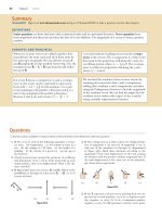
45. ⅷ For a technology project, a student has built a vehicle,
of total mass 6.00 kg, that moves itself. As shown in Figure
P9.45, it runs on two light caterpillar tracks that pass
around four light wheels. A reel is attached to one of the
axles, and a cord originally wound on the reel passes over
a pulley attached to the vehicle to support an elevated
load. After the vehicle is released from rest, the load
descends slowly, unwinding the cord to turn the axle and
make the vehicle move forward. Friction is negligible in
the pulley and axle bearings. The caterpillar tread does
not slip on the wheels or the floor. The reel has a conical
shape so that the load descends at a constant low speed
3 = challenging;
vi
L
u
(b)
(a)
Figure P9.47
48. On a horizontal air track, a glider of mass m carries a ⌫shaped post. The post supports a small dense sphere, also
of mass m, hanging just above the top of the glider on a
cord of length L. The glider and sphere are initially at
rest with the cord vertical. (Fig. P9.47a shows a cart and a
sphere similarly connected.) A constant horizontal force
of magnitude F is applied to the glider, moving it through
displacement x1; then the force is removed. During the
time interval when the force is applied, the sphere moves
through a displacement with horizontal component x2.
(a) Find the horizontal component of the velocity of the
center of mass of the glider-sphere system when the force
is removed. (b) After the force is removed, the glider con-
Figure P9.45
2 = intermediate;
while the vehicle moves horizontally across the floor with
constant acceleration, reaching final velocity 3.00ˆi m/s.
(a) Does the floor impart impulse to the vehicle? If so,
how much? (b) Does the floor do work on the vehicle? If
so, how much? (c) Does it make sense to say that the final
momentum of the vehicle came from the floor? If not,
from where? (d) Does it make sense to say that the final
kinetic energy of the vehicle came from the floor? If not,
from where? (e) Can we say that one particular force
causes the forward acceleration of the vehicle? What does
cause it?
46. ⅷ A 60.0-kg person bends his knees and then jumps
straight up. After his feet leave the floor his motion is
unaffected by air resistance and his center of mass rises by
a maximum of 15.0 cm. Model the floor as completely
solid and motionless. (a) Does the floor impart impulse
to the person? (b) Does the floor do work on the person?
(c) With what momentum does the person leave the
floor? (d) Does it make sense to say that this momentum
came from the floor? Explain. (e) With what kinetic
energy does the person leave the floor? (f) Does it make
sense to say that this energy came from the floor?
Explain.
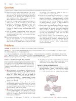
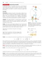
47. ⅷ A particle is suspended from a post on top of a cart by
a light string of length L as shown in Figure P9.47a. The
cart and particle are initially moving to the right at constant speed vi, with the string vertical. The cart suddenly
comes to rest when it runs into and sticks to a bumper as
shown in Figure P9.47b. The suspended particle swings
through an angle u. (a) Show that the original speed of
the cart can be computed from vi ϭ 12gL 11 Ϫ cos u2 .
(b) Find the initial speed implied by L ϭ 1.20 m and u ϭ
35.0°. (c) Is the bumper still exerting a horizontal force
on the cart when the hanging particle is at its maximum
angle from the vertical? At what moment in the observable motion does the bumper stop exerting a horizontal
force on the cart?
Ⅺ = SSM/SG;
ᮡ
= ThomsonNOW;
Ⅵ = symbolic reasoning;
ⅷ = qualitative reasoning
Problems
tinues to move on the track and the sphere swings back
and forth, both without friction. Find an expression for
the largest angle the cord makes with the vertical.
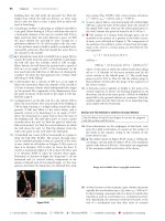
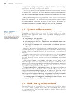
49. ⅷ Sand from a stationary hopper falls onto a moving conveyor belt at the rate of 5.00 kg/s as shown in Figure
P9.49. The conveyor belt is supported by frictionless
rollers. It moves at a constant speed of 0.750 m/sS under
the action of a constant horizontal external force Fext supplied by the motor that drives the belt. Find (a) the sand’s
rate of change of momentum in the horizontal direction,
(b) the force of frictionS exerted by the belt on theSsand,
(c) the external force Fext, (d) the work done by Fext in
1 s, and (e) the kinetic energy acquired by the falling
sand each second due to the change in its horizontal
motion. (f) Why are the answers to (d) and (e) different?
0.750 m/s
a 1t 2 ϭ
265
ve
Tp Ϫ t
(d) Graph the acceleration as a function of time. (e) Show
that the position of the rocket is
x 1t 2 ϭ v e 1Tp Ϫ t 2ln a 1 Ϫ
t
b ϩ ve t
Tp
(f) Graph the position during the burn as a function of
time.
53. ⅷ A rocket for use in deep space is to be capable of
boosting a total load (payload plus rocket frame and
engine) of 3.00 metric tons to a speed of 10 000 m/s.
(a) It has an engine and fuel designed to produce an
exhaust speed of 2 000 m/s. How much fuel plus oxidizer
is required? (b) If a different fuel and engine design
could give an exhaust speed of 5 000 m/s, what amount
of fuel and oxidizer would be required for the same task?
This exhaust speed is 2.50 times higher than that in part
(a). Explain why the required fuel mass is 2.50 times
smaller, or larger than that, or still smaller.
Fext
Figure P9.49
Section 9.8 Rocket Propulsion
50. Model rocket engines are sized by thrust, thrust duration,
and total impulse, among other characteristics. A size C5
model rocket engine has an average thrust of 5.26 N, a
fuel mass of 12.7 g, and an initial mass of 25.5 g. The
duration of its burn is 1.90 s. (a) What is the average
exhaust speed of the engine? (b) This engine is placed in
a rocket body of mass 53.5 g. What is the final velocity of
the rocket if it is fired in outer space? Assume the fuel
burns at a constant rate.
51. ᮡ The first stage of a Saturn V space vehicle consumed fuel
and oxidizer at the rate of 1.50 ϫ 104 kg/s, with an exhaust
speed of 2.60 ϫ 103 m/s. (a) Calculate the thrust produced
by this engine. (b) Find the acceleration the vehicle had
just as it lifted off the launch pad on the Earth, taking the
vehicle’s initial mass as 3.00 ϫ 106 kg. Note: You must
include the gravitational force to solve part (b).
52. Rocket science. A rocket has total mass Mi ϭ 360 kg, including 330 kg of fuel and oxidizer. In interstellar space, it
starts from rest at the position x ϭ 0, turns on its engine
at time t ϭ 0, and puts out exhaust with relative speed ve ϭ
1 500 m/s at the constant rate k ϭ 2.50 kg/s. The fuel will
last for an actual burn time of 330 kg/(2.5 kg/s) ϭ 132 s,
but define a “projected depletion time” as Tp ϭ Mi/k ϭ
360 kg/(2.5 kg/s) ϭ 144 s (which would be the burn time
if the rocket could use its payload and fuel tanks, and
even the walls of the combustion chamber as fuel). (a)
Show that during the burn the velocity of the rocket as a
function of time is given by
v 1t 2 ϭ Ϫv e ln a 1 Ϫ
t
b
Tp
(b) Make a graph of the velocity of the rocket as a function of time for times running from 0 to 132 s. (c) Show
that the acceleration of the rocket is
2 = intermediate;
3 = challenging;
Ⅺ = SSM/SG;
ᮡ
Additional Problems
54. Two gliders are set in motion on an air track. A spring of
force constant k is attached to the back end of the second
S
glider. The first glider, of mass m1, has velocity v1, and the
second glider, of mass m2, moves more slowly, with velocity
S
v2, as shown in Figure P9.54. When m1 collides with the
spring attached to m2 and compresses the spring to its
maximum compression xmax, the velocity of the gliders is
S
S
S
S
v. In terms of v1, v2, m1, m2, and k, find (a) the velocity v
at maximum compression, (b) the maximum compression xmax, and (c) the velocity of each glider after m1 has
lost contact with the spring.
v2
k
m2
v1
m1
Figure P9.54
55. An 80.0-kg astronaut is taking a space walk to work on the
engines of his ship, which is drifting through space with a
constant velocity. The astronaut, wishing to get a better
view of the Universe, pushes against the ship and much
later finds himself 30.0 m behind the ship. Without a
thruster or tether, the only way to return to the ship is to
throw his 0.500-kg wrench directly away from the ship. If
he throws the wrench with a speed of 20.0 m/s relative to
the ship, after what time interval does the astronaut reach
the ship?
56. ⅷ An aging Hollywood actor (mass 80.0 kg) has been
cloned, but the genetic replica is far from perfect. The
clone has a different mass m, his stage presence is poor,
= ThomsonNOW;
Ⅵ = symbolic reasoning;
ⅷ = qualitative reasoning
266
Chapter 9
Linear Momentum and Collisions
and he uses foul language. The clone, serving as the
actor’s stunt double, stands on the brink of a cliff 36.0 m
high, next to a sturdy tree. The actor stands on top of a
Humvee, 1.80 m above the level ground, holding a taut
rope tied to a tree branch directly above the clone. When
the director calls “action,” the actor starts from rest and
swings down on the rope without friction. The actor is
momentarily hidden from the camera at the bottom of
the arc, where he undergoes an elastic head-on collision
with the clone, sending him over the cliff. Cursing vilely,
the clone falls freely into the ocean below. The actor is
prosecuted for making an obscene clone fall, and you are
called as an expert witness at the sensational trial.
(a) Find the horizontal component R of the clone’s displacement as it depends on m. Evaluate R (b) for m ϭ
79.0 kg and (c) for m ϭ 81.0 kg. (d) What value of m
gives a range of 30.0 m? (e) What is the maximum possible value for R, and (f) to what value of m does it correspond? What are (g) the minimum values of R and
(h) the corresponding value of m? (i) For the actor–clone–
Earth system, is mechanical energy conserved throughout
the action sequence? Is this principle sufficient to solve
the problem? Explain. (j) For the same system, is momentum conserved? Explain how this principle is used.
(k) What If? Show that R does not depend on the value of
the gravitational acceleration. Is this result remarkable?
State how one might make sense of it.
57. A bullet of mass m is fired into a block of mass M initially
at rest at the edge of a frictionless table of height h (Fig.
P9.57). The bullet remains in the block, and after impact
the block lands a distance d from the bottom of the table.
Determine the initial speed of the bullet.
59.
60.
61.
m
M
h
d
Figure P9.57
58. A small block of mass m1 ϭ 0.500 kg is released from rest
at the top of a curve-shaped, frictionless wedge of mass
m2 ϭ 3.00 kg, which sits on a frictionless horizontal surface as shown in Figure P9.58a. When the block leaves the
wedge, its velocity is measured to be 4.00 m/s to the right
as shown in the figure. (a) What is the velocity of the
m1
h
v2
m2
m2
(a)
4.00 m/s
62.
wedge after the block reaches the horizontal surface?
(b) What is the height h of the wedge?
ⅷ A 0.500-kg sphere moving with a velocity given by
ˆ 2 m>s strikes another sphere of
12.00ˆi Ϫ 3.00ˆj ϩ 1.00k
mass 1.50 kg that is moving with an initial velocity
ˆ 2 m>s. (a) The velocity of
of 1Ϫ1.00ˆi ϩ 2.00ˆj Ϫ 3.00k
the 0.500-kg sphere after the collision is given by
ˆ 2 m>s. Find the final velocity of
1Ϫ1.00ˆi ϩ 3.00ˆj Ϫ 8.00k
the 1.50-kg sphere and identify the kind of collision (elastic, inelastic, or perfectly inelastic). (b) Now assume the
velocity of the 0.500-kg sphere after the collision is
ˆ 2 m>s. Find the final velocity
1Ϫ0.250ˆi ϩ 0.750ˆj Ϫ 2.00k
of the 1.50-kg sphere and identify the kind of collision.
(c) What If? Take the velocity of the 0.500-kg sphere after
ˆ 2 m>s. Find the
the collision as 1Ϫ1.00ˆi ϩ 3.00ˆj ϩ ak
value of a and the velocity of the 1.50-kg sphere after an
elastic collision.
A 75.0-kg firefighter slides down a pole while a constant
friction force of 300 N retards her motion. A horizontal
20.0-kg platform is supported by a spring at the bottom of
the pole to cushion the fall. The firefighter starts from
rest 4.00 m above the platform, and the spring constant is
4 000 N/m. Find (a) the firefighter’s speed immediately
before she collides with the platform and (b) the maximum distance the spring is compressed. Assume the friction force acts during the entire motion.
ⅷ George of the Jungle, with mass m, swings on a light
vine hanging from a stationary tree branch. A second vine
of equal length hangs from the same point, and a gorilla
of larger mass M swings in the opposite direction on it.
Both vines are horizontal when the primates start from
rest at the same moment. George and the gorilla meet at
the lowest point of their swings. Each is afraid that one
vine will break, so they grab each other and hang on.
They swing upward together, reaching a point where the
vines make an angle of 35.0° with the vertical. (a) Find
the value of the ratio m/M. (b) What If? Try the following
experiment at home. Tie a small magnet and a steel screw
to opposite ends of a string. Hold the center of the string
fixed to represent the tree branch, and reproduce a
model of the motions of George and the gorilla. What
changes in your analysis will make it apply to this situation? What If? Next assume the magnet is strong so that it
noticeably attracts the screw over a distance of a few centimeters. Then the screw will be moving faster immediately before it sticks to the magnet. Does this extra magnet strength make a difference?
ⅷ A student performs a ballistic pendulum experiment
using an apparatus similar to that shown in Figure 9.9b.
She obtains the following average data: h ϭ 8.68 cm, m1 ϭ
68.8 g, and m2 ϭ 263 g. The symbols refer to the quantities in Figure 9.9a. (a) Determine the initial speed v1A of
the projectile. (b) The second part of her experiment is
to obtain v1A by firing the same projectile horizontally
(with the pendulum removed from the path) and measuring its final horizontal position x and distance of fall y
(Fig. P9.62). Show that the initial speed of the projectile
is related to x and y by the equation
(b)
v1A ϭ
Figure P9.58
2 = intermediate;
3 = challenging;
Ⅺ = SSM/SG;
ᮡ
= ThomsonNOW;
x
22y>g
Ⅵ = symbolic reasoning;
ⅷ = qualitative reasoning
Problems
267
67. A 5.00-g bullet moving with an initial speed of 400 m/s is
fired into and passes through a 1.00-kg block as shown in
Figure P9.67. The block, initially at rest on a frictionless,
horizontal surface, is connected to a spring with force
constant 900 N/m. The block moves 5.00 cm to the right
after impact. Find (a) the speed at which the bullet
emerges from the block and (b) the mechanical energy
converted into internal energy in the collision.
v1A
y
x
Figure P9.62
400 m/s
What numerical value does she obtain for v1A based on
her measured values of x ϭ 257 cm and y ϭ 85.3 cm?
What factors might account for the difference in this
value compared with that obtained in part (a)?
63. ⅷ Lazarus Carnot, an artillery general, managed the military draft for Napoleon. Carnot used a ballistic pendulum
to measure the firing speeds of cannonballs. In the symbols defined in Example 9.6, he proved that the ratio
of the kinetic energy immediately after the collision to
the kinetic energy immediately before is m1/(m1ϩm2).
(a) Carry out the proof yourself. (b) If the cannonball has
mass 9.60 kg and the block (a tree trunk) has mass 214 kg,
what fraction of the original energy remains mechanical
after the collision? (c) What is the ratio of the momentum immediately after the collision to the momentum
immediately before? (d) A student believes that such a
large loss of mechanical energy must be accompanied by
at least a small loss of momentum. How would you convince this student of the truth? General Carnot’s son Sadi
was the second most important engineer in the history of
ideas; we will study his work in Chapter 22.
64. ⅷ Pursued by ferocious wolves, you are in a sleigh with no
horses, gliding without friction across an ice-covered lake.
You take an action described by these equations:
1270 kg2 17.50 m>s 2 ˆi ϭ 115.0 kg2 1Ϫv 1fˆi 2 ϩ 1255 kg2 1v 2fˆi 2
v 1f ϩ v 2f ϭ 8.00 m>s
(a) Complete the statement of the problem, giving the
data and identifying the unknowns. (b) Find the values of
v1f and v2f. (c) Find the work you do.
65. Review problem. A light spring of force constant
3.85 N/m is compressed by 8.00 cm and held between a
0.250-kg block on the left and a 0.500-kg block on the
right. Both blocks are at rest on a horizontal surface. The
blocks are released simultaneously so that the spring
tends to push them apart. Find the maximum velocity
each block attains if the coefficient of kinetic friction
between each block and the surface is (a) 0, (b) 0.100,
and (c) 0.462. Assume the coefficient of static friction is
greater than the coefficient of kinetic friction in every
case.
66. Consider as a system the Sun with the Earth in a circular
orbit around it. Find the magnitude of the change in the
velocity of the Sun relative to the center of mass of the
system over a 6-month period. Ignore the influence of
other celestial objects. You may obtain the necessary astronomical data from the endpapers of the book.
2 = intermediate;
3 = challenging;
Ⅺ = SSM/SG;
ᮡ
5.00 cm
v
Figure P9.67
68. ⅷ Review problem. There are (one can say) three
coequal theories of motion: Newton’s second law, stating
that the total force on a particle causes its acceleration;
the work–kinetic energy theorem, stating that the total
work on a particle causes its change in kinetic energy; and
the impulse–momentum theorem, stating that the total
impulse on a particle causes its change in momentum. In
this problem, you compare predictions of the three theories in one particular case. A 3.00-kg object has velocity
7.00ˆj m>s. Then, a total force 12.0ˆi N acts on the object
for 5.00 s. (a) Calculate the object’s final velocity, using
the impulse–momentum theorem. (b) Calculate its accelS
S
S
eration from a ϭ S1vf Ϫ vi 2>¢t. (c) Calculate its acceleraS
tion from a ϭ © F>m. (d) Find the object’s vector disS
S
S
placement from ¢ r ϭ vi t Sϩ 12 at 2. (e) Find the work done
S
#
on the object from W ϭ F ¢r . (f) Find the final kinetic
1
1 S #S
2
energy from 2mv f ϭ 2 mvf vf. (g) Find the final kinetic
energy from 12mv i 2 ϩ W. (h) State the result of comparing
the answers to parts b and c, and the answers to parts f
and g.
69. A chain of length L and total mass M is released from rest
with its lower end just touching the top of a table as
shown in Figure P9.69a. Find the force exerted by the
table on the chain after the chain has fallen through a
distance x as shown in Figure P9.69b. (Assume each link
comes to rest the instant it reaches the table.)
= ThomsonNOW;
x
L
L Ϫx
(a)
(b)
Figure P9.69
Ⅵ = symbolic reasoning;
ⅷ = qualitative reasoning
268
Chapter 9
Linear Momentum and Collisions
Answers to Quick Quizzes
9.1 (d). Two identical objects (m1 ϭ m2) traveling at the same
speed (v1 ϭ v2) have the same kinetic energies and the
same magnitudes of momentum. It also is possible, however, for particular combinations of masses and velocities
to satisfy K1 ϭ K2 but not p1 ϭ p2. For example, a 1-kg
object moving at 2 m/s has the same kinetic energy as a
4-kg object moving at 1 m/s, but the two clearly do not
have the same momenta. Because we have no information
about masses and speeds, we cannot choose among (a),
(b), or (c).
9.2 (b), (c), (a). The slower the ball, the easier it is to catch. If
the momentum of the medicine ball is the same as the
momentum of the baseball, the speed of the medicine
ball must be 1/10 the speed of the baseball because the
medicine ball has 10 times the mass. If the kinetic energies are the same, the speed of the medicine ball must be
1> 110 the speed of the baseball because of the squared
speed term in the equation for K. The medicine ball is
hardest to catch when it has the same speed as the baseball.
9.3 (i), (c), (e). Object 2 has a greater acceleration because of
its smaller mass. Therefore, it travels the distance d in a
shorter time interval. Even though the force applied to
objects 1 and 2 is the same, the change in momentum is
less for object 2 because ⌬t is smaller. The work W ϭ Fd
done on both objects is the same because both F and d
are the same in the two cases. Therefore, K1 ϭ K2.
(ii), (b), (d). The same impulse is applied to both objects,
so they experience the same change in momentum.
Object 2 has a larger acceleration due to its smaller mass.
Therefore, the distance that object 2 covers in the time
interval is larger than that for object 1. As a result, more
work is done on object 2 and K2 Ͼ K1.
9.4 (a) All three are the same. Because the passenger is
brought from the car’s initial speed to a full stop, the
change in momentum (equal to the impulse) is the same
regardless of what stops the passenger. (b) Dashboard,
seat belt, air bag. The dashboard stops the passenger very
quickly in a front-end collision, resulting in a very large
force. The seat belt takes somewhat more time, so the
force is smaller. Used along with the seat belt, the air bag
can extend the passenger’s stopping time further, notably
for his head, which would otherwise snap forward.
9.5 (a). If all the initial kinetic energy is transformed or transferred away from the system, nothing is moving after the
collision. Consequently, the final momentum of the system is necessarily zero and the initial momentum of the
system must therefore be zero. Although (b) and (d)
together would satisfy the conditions, neither one alone
does.
9.6 (b). Because momentum of the two-ball system is conS
S
S
served, pTi ϩ 0 ϭ pTf ϩ pB. Because the table-tennis ball
bounces back from the much more massive bowling ball
S
S
with approximately the same speed, pTf ϭ ϪpTi. As a conS
S
sequence, pB ϭ 2pTi. Kinetic energy can be expressed as
K ϭ p 2/2m. Because of the much larger mass of the bowling ball, its kinetic energy is much smaller than that of
the table-tennis ball.
9.7 (b). The piece with the handle will have less mass than the
piece made up of the end of the bat. To see why, take the
origin of coordinates as the center of mass before the bat
was cut. Replace each cut piece by a small sphere located
at each piece’s center of mass. The sphere representing
the handle piece is farther from the origin, but the product of less mass and greater distance balances the product
of greater mass and less distance for the end piece as
shown.
9.8 (i), (a). This effect is the same one as the swimmer diving
off the raft that we just discussed. The vessel–passengers
system is isolated. If the passengers all start running one
way, the speed of the vessel increases (a small amount!)
the other way. (ii), (b). Once they stop running, the
momentum of the system is the same as it was before they
started running; you cannot change the momentum of an
isolated system by means of internal forces. In case you
are thinking that the passengers could run to the stern
repeatedly to take advantage of the speed increase while
they are running, remember that they will slow the ship
down every time they return to the bow!
10.1 Angular Position,
Velocity, and
Acceleration
10.5 Calculation of Moments
of Inertia
10.2 Rotational Kinematics:
The Rigid Object Under
Constant Angular
Acceleration
10.7 The Rigid Object Under
a Net Torque
10.6 Torque
10.8 Energy Considerations
in Rotational Motion
10.3 Angular and
Translational Quantities
10.9 Rolling Motion of a
Rigid Object
10.4 Rotational Kinetic
Energy
The Malaysian pastime of gasing involves the spinning of tops that can
have masses up to 5 kg. Professional spinners can spin their tops so that
they might rotate for more than an hour before stopping. We will study the
rotational motion of objects such as these tops in this chapter. (Courtesy
Tourism Malaysia)
10
Rotation of a Rigid Object
About a Fixed Axis
When an extended object such as a wheel rotates about its axis, the motion cannot
be analyzed by modeling the object as a particle because at any given time different parts of the object have different linear velocities and linear accelerations. We
can, however, analyze the motion of an extended object by modeling it as a collection of particles, each of which has its own linear velocity and linear acceleration.
In dealing with a rotating object, analysis is greatly simplified by assuming the
object is rigid. A rigid object is one that is nondeformable; that is, the relative locations of all particles of which the object is composed remain constant. All real
objects are deformable to some extent; our rigid-object model, however, is useful
in many situations in which deformation is negligible.
r
O
P
(a)
P
r
O
10.1
Angular Position, Velocity,
and Acceleration
Figure 10.1 illustrates an overhead view of a rotating compact disc, or CD. The
disc rotates about a fixed axis perpendicular to the plane of the figure and passing
through the center of the disc at O. A small element of the disc modeled as a particle at P is at a fixed distance r from the origin and rotates about it in a circle of
radius r. (In fact, every particle on the disc undergoes circular motion about O.) It
is convenient to represent the position of P with its polar coordinates (r, u), where
Reference
line
s
u
Reference
line
(b)
Figure 10.1 A compact disc rotating
about a fixed axis through O perpendicular to the plane of the figure.
(a) To define angular position for the
disc, a fixed reference line is chosen.
A particle at P is located at a distance
r from the rotation axis at O. (b) As
the disc rotates, a particle at P moves
through an arc length s on a circular
path of radius r.
269
270
Chapter 10
Rotation of a Rigid Object About a Fixed Axis
r is the distance from the origin to P and u is measured counterclockwise from some
reference line fixed in space as shown in Figure 10.1a. In this representation, the
angle u changes in time while r remains constant. As the particle moves along the
circle from the reference line, which is at angle u ϭ 0, it moves through an arc of
length s as in Figure 10.1b. The arc length s is related to the angle u through the
relationship
s ϭ ru
uϭ
In rotational equations, you must
use angles expressed in radians.
Don’t fall into the trap of using
angles measured in degrees in
rotational equations.
u 1rad 2 ϭ
y
Ꭾ,t f
Ꭽ,ti
uf
ui
x
O
Figure 10.2 A particle on a rotating
rigid object moves from Ꭽ to Ꭾ
along the arc of a circle. In the time
interval ⌬t ϭ tf Ϫ ti, the radial line of
length r moves through an angular
displacement ⌬u ϭ uf Ϫ ui.
Average angular speed
s
r
(10.1b)
Because u is the ratio of an arc length and the radius of the circle, it is a pure
number. Usually, however, we give u the artificial unit radian (rad), where one
radian is the angle subtended by an arc length equal to the radius of the arc.
Because the circumference of a circle is 2pr, it follows from Equation 10.1b that
360° corresponds to an angle of (2pr/r) rad ϭ 2p rad. Hence, 1 rad ϭ 360°/2p Ϸ
57.3°. To convert an angle in degrees to an angle in radians, we use that p rad ϭ
180°, so
PITFALL PREVENTION 10.1
Remember the Radian
r
(10.1a)
ᮣ
p
u 1deg 2
180°
For example, 60° equals p/3 rad and 45° equals p/4 rad.
Because the disc in Figure 10.1 is a rigid object, as the particle moves through
an angle u from the reference line, every other particle on the object rotates
through the same angle u. Therefore, we can associate the angle U with the entire
rigid object as well as with an individual particle, which allows us to define the
angular position of a rigid object in its rotational motion. We choose a reference
line on the object, such as a line connecting O and a chosen particle on the
object. The angular position of the rigid object is the angle u between this reference line on the object and the fixed reference line in space, which is often chosen as the x axis. Such identification is similar to the way we define the position of
an object in translational motion as the distance x between the object and the reference position, which is the origin, x ϭ 0.
As the particle in question on our rigid object travels from position Ꭽ to position Ꭾ in a time interval ⌬t as in Figure 10.2, the reference line fixed to the object
sweeps out an angle ⌬u ϭ uf Ϫui. This quantity ⌬u is defined as the angular displacement of the rigid object:
¢u ϵ u f Ϫ u i
The rate at which this angular displacement occurs can vary. If the rigid object
spins rapidly, this displacement can occur in a short time interval. If it rotates
slowly, this displacement occurs in a longer time interval. These different rotation
rates can be quantified by defining the average angular speed vavg (Greek letter
omega) as the ratio of the angular displacement of a rigid object to the time interval ⌬t during which the displacement occurs:
vavg ϵ
uf Ϫ ui
tf Ϫ ti
ϭ
¢u
¢t
(10.2)
In analogy to linear speed, the instantaneous angular speed v is defined as the
limit of the average angular speed as ⌬t approaches zero:
Instantaneous angular speed
ᮣ
v ϵ lim
¢tS0
¢u
du
ϭ
¢t
dt
(10.3)
Angular speed has units of radians per second (rad/s), which can be written as sϪ1
because radians are not dimensional. We take v to be positive when u is increasing
(counterclockwise motion in Figure 10.2) and negative when u is decreasing
(clockwise motion in Figure 10.2).
Section 10.1
Angular Position, Velocity, and Acceleration
271
Quick Quiz 10.1 A rigid object rotates in a counterclockwise sense around a
fixed axis. Each of the following pairs of quantities represents an initial angular
position and a final angular position of the rigid object. (i) Which of the sets can
only occur if the rigid object rotates through more than 180°? (a) 3 rad, 6 rad
(b) Ϫ1 rad, 1 rad (c) 1 rad, 5 rad (ii) Suppose the change in angular position for
each of these pairs of values occurs in 1 s. Which choice represents the lowest average angular speed?
If the instantaneous angular speed of an object changes from vi to vf in the
time interval ⌬t, the object has an angular acceleration. The average angular acceleration aavg (Greek letter alpha) of a rotating rigid object is defined as the ratio of
the change in the angular speed to the time interval ⌬t during which the change
in the angular speed occurs:
a avg ϵ
vf Ϫ vi
tf Ϫ ti
ϭ
¢v
¢t
(10.4)
ᮤ
Average angular
acceleration
ᮤ
Instantaneous angular
acceleration
In analogy to linear acceleration, the instantaneous angular acceleration is
defined as the limit of the average angular acceleration as ⌬t approaches zero:
¢v
dv
ϭ
dt
¢tS0 ¢t
a ϵ lim
(10.5)
Angular acceleration has units of radians per second squared (rad/s2), or simply sϪ2. Notice that a is positive when a rigid object rotating counterclockwise is
speeding up or when a rigid object rotating clockwise is slowing down during
some time interval.
When a rigid object is rotating about a fixed axis, every particle on the object
rotates through the same angle in a given time interval and has the same angular
speed and the same angular acceleration. That is, the quantities u, v, and a characterize the rotational motion of the entire rigid object as well as individual particles
in the object.
Angular position (u), angular speed (v), and angular acceleration (a) are analogous to translational position (x), translational speed (v), and translational acceleration (a). The variables u, v, and a differ dimensionally from the variables x, v,
and a only by a factor having the unit of length. (See Section 10.3.)
We have not specified any direction for angular speed and angular acceleration.
Strictly speaking, v and a are the magnitudes of the angular velocity and the anguS
S
lar acceleration vectors1 V and A, respectively, and they should always be positive.
Because we are considering rotation about a fixed axis, however, we can use nonvector notation and indicate the vectors’ directions by assigning a positive or negative sign to v and a as discussed earlier with regard to Equations 10.3 and 10.5.
For rotation about a fixed axis, the only direction that uniquely specifies the rotational motion is the direction along the axis of rotation. Therefore, the directions
S
S
of V and A are along this axis. If a particle rotates in the xy plane as in Figure 10.2,
S
the direction of V for the particle is out of the plane of the diagram when the
rotation is counterclockwise and into the plane of the diagram when the rotation
is clockwise. To illustrate this convention, it is convenient to use the right-hand rule
demonstrated in Figure 10.3. When the four fingers of the right hand are wrapped
in the direction of rotation, the extended right thumb points in the direction of
S
S
S
S
V. The direction of A follows from its definition A ϵ dV>dt. It is in the same direcS
S
tion as V if the angular speed is increasing in time, and it is antiparallel to V if the
angular speed is decreasing in time.
PITFALL PREVENTION 10.2
Specify Your Axis
In solving rotation problems, you
must specify an axis of rotation.
This new feature does not exist in
our study of translational motion.
The choice is arbitrary, but once
you make it, you must maintain
that choice consistently throughout
the problem. In some problems,
the physical situation suggests a
natural axis, such as the center of
an automobile wheel. In other
problems, there may not be an
obvious choice, and you must exercise judgment.
v
v
1
Although we do not verify it here, the instantaneous angular velocity and instantaneous angular acceleration are vector quantities, but the corresponding average values are not because angular displacements do not add as vector quantities for finite rotations.
Figure 10.3 The right-hand rule for
determining the direction of the
angular velocity vector.
272
Chapter 10
Rotation of a Rigid Object About a Fixed Axis
10.2
Rotational Kinematics: The Rigid Object
Under Constant Angular Acceleration
When a rigid object rotates about a fixed axis, it often undergoes a constant angular acceleration. Therefore, we generate a new analysis model for rotational
motion called the rigid object under constant angular acceleration. This model is
the rotational analog to the particle under constant acceleration model. We
develop kinematic relationships for this model in this section. Writing Equation
10.5 in the form dv ϭ a dt and integrating from ti ϭ 0 to tf ϭ t gives
Rotational kinematic
equations
vf ϭ vi ϩ at¬1for constant a2
ᮣ
PITFALL PREVENTION 10.3
Just Like Translation?
Equations 10.6 to 10.9 and Table
10.1 suggest that rotational kinematics is just like translational kinematics. That is almost true, with
two key differences. (1) In rotational kinematics, you must specify
a rotation axis (per Pitfall Prevention 10.2). (2) In rotational
motion, the object keeps returning
to its original orientation; therefore, you may be asked for the
number of revolutions made by a
rigid object. This concept has no
meaning in translational motion.
(10.6)
where vi is the angular speed of the rigid object at time t ϭ 0. Equation 10.6
allows us to find the angular speed vf of the object at any later time t. Substituting
Equation 10.6 into Equation 10.3 and integrating once more, we obtain
u f ϭ u i ϩ vit ϩ 12at 2
1for constant a2
(10.7)
where ui is the angular position of the rigid object at time t ϭ 0. Equation 10.7
allows us to find the angular position uf of the object at any later time t. Eliminating t from Equations 10.6 and 10.7 gives
v f 2 ϭ v i 2 ϩ 2a 1u f Ϫ u i 2¬1for constant a2
(10.8)
This equation allows us to find the angular speed vf of the rigid object for any
value of its angular position uf . If we eliminate a between Equations 10.6 and 10.7,
we obtain
u f ϭ u i ϩ 12 1vi ϩ vf 2t
1for constant a 2
(10.9)
Notice that these kinematic expressions for the rigid object under constant
angular acceleration are of the same mathematical form as those for a particle
under constant acceleration (Chapter 2). They can be generated from the equations for translational motion by making the substitutions x S u, v S v, and a S a.
Table 10.1 compares the kinematic equations for rotational and translational
motion.
Quick Quiz 10.2 Consider again the pairs of angular positions for the rigid
object in Quick Quiz 10.1. If the object starts from rest at the initial angular position, moves counterclockwise with constant angular acceleration, and arrives at the
final angular position with the same angular speed in all three cases, for which
choice is the angular acceleration the highest?
TABLE 10.1
Kinematic Equations for Rotational
and Translational Motion Under
Constant Acceleration
Rotational Motion
About a Fixed Axis
Translational Motion
vf ϭ vi ϩ at
vf ϭ vi ϩ at
uf ϭ u i ϩ v i t ϩ
vf2 ϭ vi2 ϩ 2a(uf Ϫ ui )
uf ϭ ui ϩ 12 (vi ϩ vf )t
1
2
2 at
xf ϭ xi ϩ vi t ϩ 12 at 2
vf2 ϭ vi2 ϩ 2a(xf Ϫ xi )
xf ϭ xi ϩ 12 (vi ϩ vf )t
Section 10.3
E XA M P L E 1 0 . 1
Angular and Translational Quantities
273
Rotating Wheel
A wheel rotates with a constant angular acceleration of 3.50 rad/s2.
(A) If the angular speed of the wheel is 2.00 rad/s at ti ϭ 0, through what angular displacement does the wheel
rotate in 2.00 s?
SOLUTION
Conceptualize Look again at Figure 10.1. Imagine that the compact disc rotates with its angular speed increasing at
a constant rate. You start your stopwatch when the disc is rotating at 2.00 rad/s. This mental image is a model for the
motion of the wheel in this example.
Categorize The phrase “with a constant angular acceleration” tells us to use the rigid object under constant angular acceleration model.
Analyze Arrange Equation 10.7 so that it expresses the
angular displacement of the object:
Substitute the known values to find the angular displacement at t ϭ 2.00 s:
¢u ϭ u f Ϫ u i ϭ vit ϩ 12at 2
¢u ϭ 12.00 rad>s2 12.00 s2 ϩ 12 13.50 rad>s2 2 12.00 s 2 2
ϭ 11.0 rad ϭ 111.0 rad 2 157.3°>rad 2 ϭ 630°
(B) Through how many revolutions has the wheel turned during this time interval?
SOLUTION
Multiply the angular displacement found in part (A) by
a conversion factor to find the number of revolutions:
¢u ϭ 630° a
1 rev
b ϭ 1.75 rev
360°
(C) What is the angular speed of the wheel at t ϭ 2.00 s?
SOLUTION
Use Equation 10.6 to find the angular speed at
t ϭ 2.00 s:
Finalize
vf ϭ vi ϩ at ϭ 2.00 rad>s ϩ 13.50 rad>s2 2 12.00 s 2
ϭ 9.00 rad>s
We could also obtain this result using Equation 10.8 and the results of part (A). (Try it!)
What If? Suppose a particle moves along a straight line with a constant acceleration of 3.50 m/s2. If the velocity of
the particle is 2.00 m/s at ti ϭ 0, through what displacement does the particle move in 2.00 s? What is the velocity of
the particle at t ϭ 2.00 s?
Answer Notice that these questions are translational analogs to parts (A) and (C) of the original problem. The
mathematical solution follows exactly the same form. For the displacement,
¢x ϭ x f Ϫ x i ϭ v it ϩ 12at 2
ϭ 12.00 m>s2 12.00 s 2 ϩ 12 13.50 m>s2 2 12.00 s 2 2 ϭ 11.0 m
and for the velocity,
vf ϭ vi ϩ at ϭ 2.00 m>s ϩ 13.50 m>s2 2 12.00 s 2 ϭ 9.00 m>s
There is no translational analog to part (B) because translational motion under constant acceleration is not repetitive.
10.3
Angular and Translational Quantities
In this section, we derive some useful relationships between the angular speed and
acceleration of a rotating rigid object and the translational speed and acceleration
of a point in the object. To do so, we must keep in mind that when a rigid object
274
Chapter 10
Rotation of a Rigid Object About a Fixed Axis
rotates about a fixed axis as in Active Figure 10.4, every particle of the object
moves in a circle whose center is on the axis of rotation.
Because point P in Active Figure 10.4 moves in a circle, the translational velocity
S
vector v is always tangent to the circular path and hence is called tangential velocity.
The magnitude of the tangential velocity of the point P is by definition the tangential speed v ϭ ds/dt, where s is the distance traveled by this point measured along
the circular path. Recalling that s ϭ r u (Eq. 10.1a) and noting that r is constant,
we obtain
y
v
P
s
r
u
x
O
vϭ
ACTIVE FIGURE 10.4
As a rigid object rotates about the
fixed axis through O, the point P has a
S
tangential velocity v that is always tangent to the circular path of radius r.
Sign in at www.thomsonedu.com and
go to ThomsonNOW to move point P
and observe the tangential velocity as
the object rotates.
Because du/dt ϭ v (see Eq. 10.3), it follows that
v ϭ rv
ᮣ
dv
dv
ϭr
dt
dt
at ϭ ra
(10.11)
That is, the tangential component of the translational acceleration of a point on a
rotating rigid object equals the point’s perpendicular distance from the axis of
rotation multiplied by the angular acceleration.
In Section 4.4, we found that a point moving in a circular path undergoes a
radial acceleration ar directed toward the center of rotation and whose magnitude
is that of the centripetal acceleration v2/r (Fig. 10.5). Because v ϭ r v for a point
P on a rotating object, we can express the centripetal acceleration at that point in
terms of angular speed as
ac ϭ
y
v2
ϭ rv 2
r
(10.12)
The total acceleration vector at the point is a ϭ at ϩ ar , where the magnitude
S
S
of ar is the centripetal acceleration ac . Because a is a vector having a radial and a
S
tangential component, the magnitude of a at the point P on the rotating rigid
object is
S
at
P
a
ar
O
(10.10)
That is, the tangential speed of a point on a rotating rigid object equals the perpendicular distance of that point from the axis of rotation multiplied by the angular speed. Therefore, although every point on the rigid object has the same angular speed, not every point has the same tangential speed because r is not the same
for all points on the object. Equation 10.10 shows that the tangential speed of a
point on the rotating object increases as one moves outward from the center of
rotation, as we would intuitively expect. For example, the outer end of a swinging
golf club moves much faster than the handle.
We can relate the angular acceleration of the rotating rigid object to the tangential acceleration of the point P by taking the time derivative of v:
at ϭ
Relation between tangential
and angular acceleration
ds
du
ϭr
dt
dt
S
S
a ϭ 2at 2 ϩ ar2 ϭ 2r2a 2 ϩ r2v 4 ϭ r 2a 2 ϩ v 4
(10.13)
x
Figure 10.5 As a rigid object rotates
about a fixed axis through O, the
point P experiences a tangential component of translational acceleration
at and a radial component of translational acceleration ar. The total accelS
S
S
eration of this point is a ϭ at ϩ ar .
Quick Quiz 10.3 Alex and Brian are riding on a merry-go-round. Alex rides on
a horse at the outer rim of the circular platform, twice as far from the center of
the circular platform as Brian, who rides on an inner horse. (i) When the merrygo-round is rotating at a constant angular speed, what is Alex’s angular speed?
(a) twice Brian’s (b) the same as Brian’s (c) half of Brian’s (d) impossible to
determine (ii) When the merry-go-round is rotating at a constant angular speed,
describe Alex’s tangential speed from the same list of choices.
Section 10.3
275
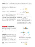
CD Player
On a compact disc (Fig. 10.6), audio information is stored digitally in a series of
pits and flat areas on the surface of the disc. The alternations between pits and
flat areas on the surface represent binary ones and zeroes to be read by the CD
player and converted back to sound waves. The pits and flat areas are detected by
a system consisting of a laser and lenses. The length of a string of ones and zeroes
representing one piece of information is the same everywhere on the disc,
whether the information is near the center of the disc or near its outer edge. So
that this length of ones and zeroes always passes by the laser–lens system in the
same time interval, the tangential speed of the disc surface at the location of the
lens must be constant. According to Equation 10.10, the angular speed must
therefore vary as the laser–lens system moves radially along the disc. In a typical
CD player, the constant speed of the surface at the point of the laser–lens system
is 1.3 m/s.
23 mm
58 mm
George Semple
E XA M P L E 1 0 . 2
Angular and Translational Quantities
Figure 10.6
pact disc.
(Example 10.2) A com-
(A) Find the angular speed of the disc in revolutions per minute when information is being read from the innermost
first track (r ϭ 23 mm) and the outermost final track (r ϭ 58 mm).
SOLUTION
Conceptualize Figure 10.6 shows a photograph of a compact disc. Trace your finger around the circle marked “23 mm”
in a time interval of about 3 s. Now trace your finger around the circle marked “58 mm” in the same time interval.
Notice how much faster your finger is moving relative to the page around the larger circle. If your finger represents
the laser reading the disc, it is moving over the surface of the disc much faster for the outer circle than for the inner
circle.
Categorize This part of the example is categorized as a simple substitution problem. In later parts, we will need to
identify analysis models.
Use Equation 10.10 to find the angular speed that
gives the required tangential speed at the position of
the inner track:
vi ϭ
Do the same for the outer track:
vf ϭ
1.3 m>s
v
ϭ 57 rad>s
ϭ
ri
2.3 ϫ 10Ϫ2 m
ϭ 157 rad>s2 a
1 rev
60 s
ba
b ϭ 5.4 ϫ 102 rev>min
2p rad
1 min
1.3 m>s
v
ϭ
ϭ 22 rad>s ϭ 2.1 ϫ 102 rev>min
rf
5.8 ϫ 10Ϫ2 m
The CD player adjusts the angular speed v of the disc within this range so that information moves past the objective
lens at a constant rate.
(B) The maximum playing time of a standard music disc is 74 min and 33 s. How many revolutions does the disc
make during that time?
SOLUTION
Categorize From part (A), the angular speed decreases as the disc plays. Let us assume it decreases steadily, with a
constant. We can then use the rigid object under constant angular acceleration model.
Analyze If t ϭ 0 is the instant the disc begins rotating, with angular speed of 57 rad/s, the final value of the time t
is (74 min)(60 s/min) ϩ 33 s ϭ 4 473 s. We are looking for the angular displacement ⌬u during this time interval.
Use Equation 10.9 to find the angular displacement
of the disc at t ϭ 4 473 s:
Convert this angular displacement to revolutions:
¢u ϭ u f Ϫ u i ϭ 12 1vi ϩ vf 2t
ϭ 12 157 rad>s ϩ 22 rad>s2 14 473 s 2 ϭ 1.8 ϫ 105 rad
¢u ϭ 11.8 ϫ 105 rad2 a
1 rev
b ϭ 2.8 ϫ 104 rev
2p rad
276
Chapter 10
Rotation of a Rigid Object About a Fixed Axis
(C) What is the angular acceleration of the compact disc over the 4 473-s time interval?
SOLUTION
Categorize We again model the disc as a rigid object under constant angular acceleration. In this case, Equation
10.6 gives the value of the constant angular acceleration. Another approach is to use Equation 10.4 to find the average angular acceleration. In this case, we are not assuming that the angular acceleration is constant. The answer is
the same from both equations; only the interpretation of the result is different.
Analyze Use Equation 10.6 to find the angular
acceleration:
aϭ
vf Ϫ vi
t
22 rad>s Ϫ 57 rad>s
ϭ
4 473 s
ϭ Ϫ7.8 ϫ 10Ϫ3 rad>s2
Finalize The disc experiences a very gradual decrease in its rotation rate, as expected from the long time interval
required for the angular speed to change from the initial value to the final value. In reality, the angular acceleration
of the disc is not constant. Problem 20 allows you to explore the actual time behavior of the angular acceleration.
z axis
10.4
v
Rotational Kinetic Energy
In Chapter 7, we defined the kinetic energy of an object as the energy associated
with its motion through space. An object rotating about a fixed axis remains stationary in space, so there is no kinetic energy associated with translational motion.
The individual particles making up the rotating object, however, are moving
through space; they follow circular paths. Consequently, there is kinetic energy
associated with rotational motion.
Let us consider an object as a collection of particles and assume it rotates about
a fixed z axis with an angular speed v. Figure 10.7 shows the rotating object and
identifies one particle on the object located at a distance ri from the rotation axis.
If the mass of the ith particle is mi and its tangential speed is vi , its kinetic energy is
vi
mi
ri
O
Figure 10.7 A rigid object rotating
about the z axis with angular speed v.
The kinetic energy of the particle of
mass mi is 12 m iv i 2. The total kinetic
energy of the object is called its rotational kinetic energy.
K i ϭ 12m iv i 2
To proceed further, recall that although every particle in the rigid object has the
same angular speed v, the individual tangential speeds depend on the distance ri
from the axis of rotation according to Equation 10.10. The total kinetic energy of the
rotating rigid object is the sum of the kinetic energies of the individual particles:
K R ϭ a K i ϭ a 12m iv i 2 ϭ 12 a m ir i 2v 2
i
i
i
We can write this expression in the form
K R ϭ 12 a a m ir i 2 b v 2
(10.14)
i
where we have factored v2 from the sum because it is common to every particle.
We simplify this expression by defining the quantity in parentheses as the moment
of inertia I:
Moment of inertia
I ϵ a miri 2
ᮣ
(10.15)
i
From the definition of moment of inertia,2 we see that it has dimensions of ML2
(kg·m2 in SI units). With this notation, Equation 10.14 becomes
Rotational kinetic energy
K R ϭ 12Iv 2
ᮣ
(10.16)
1
2
2 Iv
Although we commonly refer to the quantity
as rotational kinetic energy, it is
not a new form of energy. It is ordinary kinetic energy because it is derived from a
2
Civil engineers use moment of inertia to characterize the elastic properties (rigidity) of such structures as loaded beams. Hence, it is often useful even in a nonrotational context.
Section 10.4
sum over individual kinetic energies of the particles contained in the rigid object.
The mathematical form of the kinetic energy given by Equation 10.16 is convenient when we are dealing with rotational motion, provided we know how to calculate I.
It is important to recognize the analogy between kinetic energy 12mv 2 associated
with translational motion and rotational kinetic energy 12Iv 2. The quantities I and
v in rotational motion are analogous to m and v in translational motion, respectively. (In fact, I takes the place of m and v takes the place of v every time we compare a translational motion equation with its rotational counterpart.) Moment of
inertia is a measure of the resistance of an object to changes in its rotational
motion, just as mass is a measure of the tendency of an object to resist changes in
its translational motion.
E XA M P L E 1 0 . 3
277
Rotational Kinetic Energy
PITFALL PREVENTION 10.4
No Single Moment of Inertia
There is one major difference
between mass and moment of inertia. Mass is an inherent property of
an object. The moment of inertia
of an object depends on your
choice of rotation axis. Therefore,
there is no single value of the
moment of inertia for an object.
There is a minimum value of the
moment of inertia, which is that
calculated about an axis passing
through the center of mass of the
object.
Four Rotating Objects
Four tiny spheres are fastened to the ends of two rods of
negligible mass lying in the xy plane (Fig. 10.8). We shall
assume the radii of the spheres are small compared with
the dimensions of the rods.
y
m
m
b
M
a
(A) If the system rotates about the y axis (Fig. 10.8a) with
an angular speed v, find the moment of inertia and the
rotational kinetic energy of the system about this axis.
b
a
Mx
M
b
m
a
O
a
b
SOLUTION
Conceptualize Figure 10.8 is a pictorial representation
that helps conceptualize the system of spheres and how it
spins.
Categorize This example is a substitution problem
because it is a straightforward application of the definitions discussed in this section.
m
M
(a)
(b)
Figure 10.8 (Example 10.3) Four spheres form an unusual baton.
(a) The baton is rotated about the y axis. (b) The baton is rotated
about the z axis.
Iy ϭ a m i r i 2 ϭ Ma 2 ϩ Ma 2 ϭ 2Ma 2
Apply Equation 10.15 to the system:
i
K R ϭ 12Iy v 2 ϭ 12 12Ma 2 2 v 2 ϭ Ma 2v 2
Evaluate the rotational kinetic energy using Equation
10.16:
That the two spheres of mass m do not enter into this result makes sense because they have no motion about the axis
of rotation; hence, they have no rotational kinetic energy. By similar logic, we expect the moment of inertia about
the x axis to be Ix ϭ 2mb 2 with a rotational kinetic energy about that axis of KR ϭ mb 2v2.
(B) Suppose the system rotates in the xy plane about an axis (the z axis) through O (Fig. 10.8b). Calculate the
moment of inertia and rotational kinetic energy about this axis.
SOLUTION
Apply Equation 10.15 for this new rotation axis:
Iz ϭ a m ir i 2 ϭ Ma 2 ϩ Ma 2 ϩ mb 2 ϩ mb 2 ϭ 2Ma 2 ϩ 2mb 2
i
Evaluate the rotational kinetic energy using Equation
10.16:
K R ϭ 12Izv 2 ϭ 12 12Ma 2 ϩ 2mb 2 2v 2 ϭ 1Ma 2 ϩ mb 2 2v 2
Comparing the results for parts (A) and (B), we conclude that the moment of inertia and therefore the rotational
kinetic energy associated with a given angular speed depend on the axis of rotation. In part (B), we expect the result
to include all four spheres and distances because all four spheres are rotating in the xy plane. Based on the
work–kinetic energy theorem, that the rotational kinetic energy in part (A) is smaller than that in part (B) indicates
it would require less work to set the system into rotation about the y axis than about the z axis.
278
What If?
Chapter 10
Rotation of a Rigid Object About a Fixed Axis
What if the mass M is much larger than m? How do the answers to parts (A) and (B) compare?
Answer If M ϾϾ m, then m can be neglected and the moment of inertia and the rotational kinetic energy in part
(B) become
Iz ϭ 2Ma 2 and K R ϭ Ma 2v2
which are the same as the answers in part (A). If the masses m of the two orange spheres in Figure 10.8 are negligible, these spheres can be removed from the figure and rotations about the y and z axes are equivalent.
10.5
Calculation of Moments of Inertia
We can evaluate the moment of inertia of an extended rigid object by imagining
the object to be divided into many small elements, each of which has mass ⌬mi. We
use the definition I ϭ g r i 2 ¢m i and take the limit of this sum as ⌬mi S 0. In this
i
limit, the sum becomes an integral over the volume of the object:
Moment of inertia of a rigid
object
I ϭ lim a r i 2 ¢m i ϭ
¢m S 0
ᮣ
i
i
Ύ r dm
2
(10.17)
It is usually easier to calculate moments of inertia in terms of the volume of the
elements rather than their mass, and we can easily make that change by using
TABLE 10.2
Moments of Inertia of Homogeneous Rigid Objects with Different Geometries
Hoop or thin
cylindrical shell
I CM ϭ MR 2
R
Solid cylinder
or disk
I CM ϭ 1 MR 2
2
R
Hollow cylinder
I CM ϭ 1 M(R 12 ϩ R 22)
2
R1
R2
Rectangular plate
I CM ϭ 1 M(a 2 ϩ b 2)
12
b
a
Long, thin rod
with rotation axis
through center
I CM ϭ 1 ML 2
12
Long, thin
rod with
rotation axis
through end
L
I ϭ 1 ML 2
3
Solid sphere
I CM ϭ 2 MR 2
5
L
Thin spherical
shell
I CM ϭ 2 MR 2
3
R
R
Section 10.5
279
Calculation of Moments of Inertia
Equation 1.1, r ϵ m/V, where r is the density of the object and V is its volume.
From this equation, the mass of a small element is dm ϭ r dV. Substituting this
result into Equation 10.17 gives
Iϭ
Ύ rr
2
dV
If the object is homogeneous, r is constant and the integral can be evaluated for a
known geometry. If r is not constant, its variation with position must be known to
complete the integration.
The density given by r ϭ m/V sometimes is referred to as volumetric mass density
because it represents mass per unit volume. Often we use other ways of expressing
density. For instance, when dealing with a sheet of uniform thickness t, we can
define a surface mass density s ϭ rt, which represents mass per unit area. Finally,
when mass is distributed along a rod of uniform cross-sectional area A, we sometimes use linear mass density l ϭ M/L ϭ rA, which is the mass per unit length.
Table 10.2 gives the moments of inertia for a number of objects about specific
axes. The moments of inertia of rigid objects with simple geometry (high symmetry) are relatively easy to calculate provided the rotation axis coincides with an axis
of symmetry, as in the examples below.
Quick Quiz 10.4 A section of hollow pipe and a solid cylinder have the same
radius, mass, and length. They both rotate about their long central axes with the
same angular speed. Which object has the higher rotational kinetic energy?
(a) The hollow pipe does. (b) The solid cylinder does. (c) They have the same
rotational kinetic energy. (d) It is impossible to determine.
E XA M P L E 1 0 . 4
Uniform Rigid Rod
yЈ
Calculate the moment of inertia of a uniform rigid rod of length L and mass M
(Fig. 10.9) about an axis perpendicular to the rod (the y axis) and passing
through its center of mass.
y
dx
SOLUTION
Conceptualize Imagine twirling the rod in Figure 10.9 with your fingers around
its midpoint. If you have a meterstick handy, use it to simulate the spinning of a
thin rod.
x
O
x
Categorize This example is a substitution problem, using the definition of
moment of inertia in Equation 10.17. As with any calculus problem, the solution
involves reducing the integrand to a single variable.
The shaded length element dx in Figure 10.9 has a mass dm equal to the mass
per unit length l multiplied by dx.
Iy ϭ
ϭ
Check this result in Table 10.2.
Figure 10.9 (Example 10.4) A uniform rigid rod of length L. The
moment of inertia about the y axis is
less than that about the yЈ axis. The latter axis is examined in Example 10.6.
dm ϭ ldx ϭ
Express dm in terms of dx :
Substitute this expression into Equation 10.17, with
r 2 ϭ x 2:
L
Ύ
r 2 dm ϭ
Ύ
L>2
ϪL>2
M x 3 L>2
c d
ϭ
L 3 ϪL>2
x2
M
dx
L
M
M
dx ϭ
L
L
1
2
12 ML
Ύ
L>2
ϪL>2
x 2 dx
280
Chapter 10
E XA M P L E 1 0 . 5
Rotation of a Rigid Object About a Fixed Axis
Uniform Solid Cylinder
A uniform solid cylinder has a radius R, mass M, and length L. Calculate its
moment of inertia about its central axis (the z axis in Fig. 10.10).
z
dr
SOLUTION
r
Conceptualize To simulate this situation, imagine twirling a can of frozen juice
around its central axis.
R
L
Categorize This example is a substitution problem, using the definition of
moment of inertia. As with Example 10.4, we must reduce the integrand to a single variable.
It is convenient to divide the cylinder into many cylindrical shells, each having
radius r, thickness dr, and length L as shown in Figure 10.10. The density of the
cylinder is r. The volume dV of each shell is its cross-sectional area multiplied by
its length: dV ϭ L dA ϭ L(2pr) dr.
Figure 10.10 (Example 10.5) Calculating I about the z axis for a uniform
solid cylinder.
dm ϭ rdV ϭ 2prLr dr
Express dm in terms of dr:
Substitute this expression into Equation 10.17:
Iz ϭ
Ύ
r 2dm ϭ
Ύ
r 2 12prLr dr2 ϭ 2prL
rϭ
Use the total volume pR 2L of the cylinder to express its
density:
Iz ϭ 12 p a
Substitute this value into the expression for Iz:
R
Ύ r dr ϭ
3
1
4
2 prLR
0
M
M
ϭ
V
pR 2L
M
b LR 4 ϭ
pR 2L
1
2
2 MR
Check this result in Table 10.2.
What If? What if the length of the cylinder in Figure 10.10 is increased to 2L, while the mass M and radius R are
held fixed? How does that change the moment of inertia of the cylinder?
Answer Notice that the result for the moment of inertia of a cylinder does not depend on L, the length of the
cylinder. It applies equally well to a long cylinder and a flat disk having the same mass M and radius R. Therefore,
the moment of inertia of the cylinder would not be affected by changing its length.
The calculation of moments of inertia of an object about an arbitrary axis can
be cumbersome, even for a highly symmetric object. Fortunately, use of an important theorem, called the parallel-axis theorem, often simplifies the calculation.
To generate the parallel-axis theorem, suppose an object rotates about the z axis
as shown in Figure 10.11. The moment of inertia does not depend on how the
mass is distributed along the z axis; as we found in Example 10.5, the moment of
inertia of a cylinder is independent of its length. Imagine collapsing the threedimensional object into a planar object as in Figure 10.11b. In this imaginary
process, all mass moves parallel to the z axis until it lies in the xy plane. The coordinates of the object’s center of mass are now x CM, y CM, and z CM ϭ 0. Let the mass
element dm have coordinates (x, y, 0). Because this element is a distance
r ϭ 1x 2 ϩ y 2 from the z axis, the moment of inertia about the z axis is
Iϭ
Ύr
2
dm ϭ
Ύ 1x
2
ϩ y2 2 ¬dm
We can relate the coordinates x, y of the mass element dm to the coordinates of
this same element located in a coordinate system having the object’s center of
mass as its origin. If the coordinates of the center of mass are x CM, y CM, and z CM ϭ 0
Section 10.5
y
Calculation of Moments of Inertia
281
dm
x, y
z
yЈ
y
CM
yCM
Axis
through
CM
y
Rotation
axis
r
xCM, yCM
O
D
CM
x
O
x CM
x
xЈ
x
(a)
(b)
Figure 10.11 (a) The parallel-axis theorem. If the moment of inertia about an axis perpendicular to
the figure through the center of mass is ICM, the moment of inertia about the z axis is Iz ϭ ICM ϩ MD2.
(b) Perspective drawing showing the z axis (the axis of rotation) and the parallel axis through the center
of mass.
in the original coordinate system centered on O, we see from Figure 10.11a that
the relationships between the unprimed and primed coordinates are x ϭ xЈ ϩ x CM,
y ϭ yЈ ϩ y CM, and z ϭ zЈ ϭ 0. Therefore,
Iϭ
ϭ
Ύ 3 1x¿ ϩ x
Ύ 3 1x¿ 2
2
CM 2
2
ϩ 1y¿ ϩ y CM 2 2 4dm
ϩ 1y¿ 2 2 4dm ϩ 2x CM
Ύ x¿dm ϩ 2y Ύ y¿dm ϩ 1x
CM
2
CM
ϩ y CM2 2
Ύ dm
The first integral is, by definition, the moment of inertia ICM about an axis that is
parallel to the z axis and passes through the center of mass. The second two integrals are zero because, by definition of the center of mass, ͐ x¿dm ϭ ͐ y¿dm ϭ 0.
The last integral is simply MD 2 because ͐ dm ϭ M and D 2 ϭ x CM2 ϩ y CM2. Therefore, we conclude that
I ϭ ICM ϩ MD 2
E XA M P L E 1 0 . 6
(10.18)
ᮤ
Parallel-axis theorem
Applying the Parallel-Axis Theorem
Consider once again the uniform rigid rod of mass M and length L shown in Figure 10.9. Find the moment of inertia of the rod about an axis perpendicular to the rod through one end (the yЈ axis in Fig. 10.9).
SOLUTION
Conceptualize Imagine twirling the rod around an endpoint rather than the midpoint. If you have a meterstick
handy, try it and notice the degree of difficulty in rotating it around the end compared with rotating it around the
center.
Categorize This example is a substitution problem, involving the parallel-axis theorem.
1
Intuitively, we expect the moment of inertia to be greater than the result ICM ϭ 12
ML2 from Example 10.4 because
there is mass up to a distance of L away from the rotation axis, whereas the farthest distance in Example 10.4 was
only L/2. The distance between the center-of-mass axis and the yЈ axis is D ϭ L/2.
Use the parallel-axis theorem:
Check this result in Table 10.2.
L 2
1
I ϭ ICM ϩ MD 2 ϭ 12
ML2 ϩ M a b ϭ
2
1
2
3 ML
282
Chapter 10
Rotation of a Rigid Object About a Fixed Axis
F sin f
F
r
f
O
r
F cos f
Line of
action
f
d
S
Figure 10.12 The force F has a
greater rotating tendency about an
axis through O as F increases and as
the moment arm d increases. The
component F sin f tends to rotate
the wrench about O.
Torque
Imagine trying to rotate a door by applying a force of magnitude F perpendicular
to the door surface near the hinges and then at various distances from the hinges.
You will achieve a more rapid rate of rotation for the door by applying the force
near the doorknob than by applying it near the hinges.
When a force is exerted on a rigid object pivoted about an axis, the object tends
to rotate about that axis. The tendency of a force to rotate an object about some
S
axis is measured by a quantity called torque T(Greek letter tau). Torque is a vector,
but we will consider only its magnitude here and explore its vector nature in
Chapter 11.
Consider the wrench in Figure 10.12 that we wish to rotate around an axis perS
pendicular to the page and through the center of the bolt. The applied force F
acts at an angle f toS the horizontal. We define the magnitude of the torque associated with the force F by the expression
t ϵ r F sin f ϭ Fd
PITFALL PREVENTION 10.5
Torque Depends on Your Choice of Axis
(10.19)
S
Like moment of inertia, there is no
unique value of the torque on an
object. Its value depends on your
choice of rotation axis.
Moment arm
10.6
ᮣ
F1
d1
O
d2
F2
ACTIVE FIGURE 10.13
S
The force F1 tends to rotate the
object counterclockwise
about an axis
S
through O, and F2 tends to rotate it
clockwise.
Sign in at www.thomsonedu.com and
go to ThomsonNOW to change the
magnitudes, directions,
and Spoints of
S
application of forces F1 and F2 and
see how the object accelerates under
the action of the two forces.
where r is the distance between the rotation axis and the point of application of F
,
S
and d is the perpendicular distance from the rotation axis to the line of action of F.
(The line of action of a force is an imaginary line extending out both ends
of the
S
vector representing the force. The dashed
line
extending
from
the
tail
of
in
FigF
S
ure 10.12 is part of the line of action of F.) From the right triangle in Figure 10.12
that has the wrench as its hypotenuse, we
see that d ϭ r sin f. The quantity d is
S
called the moment arm (or lever arm) of F. S
In Figure 10.12, the only component of F that tends to cause rotation of the
wrench around an axis through O is F sin f, the component perpendicular to a
line drawn from the rotation axis to the point of application of the force. The horizontal component F cos f, because its line of action passes through O, has no tendency to produce rotation about an axis passing through O. From the definition of
torque, the rotating tendency increases as F increases and as d increases, which
explains why it is easier to rotate a door if we push at the doorknob rather than at
a point close to the hinges. We also want to apply our push as closely perpendicular to the door as we can so that f is close to 90°. Pushing sideways on the doorknob (f ϭ 0) will not cause the door to rotate.
If two or more forces act on a rigid object as in Active Figure
10.13, each tends
S
to produce rotation about
the
axis
at
O.
In
this
example,
tends
to rotate the
F
2
S
object clockwise and F1 tends to rotate it counterclockwise. We use the convention
that the sign of the torque resulting from a force is positive if the turning tendency of the force is counterclockwise and negative if the turning tendency
is
S
clockwise. For example, in Active Figure 10.13, the torque resulting fromS F1, which
has a moment arm d1, is positive and equal to ϩF1d1; the torque from F2 is negative and equal to ϪF2d2. Hence, the net torque about an axis through O is
a t ϭ t1 ϩ t2 ϭ F1d1 Ϫ F2d2
Torque should not be confused with force. Forces can cause a change in translational motion as described by Newton’s second law. Forces can also cause a change
in rotational motion, but the effectiveness of the forces in causing this change
depends on both the magnitudes of the forces and the moment arms of the forces,
in the combination we call torque. Torque has units of force times length—newton
meters in SI units—and should be reported in these units. Do not confuse torque
and work, which have the same units but are very different concepts.
Quick Quiz 10.5 (i) If you are trying to loosen a stubborn screw from a piece of
wood with a screwdriver and fail, should you find a screwdriver for which the handle is (a) longer or (b) fatter? (ii) If you are trying to loosen a stubborn bolt from
a piece of metal with a wrench and fail, should you find a wrench for which the
handle is (a) longer or (b) fatter?
Section 10.7
E XA M P L E 1 0 . 7
283
The Rigid Object Under a Net Torque
The Net Torque on a Cylinder
A one-piece cylinder is shaped as shown in Figure 10.14, with a core section protruding from the larger drum. The cylinder is free to rotate about the central axis
shown in the drawing.
A rope wrapped around the drum, which has radius R1,
S
exerts a force T1 to the right on the
cylinder. A rope wrapped around the core,
S
which has radius R2, exerts a force T2 downward on the cylinder.
y
T1
R1
(A) What is the net torque acting on the cylinder about the rotation axis (which is
the z axis in Fig. 10.14)?
SOLUTION
R2
x
O
z
Conceptualize
Imagine that the cylinder in Figure 10.14 is a shaft in a machine.
S
T
The force
could
be applied by a drive belt wrapped around the drum. The
2
S
force T1 could be applied by a friction brake at the surface of the core.
T2
Figure 10.14 (Example 10.7) A
solid cylinder pivoted about the zSaxis
through O. The moment armS of T1 is
R1, and the moment arm of T2 is R2.
Categorize This example is a substitution problem in which we evaluate the net
torque using Equation 10.19.
S
The torque due to T1 about the rotation axis is ϪR1T1. (The sign is negative
S
because the torque tends to produce clockwise rotation.) The torque due to T2 is ϩR2T2. (The sign is positive because
the torque tends to produce counterclockwise rotation of the cylinder.)
Evaluate the net torque about the rotation axis:
a t ϭ t1 ϩ t2 ϭ R 2T2 Ϫ R 1T1
As a quick check, notice that if the two forces are of equal magnitude, the net torque is negative because R1 Ͼ R2.
Starting
from rest with both forces of equal magnitude
acting on it, the cylinder would rotate clockwise because
S
S
T1 would be more effective at turning it than would T2.
(B) Suppose T1 ϭ 5.0 N, R1 ϭ 1.0 m, T2 ϭ 15.0 N, and R2 ϭ 0.50 m. What is the net torque about the rotation axis,
and which way does the cylinder rotate starting from rest?
SOLUTION
Substitute the given values:
#
a t ϭ 10.50 m2 115 N2 Ϫ 11.0 m2 15.0 N2 ϭ 2.5 N m
Because this net torque is positive, the cylinder begins to rotate in the counterclockwise direction.
10.7
The Rigid Object Under a Net Torque
In Chapter 5, we learned that a net force on an object causes an acceleration of
the object and that the acceleration is proportional to the net force. These facts
are the basis of the particle under a net force model whose mathematical representation is Newton’s second law. In this section, we show the rotational analog of
Newton’s second law: the angular acceleration of a rigid object rotating about a
fixed axis is proportional to the net torque acting about that axis. Before discussing the more complex case of rigid-object rotation, however, it is instructive
first to discuss the case of a particle moving in a circular path about some fixed
point under the influence of an external force.
Consider a particle of mass
m rotating in a circle of radius
r under the influence
S
S
of a tangential net force © Ft and a radial net force © Fr as shown in Figure 10.15.
The radial net force causes the particle to move in the circular path with a cenS
tripetal acceleration. The tangential force provides a tangential acceleration at ,
and
a Ft ϭ ma t
⌺ Ft
m
⌺ Fr
r
Figure 10.15 A particle rotating in a
circle under the influence
of a net S
S
tangential force © Ft . A net force © Fr
in the radial direction also must be
present to maintain the circular
motion.
284
Chapter 10
Rotation of a Rigid Object About a Fixed Axis
S
y
The magnitude of the net torque due to © Ft on the particle about an axis
through the center of the circle is
dFt
a t ϭ a Ft r ϭ 1mat 2r
Because the tangential acceleration is related to the angular acceleration through
the relationship at ϭ r a (Eq. 10.11), the net torque can be expressed as
dm
r
O
2
a t ϭ 1mra 2r ϭ 1mr 2a
x
Figure 10.16 A rigid object rotating
about an axis through O. Each mass
element dm rotates about the axis
with the same angular acceleration a.
Recall from Equation 10.15 that mr 2 is the moment of inertia of the particle about
the z axis passing through the origin, so that
a t ϭ Ia
(10.20)
That is, the net torque acting on the particle is proportional to its angular acceleration, and the proportionality constant is the moment of inertia. Notice that ͚ t ϭ
Ia has the same mathematical form as Newton’s second law of motion, ͚ F ϭ ma.
Now let us extend this discussion to a rigid object of arbitrary shape rotating
about a fixed axis as in Figure 10.16. The object can be regarded as an infinite
number of mass elements dm of infinitesimal size. If we impose a Cartesian coordinate system on the object, each mass element rotates in a circle about the origin
S
and
each has a tangential acceleration at produced by an external tangential force
S
d Ft . For any given element, we know from Newton’s second law that
dFt ϭ 1dm2at
S
The torque dt associated with the force d Ft acts about the origin and is given by
dt ϭ r dF t ϭ a t r dm
Because at ϭ r a, the expression for dt becomes
dt ϭ ar 2 dm
Although each mass element of the rigid object may have a different translaS
tional acceleration at , they all have the same angular acceleration a. With this in
mind, we can integrate the above expression to obtain the net torque ©t about an
axis through O due to the external forces:
atϭ
Ύ ar
2
Ύ
dm ϭ a r 2 dm
where a can be taken outside the integral because it is common to all mass elements. From Equation 10.17, we know that ͐r 2 dm is the moment of inertia of the
object about the rotation axis through O, and so the expression for ͚ t becomes
Torque is proportional to
angular acceleration
ᮣ
a t ϭ Ia
(10.21)
This equation for a rigid object is the same as that found for a particle moving in a
circular path (Eq. 10.20). The net torque about the rotation axis is proportional to
the angular acceleration of the object, with the proportionality factor being I, a
quantity that depends on the axis of rotation and on the size and shape of the
object. Equation 10.21 is the mathematical representation of the analysis model of
a rigid object under a net torque, the rotational analog to the particle under a net
force.
Finally, notice that the result ͚ t ϭ Ia also applies when the forces acting on
the mass elements have radial components as well as tangential components. That
is because the line of action of all radial components must pass through the axis of
rotation; hence, all radial components produce zero torque about that axis.
Quick Quiz 10.6 You turn off your electric drill and find that the time interval
for the rotating bit to come to rest due to frictional torque in the drill is ⌬t. You
replace the bit with a larger one that results in a doubling of the moment of iner-
Section 10.7
The Rigid Object Under a Net Torque
285
tia of the drill’s entire rotating mechanism. When this larger bit is rotated at the
same angular speed as the first and the drill is turned off, the frictional torque
remains the same as that for the previous situation. What is the time interval
for this second bit to come to rest? (a) 4 ⌬t (b) 2 ⌬t
(c) ⌬t
(d) 0.5 ⌬t
(e) 0.25 ⌬t
(f) impossible to determine.
E XA M P L E 1 0 . 8
Rotating Rod
A uniform rod of length L and mass M is attached at one end to a frictionless
pivot and is free to rotate about the pivot in the vertical plane as in Figure 10.17.
The rod is released from rest in the horizontal position. What are the initial angular acceleration of the rod and the initial translational acceleration of its right
end?
L
Pivot
SOLUTION
Mg
Conceptualize Imagine what happens to the rod in Figure 10.17 when it is
released. It rotates clockwise around the pivot at the left end.
Figure 10.17 (Example 10.8) A rod
is free to rotate around a pivot at the
left end. The gravitational force on
the rod acts at its center of mass.
Categorize The rod is categorized as a rigid object under a net torque. The
torque is due only to the gravitational force on the rod if the rotation axis is chosen to pass through the pivot in Figure 10.17. We cannot categorize the rod as a rigid object under constant angular
acceleration because the torque exerted on the rod and therefore the angular acceleration of the rod vary with its
angular position.
S
Analyze The only force contributing to the torque about an axis through the pivot is the gravitational force Mg
exerted on the rod. (The force exerted by the pivot on the rod has zero torque about the pivot because its moment
arm is zero.) To compute the torque on the rod, we assume the gravitational force acts at the center of mass of the
rod as shown in Figure 10.17.
L
t ϭ Mg a b
2
Write an expression for the magnitude of the torque
due to the gravitational force about an axis through the
pivot:
(1)
Use Equation 10.21 to obtain the angular acceleration
of the rod:
aϭ
Mg 1L>22
3g
t
ϭ 1
ϭ
2
I
2L
3 ML
a t ϭ La ϭ
Use Equation 10.11 with r ϭ L to find the initial translational acceleration of the right end of the rod:
3
2g
Finalize These values are the initial values of the angular and translational accelerations. Once the rod begins to
rotate, the gravitational force is no longer perpendicular to the rod and the values of the two accelerations decrease,
going to zero at the moment the rod passes through the vertical orientation.
What If? What if we were to place a penny on the end of the rod and then release the rod? Would the penny stay in
contact with the rod?
Answer The result for the initial acceleration of a point on the end of the rod shows that at Ͼ g. An unsupported
penny falls at acceleration g. So, if we place a penny at the end of the rod and then release the rod, the end of the
rod falls faster than the penny does! The penny does not stay in contact with the rod. (Try this with a penny and a
meterstick!)
The question now is to find the location on the rod at which we can place a penny that will stay in contact as both
begin to fall. To find the translational acceleration of an arbitrary point on the rod at a distance r Ͻ L from the pivot
point, we combine Equation (1) with Equation 10.11:
at ϭ r a ϭ
3g
2L
r
286
Chapter 10
Rotation of a Rigid Object About a Fixed Axis
For the penny to stay in contact with the rod, the limiting case is that the translational acceleration must be equal to
that due to gravity:
at ϭ g ϭ
3g
2L
r
r ϭ 23L
Therefore, a penny placed closer to the pivot than two-thirds of the length of the rod stays in contact with the falling
rod, but a penny farther out than this point loses contact.
CO N C E P T UA L E XA M P L E 1 0 . 9
Falling Smokestacks and Tumbling Blocks
When a tall smokestack falls over, it often breaks somewhere along its length
before it hits the ground as shown in Figure 10.18. Why?
SOLUTION
As the smokestack rotates around its base, each higher portion of the smokestack
falls with a larger tangential acceleration than the portion below it according to
Equation 10.11. The angular acceleration increases as the smokestack tips farther.
Eventually, higher portions of the smokestack experience an acceleration greater
than the acceleration that could result from gravity alone; this situation is similar
to that described in Example 10.8. It can happen only if these portions are being
pulled downward by a force in addition to the gravitational force. The force that
Figure 10.18 (Conceptual Example
causes that to occur is the shear force from lower portions of the smokestack.
10.9) A falling smokestack breaks at
some point along its length.
Eventually, the shear force that provides this acceleration is greater than the
smokestack can withstand, and the smokestack breaks. The same thing happens
with a tall tower of children’s toy blocks. Borrow some blocks from a child and build such a tower. Push it over and
watch it come apart at some point before it strikes the floor.
E XA M P L E 1 0 . 1 0
Angular Acceleration of a Wheel
A wheel of radius R, mass M, and moment of inertia I is mounted on a frictionless,
horizontal axle as in Figure 10.19. A light cord wrapped around the wheel supports an object of mass m. Calculate the angular acceleration of the wheel, the linear acceleration of the object, and the tension in the cord.
M
O
SOLUTION
R
Conceptualize Imagine that the object is a bucket in an old-fashioned wishing
well. It is tied to a cord that passes around a cylinder equipped with a crank for
raising the bucket. After the bucket has been raised, the system is released and the
bucket accelerates downward while the cord unwinds off the cylinder.
T
T
Categorize The object is modeled as a particle under a net force. The wheel is
modeled as a rigid object under a net torque.
Analyze The magnitude of the torque acting on the wheel about its axis of rotation is t ϭ TR, where T is the force exerted by the cord on the rim of the wheel.
(The gravitational force exerted by the Earth on the wheel and the normal force
exerted by the axle on the wheel both pass through the axis of rotation and therefore produce no torque.)
m
mg
Figure 10.19 (Example 10.10) An
object hangs from a cord wrapped
around a wheel.
Section 10.8
Energy Considerations in Rotational Motion
287
a t ϭ Ia
Write Equation 10.21:
112¬¬a ϭ
Solve for a and substitute the net torque:
TR
at
ϭ
I
I
a Fy ϭ mg Ϫ T ϭ ma
Apply Newton’s second law to the motion of the object,
taking the downward direction to be positive:
(2)
Solve for the acceleration a :
aϭ
mg Ϫ T
m
Equations (1) and (2) have three unknowns: a, a, and T. Because the object and wheel are connected by a cord that
does not slip, the translational acceleration of the suspended object is equal to the tangential acceleration of a point
on the wheel’s rim. Therefore, the angular acceleration a of the wheel and the translational acceleration of the
object are related by a ϭ Ra.
Use this fact together with Equations (1) and (2):
(3)
a ϭ Ra ϭ
mg Ϫ T
TR 2
ϭ
m
I
mg
Solve for the tension T:
(4)
Tϭ
Substitute Equation (4) into Equation (2) and solve for a:
(5)
aϭ
Use a ϭ Ra and Equation (5) to solve for a:
aϭ
g
a
ϭ
R
R ϩ 1I>mR2
Finalize
1 ϩ 1mR 2>I2
g
1 ϩ 1I>mR 2 2
We finalize this problem by imagining the behavior of the system in some extreme limits.
What If? What if the wheel were to become very massive so that I becomes very large? What happens to the acceleration a of the object and the tension T?
Answer If the wheel becomes infinitely massive, we can imagine that the object of mass m will simply hang from the
cord without causing the wheel to rotate.
We can show that mathematically by taking the limit I S ϱ. Equation (5) then becomes
aϭ
g
1 ϩ 1I>mR 2 2
S
0
which agrees with our conceptual conclusion that the object will hang at rest. Also, Equation (4) becomes
Tϭ
mg
1 ϩ 1mR >I2
2
mg
S
1ϩ0
ϭ mg
which is consistent because the object simply hangs at rest in equilibrium between the gravitational force and the
tension in the string.
10.8
Energy Considerations
in Rotational Motion
Up to this point in our discussion of rotational motion in this chapter, we focused
primarily on an approach involving force, leading to a description of torque on a
rigid object. In Section 10.4, we discussed the rotational kinetic energy of a rigid
288
Chapter 10
Rotation of a Rigid Object About a Fixed Axis
object. Let us now extend that initial energy discussion and see how an energy
approach can be useful in solving rotational problems.
We begin by considering the relationship between the torque acting on a rigid
object and its resulting rotational motion so as to generate expressions for power
and a rotational analog to the work–kinetic energy theorem. Consider
the rigid
S
object pivoted
at
O
in
Figure
10.20.
Suppose
a
single
external
force
is
applied
at
F
S
S
P, where F lies in the plane of the page. The work done on the object by F as its
point of application rotates through an infinitesimal distance ds ϭ r du is
F
f
ds
du
P
r
dW ϭ F # ds ϭ 1F sin f2r du
S
O
S
S
Figure 10.20 A rigid object rotates
about an axis through O under the
S
action of an external force F applied
at P.
where F sin f is the tangential component of F, or, in other words, the component
S
of the force along the displacement. Notice that the radial component vector of F
does no work on the object
because it is perpendicular to the displacement of the
S
point of application of F.
S
Because the magnitude of the torque due to F about an axis through O is
defined as r F sin f by Equation 10.19, we can write the work done for the infinitesimal rotation as
(10.22)
dW ϭ t du
S
The rate at which work is being done by F as the object rotates about the fixed
axis through the angle du in a time interval dt is
dW
du
ϭt
dt
dt
Because dW/dt is the instantaneous power ᏼ (see Section 8.5) delivered by the
force and du/dt ϭ v, this expression reduces to
Power delivered to a
rotating rigid object
ᏼϭ
ᮣ
dW
ϭ tv
dt
(10.23)
This equation is analogous to ᏼ ϭ Fv in the case of translational motion, and
Equation 10.22 is analogous to dW ϭ Fx dx.
In studying translational motion, models based on an energy approach can be
extremely useful in describing a system’s behavior. From what we learned of translational motion, we expect that when a symmetric object rotates about a fixed axis,
the work done by external forces equals the change in the rotational energy of the
object.
To prove that fact, let us begin with ͚ t ϭ Ia. Using the chain rule from calculus, we can express the net torque as
dv
dv du
dv
a t ϭ Ia ϭ I dt ϭ I du dt ϭ I du v
Rearranging this expression and noting that ͚ t du ϭ dW gives
a tdu ϭ dW ϭ Iv dv
Integrating this expression, we obtain for the total work done by the net external
force acting on a rotating system
Work–kinetic energy
theorem for rotational
motion
ᮣ
aWϭ
Ύ
vf
Iv dv ϭ 12Iv f 2 Ϫ 12Iv i 2
(10.24)
vi
where the angular speed changes from vi to vf. Equation 10.24 is the work–kinetic
energy theorem for rotational motion. Similar to the work–kinetic energy theorem
in translational motion (Section 7.5), this theorem states that the net work done
by external forces in rotating a symmetric rigid object about a fixed axis equals the
change in the object’s rotational energy.
This theorem is a form of the nonisolated system model discussed in Chapter 8.
Work is done on the system of the rigid object, which represents a transfer of
energy across the boundary of the system that appears as an increase in the
object’s rotational kinetic energy.