The proper generalized decomposition for advanced numerical simulations ch31
Bạn đang xem bản rút gọn của tài liệu. Xem và tải ngay bản đầy đủ của tài liệu tại đây (121.86 KB, 16 trang )
Chapter 4
Triangular Shell Elements.
An important advantage of the co-rotational formulation is the “reuse” of existing linear finite elements for large-rotation small-strain analysis. Chapters 4
and 5 develop high-performance shell elements that can efficiently provide the
internal forces f e and linear stiffness Ke used in the co-rotational nonlinear analysis presented in Chapters 2 and 3. The term “high performance” collectively
identifies elements that can provide engineering accuracy with fairly coarse discretization.
Chapter 4 develops a triangular shell element whereas Chapter 5 develops a 4-node quadrilateral shell element. Both elements include drilling degrees
of freedom as part of their membrane components.
In the exposition below, the special identifiers used in the previous chapters to distinguish linear and nonlinear components are dropped for clarity since
the most of the development deals with the formulation of linear elements. Thus
Ke , for example, is written simply as K.
4.1
Element stiffness by the ANDES formulation.
Let K denote the linear element stiffness matrix, v the visible element degrees of
freedoms and f the corresponding element forces. The element stiffness equations
for the elements developed below can be written as
Kv = (Kb + Kh )v = f .
(4.1.1)
Here Kb and Kh are called basic and higher-order stiffness matrices respectively.
This decomposition of the element stiffness equations also applies to the quadrilateral shell element constructed in the next chapter.
Kb is formulation independent in that it is entirely defined by an assumed constant stress together with an assumed boundary displacement field.
This approach to forming the basic stiffness was first developed by Bergan and
Hanssen [00] and later integrated in the the more developed form of the Free
Formulation (FF) by Bergan and Nyg˚
ard [ 00, 00].
Kh can be formed using several different formulations, most notably
the FF, the Extended Free Formulation (EFF) [00] and the Assumed Natural
Deviatoric Strains (ANDES) formulation. The latter grew out of work done by
Felippa to incorporate FF into a variational framework [ 00, 00], combined with
further developments by Militello and Felippa [ 00, 00].
1
4.1.1 Basic stiffness construction.
The procedure for constructing the basic stiffness can be found in several sources.
Militello has a very enlightening description in his Ph.D thesis [00]. This step
by step outline of the basic stiffness construction is also described in Reference
[00], and is outlined below here for easy reference.
¯ inside the element. This gives the assoB1. Assume a constant stress state, σ
¯ n:
ciated boundary tractions σ
¯n = σ
¯,
¯ · n = Tn σ
σ
(4.1.2)
where n is the outward unit normal vector on the element boundary and Tn
is a transformation matrix that substitutes the tensor-product σ¯n i = σ
¯ij nj
with an equivalent matrix-multiply.
B2. Connect a boundary displacement field, d, to the visible degrees of freedom,
v as
d = Nd v .
(4.1.3)
Matrix Nd contains boundary displacement functions that must satisfy
inter-element continuity, and exactly include rigid body and constant strains
motion. Note, however, that the internal displacement field need not be defined here at this point; and in fact in the ANDES formulation such field is
not explicitly constructed.
B3. Construct the force-lumping matrix, L, that consistently “lumps” the
¯ n to element node forces that are conjugate to the
boundary tractions σ
visible degrees of freedom v in the virtual work sense:
¯ n dS =
δdT σ
S
¯ = δvT L¯
NTdn dS σ
σ = δvT ¯f .
¯ dS = δvT
δvT NTd Tn σ
S
S
(4.1.4)
This equation provides the lumping matrix L as
NTd Tn dS =
L=
S
NTdn dS .
(4.1.5)
S
B4. The basic stiffness is constructed as
Kb =
1
LCLT ,
V
(4.1.6)
where C is the stress-strain constitutive matrix, and V is the volume of a
three-dimensional element. (V is replaced by area and length measures for
two-dimensional and one-dimensional elements, respectively.)
2
4.1.2 Higher order stiffness by the ANDES formulation.
Militello gives a thorough description of the ANDES formulation in his Ph.D
thesis [00] . This includes a point by point description of the construction of
the higher order stiffness. This is also described by Felippa and Militello in [00]
. The essence of this development outlined below is the use of assumed strain
distribution, rather than displacement modes, to characterize the higher-order
behavior of the element.
H1. Select locations in the element where “natural straingage” locations are to
be chosen. For many ANDES elements these gages are placed on reference
lines but this is not a general rule. By appropriate interpolation, express
the element natural strains in terms of the “straingage readings” at those
locations:
=A g,
(4.1.7)
where is a strain field in natural coordinates that must include all constant
strain states. (For structural elements the term “strain” is to be interpreted
in a generalized sense, for example curvatures for beams or plate bending
elements.)
H2. Relate the Cartesian strains e to the natural strains:
e = T = TA g = Ag
(4.1.8)
at each point in the element. (If e ≡ , or if it is possible to work throughout
in natural coordinates, this step is skipped. This is often the case if T is
constant over the element as for the triangular shell elements developed
here.)
H3. Relate the natural straingage readings g to the visible degrees of freedom
g = Qv ,
(4.1.9)
where Q is a straingage-to-node displacement transformation matrix. Techniques for doing this vary from element to element and it is difficult to state
rules that apply to every situation. Often this step is amenable to breakdown into subproblems; for example
g = Q1 v1 + Q2 v2 + . . .
(4.1.10)
where v1 , v2 , . . . are conveniently selected subsets of v. Some of these
components may be derivable from displacements while others are not.
3
H4. Split the Cartesian strain field into mean (volume-averaged) and deviatoric
strains:
¯ + Ad )g ,
¯ + ed = (A
e=e
(4.1.11)
¯ = 1
where A
V V TA dV , and ed = Ad g has mean zero value over V . For
elements with simple element geometry this decomposition can often be
done in advance, and ed constructed directly. Furthermore, this step may
also be carried out on the natural strains if T is constant.
H5. The higher order stiffness matrix is given by
Kh = βQT Kd Q ,
ATd CAd dV ,
with Kd =
(4.1.12)
V
where β > 0 is a scaling coefficient. It is often convenient to combine the
product of A and Q into a single strain-displacement matrix called (as
¯ and Bd :
usual) B, which splits into B
¯ + Ad )Qv = (B
¯ + Bd )v = Bv ,
e = AQ = (A
(4.1.13)
in which case
BTd CBd dV .
Kh = β
(4.1.14)
V
We next apply these rules to the construction of a three-node triangular shell element. Because the element is flat, the membrane and bending
can be developed separately. Both developments, however, share the geometric
information presented in the following subsection.
4.2
Geometric definitions for a triangular element.
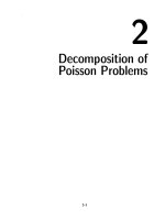
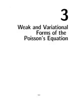
The geometry of a three-node triangular element is graphically defined in Figure
4.1.
By defining li to be length of side edge opposite to node i and hi as
height from node i to side i according to Figure 4.1 one obtains
li =
2
x2jk + yjk
and
hi =
2A
,
li
(4.2.1)
where A is the triangle area, which may be calculated as
2A = x21 y31 − x31 y21 = x31 y12 − x12 y32 = x13 y23 − x23 y13 .
4
(4.2.2)
3 (x3,y3)
3
l2
l1
h3
n2
n1
s2
s1
h2
y
1
h1
2
(x2,y2)
(x1,y1)
x
Figure 4.1.
s3
1
n3
2
l3
Geometric dimensions and unit vector definitions
for a triangular element.
The unit vector si along side i and the outward normal vector ni at
side i can then be defined as
nix −siy
xkj
six
1
si = siy =
and
ni = niy =
ykj
six . (4.2.3)
li
0
0
0
0
4.3
The triangular membrane element.
The construction of an ANDES triangular membrane element is described by
Felippa and Militello in [00]. The present description is adapted to the notation
used for the four-node quadrilateral element in Chapter 5.
The nodal degrees of freedom vi for the membrane element consists of
the in-plane translations u, v and the “drilling” degree of freedom θz :
ui
v
.
(4.3.1)
vi =
i
θz i
5
4.3.1 Basic stiffness.
The lumping of the constant membrane stresses to a node j is only a function
of the neighboring side edges ij and jk. The total lumping matrix can thus be
divided into the contributions to the separate nodes as
L1
L = L2 ,
(4.3.2)
L3
where
0
−xki
α
2
2
6 (xij − xkj )
yki
1
0
Lj =
2 α 2
2
6 (yij − ykj )
−xki
,
yki
α
3 (xkj ykj − xij yij )
(4.3.3)
and the nodal indices (i, j, k) take cyclic permutations of (1, 2, 3). The basic
stiffness is then computed as
Kb =
t
LCLT ,
A
(4.3.4)
where t is the element thickness and A the element area.
4.3.2 Higher order stiffness.
Felippa and Millitello [00] extracted the higher order behavior of the element
by defining the higher order degrees of freedom θ˜i as the nodal drilling degrees
of freedom minus the rigid body and constant strain rotation θ0 of the CST
element
θ˜i = θi − θ0 ,
(4.3.5)
where
θ0 =
1
[ −x32
4A
−y32
0
−x13
−y13
0
−x21
−y21
0]v .
(4.3.6)
By further splitting the hierarchical rotations into mean θ¯ = (θ˜1 + θ˜2 + θ˜3 )/3
and deviatoric components θi = θ˜i − θ¯ one gets
vx1
vy1
θ
1
2
1
1
0
0
θ
0
0
−
0
0
−
1
3
3
3
v
x2
1
2
1
θ2
0 −3
0
0
0
0
−
0
3
3
=
v
, (4.3.7)
y2
2
0
0 − 13
0
0 − 13
0
0
3
θ3
θ2
y32
y13
y21
x13
x21
x32
1
1
1
θ¯
4A
4A
3
4A
4A
3
4A
4A
3
v
x3
v
y3
θ3
6
which in matrix form reads
θh = Hθv v .
(4.3.8)
The pure-bending field.
The pure bending field is connected to the deviatoric hierarchical rotations θi as
b1
b1
b21|1
b21|2
ρ1 χ21|1
=
ρ
=
5 χ32|1
b32|1
−ρ1 χ13|1
b13|1
−ρ2 χ21|1
ρ3 χ32|1
ρ4 χ13|1
ρ4 χ21|1 θ1
−ρ3 χ32|1 θ2 = Qb1 θ
ρ2 χ13|1
θ3
ρ4 χ21|2 θ1
ρ2 χ21|2 −ρ1 χ21|2
ρ1 χ32|2 −ρ2 χ32|2 θ2 = Qb2 θ
= ρ4 χ32|2
b2 =
b32|2
−ρ3 χ13|2
ρ5 χ13|2
ρ3 χ13|2
θ3
b13|2
ρ5 χ21|3 θ1
ρ3 χ21|3 −ρ3 χ21|3
b21|3
=
ρ2 χ32|3 −ρ1 χ32|3 θ2 = Qb3 θ (4.3.9)
= ρ4 χ32|3
b32|3
−ρ2 χ13|3
ρ4 χ13|3
ρ1 χ13|3
θ3
b13|3
where
χij|k =
4A
2
3lij
and χij|i = χij|j = −
2A
2
3lij
(4.3.10)
and the ρi are numerical coefficients to be chosen. Coefficients ρi that optimize
in-plane bending behavior of rectangular mesh units are found to be [00]
ρ2 = 1 ,
ρ3 =
1
2
and ρ1 = ρ4 = ρ5 = 0 .
(4.3.11)
Having defined the matrices Qbi in (4.3.9), the bending strains over the
element can now be interpolated linearly between the nodes:
b
= (ζ1 Qb1 + ζ2 Qb2 + ζ2 Qb2 )θ = Bb θ .
(4.3.12)
The torsional field.
The torsional field is connected to the mean deviatoric rotation θ¯ and is given
in [00] as
t21
χ21|1 ζ21
¯.
= 3 χ32|2 ζ21 θ¯ = Bt θ
t =
t32
χ13|3 ζ21
t13
7
The total strain field.
The total natural coordinate strain field is the combination of the purebending and torsional strain fields expressed with respect to the visible degrees
of freedom
= b+ t
= Bb θ + Bt θ¯
(4.3.13)
= [ Bb
Bt ] θh
= [ Bb
Bt ] Hθv v
= Bv .
The stiffness matrix.
The higher order stiffness matrix is computed as
BT C B dA
Kh =
where
C = TT CT ,
(4.3.14)
A
and
T−1
s12 2x
= s23 2x
s31 2x
s12 2y
s23 2y
s31 2y
s12 x s12 y
s23 x s23 y .
s31 x s31 y
(4.3.15)
Matrix T transforms the natural coordinate strains to Cartesian strains, while
T−1 does the opposite.
4.4
The triangular bending elements.
The bending component of the triangular shell element is based on the linear
three node plate bending element AQR developed by Militello [00]. A higher
order stiffness is also developed by sanitizing the BCIZ element [00]. Two basic
stiffnesses exist, one based on linear interpolation of normal rotations along a
side edge and one based on quadratic variation of the normal rotation. The
triangular ANDES bending elements can thus be formed by combining several
basic and higher order stiffnesses.
The nodal bending degrees of freedom vi consists of the out of plane
translation w and the in-plane rotations θx and θy
wi
vi = θx i .
θx i
8
(4.4.1)
4.4.1 Basic stiffnesses.
Kb is one of the basic stiffness matrices described by Militello in [00] as
Kb =
where
1
Ll CLTl
A
Ll 1
Ll = Ll 2
Ll 3
or Kb =
1
Lq CLTq ,
A
Lq 1
and Lq = Lq 2 .
Lq 3
Lq i and Lq i are described in equation (0.0.0) and (0.0.0) respectively. The
nodal indices (i, j, k) in the equations above takes the cyclic permutations of
(1, 2, 3) as in the case of the membrane lumping.
4.4.2 BCIZ higher order stiffness.
The BCIZ element developed by Bazeley et al. [00] is an historically important
nonconforming element. However, the element is known not to pass the Patch
Test. In fact the puzzling behavior of the element motivated the original development of that test. The use of the BCIZ element as an higher order stiffness
for a triangular Free Formulation plate bending element was developed by Felippa, Haugen and Militello [00]. The transverse displacement field of the BCIZ
element was given explicitly by Felippa [00] as
T
ζ12 (3 − 2ζ1 ) + 2ζ1 ζ2 ζ3
−ζ12 (y12 ζ2 + y13 ζ3 ) − 12 (y12 + y13 )ζ1 ζ2 ζ3
1
2
ζ
(x
ζ
+
x
ζ
)
+
(x
+
x
)ζ
ζ
ζ
12
2
13
3
12
13
1
2
3
1
2
2
ζ2 (3 − 2ζ2 ) + 2ζ1 ζ2 ζ3
1
2
w = −ζ2 (y23 ζ3 + y21 ζ1 ) − 2 (y23 + y21 )ζ1 ζ2 ζ3
v
1
2
ζ2 (x23 ζ3 + x21 ζ1 ) + 2 (x23 + x21 )ζ1 ζ2 ζ3
ζ32 (3 − 2ζ3 ) + 2ζ1 ζ2 ζ3
1
2
−ζ
(y
ζ
+
y
ζ
)
−
(y
+
y
)ζ
ζ
ζ
31
1
32
2
31
32
1
2
3
2
23
1
ζ3 (x31 ζ1 + x32 ζ2 ) + 2 (x31 + x32 )ζ1 ζ2 ζ3
The strain displacement matrix Bχ giving the natural curvatures from the visible
degrees of freedom is obtained by double differentiation of the displacement field
with respect to the triangular coordinates and appropriate relations detailed in
the Appendix of [00]:
χ12
χ = χ23 = Bχ v = (Bχ0 + Bχ1 ζ1 + Bχ2 ζ2 + Bχ3 ζ3 )v ,
χ31
9
where
BTχ0
6
0
0
6
= 0
0
0
0
0
0
0
0
6
0
0
6
0
0
6
0
0
0
0,
0
6
0
0
BTχ1
−12
4y12
−4x12
0
= −2y21
2x21
0
0
0
BTχ2
and
0
−2y12
2x12
−12
= 4y21
−4x21
0
0
0
0
0
0
−12
4y23
−4x23
0
−2y32
2x32
BTχ3
−4
y12 − y13
−x12 + x13
−4
= y21 − y23
−x21 + x23
−4
y31 + y32
−x31 − x32
−4
y12 + y13
−x12 − x13
−4
−y21 + y23
x21 − x23
−4
−y31 + y32
x31 − x32
−12
4y13
−4x13
0
0 ,
0
0
−2y31
2x31
−4
−y12 + y13
x12 − x13
−4
y21 + y23 ,
−x21 − x23
−4
y31 − y32
−x31 + x32
0
0
0
0
−2y23
2x23
−12
4y32
−4x32
0
−2y13
2x13
0
0 .
0
−12
4y31
−4x31
By using a natural curvature constitutive matrix Cχ = TT CT the
higher order stiffness matrix becomes
BTχd Cχ Bχd dA,
Kh =
A
¯ χ and B
¯ χ = Bχ0 + 1 (Bχ1 + Bχ2 + Bχ3 ).
where Bχd = Bχ − B
3
10
4.4.3 ANDES higher order stiffness by direct curvature readings.
The three node ANDES element is based on direct curvature interpolation of the
natural curvatures. As reference lines Millitello [00] chose the three side edges,
which function as Hermitian beams. The nodal strain gage readings expressed
as function of the visible degrees of freedom can be written
g = Qv = QF ∗Fv ,
(4.4.2)
where
gT = [ κ31|1
vT = [ vz 1
κ12|1
θx 1
κ12|2
θy 1
κ23|2
vz 2
θx 2
κ23|3
θy 2
κ31|3 ] ,
vz 3
θx 3
(4.4.3)
θy 3 ] ,
−6
4
4
0
0
0
6
2
2
6 −2 −2
0
0
0
−6 −4 −4
2
2 −6
4
4
0
0
0
6
QF =
0
0 −6 −4 −4
6 −2 −2
0
0
0
0
6
2
2 −6
4
4
6 −2 −2
0
0
0 −6 −4 −4
(4.4.4)
and
F31
F12
F
F = 12
F23
F23
F31
F31
F12
F12
F23
F23
F31
F31
F12
F12
F23
F23
F31
F12 =
where
F23 =
F31 =
1
2
l12
1
2
l23
1
2
l31
n12 x
l12
n23 x
l23
n31 x
l31
n12 y
l12
n23 y
l23
n31 y
l31
.
(4.4.5)
The six curvature gage readings in g give two curvature gage readings
at each node. But three natural coordinate curvature readings are necessary to
transform to the Cartesian strains at each node. A third reading is obtained by
invoking the following projection rule [00]: the natural curvature κij is assumed
to vary linearly along side ij and constant along lines normal to side ij. Node
k is then assigned a κij value according to the projection of the node on line ij.
This assumption can be expressed as the matrix relationship
κ = Aκ g ,
11
(4.4.6)
where
Aκ =
0
0
ζ1 + λ13 ζ2
ζ1 + λ12 ζ3
0
0
ζ1 + λ21 ζ3
0
0
and
λij =
0
ζ2 + λ23 ζ1
0
0
ζ2 + λ32 ζ1
0
(4.4.7)
0
0
ζ3 + λ31 ζ2
−sTki sij lki
.
lij
The deviatoric parts of the strains are now obtained by subtracting the
mean strain:
Aκ dA ,
Aκd = Aκ −
A
which gives
0
0
ζ˜1 + λ13 ζ˜2
Aκd =
ζ˜1 + λ12 ζ˜3
0
0
ζ˜1 + λ21 ζ˜3
0
0
0
˜
ζ2 + λ23 ζ˜1
0
0
˜
ζ2 + λ32 ζ˜1
0
(4.4.8)
0
0
ζ˜3 + λ31 ζ˜2
in which ζ˜i = ζi − 13 .
The deviatoric cartesian curvatures.
The deviatoric cartesian strain distribution over the element can now be expressed as
κd = Tκ = TAκd g = TAκd Qv = Bd v ,
where T is defined in equation (4.3.15).
The higher order stiffness.
Finally, the higher order stiffness can be computed from the deviatoric strains
as
Kh =
BTd CBd dA .
(4.4.9)
A
12
4.5
Nonlinear extensions for a triangular shell element.
The linear triangular shell element is now ready to be incorporated in the corotational formulation discussed in Chapter 2. The shadow element C0n is best
fit to the deformed element Cn by a rigid body motion of the undeformed initial
element C0 . However this “best fit” is not unique. The rotation gradient matrix
G defined in equation (0.0.0) can be split into contributions from each node
as
˜
G θx
˜θ ,
˜
˜
˜
˜
˜
˜ r = G δ˜
δω
v where G = [ G1 G2 G3 ] = G
(4.5.1)
y
˜θ
G
z
and δ˜
v is defined as
v1
δ˜
δ˜
v = δ˜
v2
δ˜
v3
where
δ˜
vi =
˜i
δu
˜i
δω
.
(4.5.2)
Three techniques for fitting the shadow element are discussed below. Each
˜ i submatrices.
technique produces different G
4.5.1 Aligning a triangle side.
This procedure is similar to Rankin’s alignment of the C0n and Cn elements [00]
in that it uses a common side edge direction for those configurations. Whereas
Rankin picks side 13 for the unit-vector e2 and node 1 as the origin of the
coordinate system, the current approach aligns the directions of side 12 with
the e1 axis and uses the element nodal average (triangle centroid) as the origin
of the coordinate system. This choice of centroid as origin is necessary in order
to satisfy the orthogonality of PT and P in equation (0.0.0) .
Through consistent variation of the foregoing choice of local coordinate
˜ i of equation (4.5.1) is obtained as
system, the nodal submatrices G
0
0
x32 0 0 0
˜1 = 1 0
G
0
y32 0 0 0 ,
2A
2A
0 0 0 0
0 − l12
0
0
x13 0 0 0
˜2 = 1 0
(4.5.3)
0
y13 0 0 0 ,
G
2A
2A
0
0
0
0
0
l12
0 0 x32 0 0 0
˜ 3 = 1 0 0 y32 0 0 0 ,
G
2A
0 0 0 0 0 0
where A is the area of the triangle and l12 is length of side 12. (This variation
is carried out in more detail for the four node shell element i Section 0.0.)
13
3
3
α1
(α1+β)
(α2+β)
α2
α3
1
Figure 4.2.
2
1
(α3+β)
2
Definition of side edge angular errors.
∂w
The in-plane rotations can be recognized as ωx = ∂w
∂y and ωy = − ∂x , using
the geometric shape functions to interpolate w. This choice of shadow element
˜ = XA
˜
fit satisfies the required splitting of the rotation gradient matrix as G
where only matrix X is coordinate dependent as required for the consistency
condition in equation (0.0.0). On the other hand, this choice does not give
an invariant deformational displacement vector for the element in the sense
discussed in Section 0.0.0.
4.5.2 Least square fit of side edge angular errors.
Nyg˚
ard [00] and Bjærum [00] place the C0n element in the plane of the deformed element Cn with node 1 coinciding. The present study utilizes coinciding
centroids. The in-plane orientation of the shadow element is then determined
by a least square fit of the side edge angular errors. According to Figure 4.2 the
squared-error sum is
e2 = α12 + α22 + α32 .
(4.5.4)
By rotating the shadow element an angle β the square of the errors becomes
e2 (β) = (α1 + β)2 + (α2 + β)2 + (α3 + β)2 .
(4.5.5)
Minimizing with respect to β:
∂e2 (β)
=0
∂β
⇒
1
β = − (α1 + α2 + α3) .
3
(4.5.6)
Consequently, the optimal in-plane position of the shadow element according
to this algorithm is given by the mean of the side edge angular errors. This
condition yields for the nodal submatrices
14
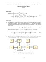
a)
c)
b)
θd
θd
β
θd
β
θd
Figure 4.3.
θd
θd
Patch of triangle elements subjected to pure stretching.
0
0
˜i = 1
G
2A 2A (− sjy +
3
lj
sky
lk )
0
0
2A
3 (
sjx
lj
−
skx
lk )
xkj
ykj
0
0 0 0
0 0 0.
0 0 0
(4.5.7)
The major advantage of this method is that it gives a unique fit independent of node numbering, which leads to a invariant deformational displacement
vector as discussed in section 0.0.0. The rotational gradient matrix cannot be
split into a coordinate dependent and independent part in order to be consistent
with equation (0.0.0). However, again, this is of minor importance for triangular
elements since the shadow element C0n and the deformed element Cn will be
close together for small membrane strains.
A more serious disadvantage of this fitting method is that it reintroduces
the problem of fictitious normal rotations when an element is subjected to pure
stretch.
This difficulty is illustrated in Figure 4.3, where the C0n elements rotate
due to the in-plane rotation of the diagonal. The deformational displacement
vector is then computed as the difference between Cn and C0n . A deformational
normal rotation is thus picked up since the predictor step gives no rotation at
the nodes and the deformational rotation is the total rotation minus the rigid
body rotation
θd = (θ − β) = −β .
(4.5.8)
This problem is similar to that pointed out by Irons and Ahmad [00] when
defining drilling degrees of freedom as the mean of the side edge rotations at an
15
node. This was overcome by Bergan and Felippa [00] when they defined the
∂v
normal rotation as θz = 12 ( ∂x
− ∂u
∂y ) for the linear FF membrane element. It
is seen that the problem of fictitious normal rotations has been thus been reintroduced for the nonlinear case by the choice of shadow element positioning.
This problem is even more pronounced with the side edge alignment procedure
described in Section 4.5.1.
4.5.3 Fit according to CST-rotation.
As with the least square fit of side edge angular errors the shadow C0n element is
chosen to be co-planar with the deformed element Cn , and the centroids coincide.
By using the normal rotation of the CST element as the rigid body
rotation β for the in-plane positioning of the shadow element, one avoids the
problem of fictitious normal rotations when an element is subjected to pure
stretching.
∂v
The definition θz = 12 ( ∂x
− ∂u
∂y ) gives an invariant definition of the normal
rotation for the infinitesimal case. This also provides the variation of the rigid
body rotation with respect to the visible degrees of freedom.
Extending the above definition to finite rotations seems to suggest
θz =
1
∆v
∆u
(tan−1 (
) − tan−1 (
)) .
2
∆x
∆y
(4.5.9)
However this choice gives slightly varying results with respect to the orientation of the (x, y)-coordinate system. In order to obtain a completely invariant
positioning with respect to node numbering, the rigid body rotation can been
computed as the average of the rotations obtained with the local x-axis along
each of the three side edges. The continuum mechanics definition of the normal
∂v
∂v
rotation is θ˜z = 12 ( ∂x
− ∂x
). This definition is invariant with respect to the orientation of the x and y coordinate axis, and gives the rotation gradient matrix
as
0
0
xkj 0 0 0
˜i = 1 0
G
(4.5.10)
0
ykj 0 0 0
2A
1
1
0 0 0 0
− 2 xkj − 2 ykj
In the present investigation the three techniques just outlined for choosing the shadow element position were tested in the nonlinear problems reported
in Chapters 7 and 8.
16