Ứng xử kháng chọc thủng của liên kết cột ống thép nhồi bê tông và sàn phẳng bê tông cốt thép tt tiếng anh
Bạn đang xem bản rút gọn của tài liệu. Xem và tải ngay bản đầy đủ của tài liệu tại đây (1.54 MB, 27 trang )
MINISTRY OF EDUCATION AND TRAINING
THE UNIVERSITY OF DANANG
DINH THI NHU THAO
PUNCHING SHEAR BEHAVIOR OF
FLAT SLAB - CONCRETE FILLED TUBULAR
(CFT) COLUMN CONNECTIONS
MAJOR: MECHANICAL ENGINEERING
CODE: 62.52.01.01
DOCTORAL THESIS SUMMARY
Danang – 2019
The work was finished at DANANG UNIVERSITY
Science Advisor:
1. Assoc. Prof. Dr. NGO HUU CUONG
2. Assoc. Prof. Dr. TRUONG HOAI CHINH
Reviewer 1: ……………………………………………………..
…………………………………………………………………...
Reviewer 2: ……………………………………………………..
…………………………………………………………………...
Reviewer 3: ……………………………………………………..
…………………………………………………………………...
This dissertation is defended before The Assessment Committee at
The University of Danang
Time
Day
The dissertation is available at:
- National Library of Vietnam
- Information and Library Center of Danang University.
1
INTRODUCTION
1. The significance of this research
In the past decades, Steel-Concrete composite structures have been
used more and more widely in civil and industrial buildings in many
countries all over the world because of the outstanding advantages of the
combination between concrete and steel materials in both structural and
constructional aspect. The buildings using a combination of this structural
solution illustrated high strength, stiffness and toughness, which satisfies
the utility, economic efficiency, aesthetics as well as fire resistance
compared to traditional steel structure.
In high-rise buildings, the height of the floor, the size of column and
span of the structural components are important factors affecting the
economic efficiency and utility of the buildings. Therefore, the demand for
a new structure which can reduce the height of the floor, the size of the
column and increase the structural span, shorten the construction time and
save construction costs is a very necessary issue. The structural systems
using Concrete Filled Steel Tube (CFT) column and reinforced concrete
flat slab are relatively new structure in accordance with the above criteria,
and they are expected to be widely applied in the world in near future.
However, the effective connections between CFT column and flat slabs
and their punching shear behaviors, which are vital factors in ensuring the
strength of the structural system, have not yet been investigated adequately
and are attracting much attention from numerous researchers.
This thesis proposes a new type of the connection between the RC
flat slab and the CFT column with simplified details, easy fabrication and
suitable construction conditions in Vietnam. Through calculations and
preliminary simulations, the size and composition of the CFT column-flat
slab connections will be proposed. The shear resistant and punching shear
behavior of full-scale specimens will be investigated through empirical
experiment. In addition, the analytical model will be simulated by using
three-dimensional finite element software (ABAQUS) and the reliability
of the simulation technique will be verified by comparison with the
experimental results.
2. Objectives of the study
2
- The thesis proposed a unique connection between the reinforced
concrete flat slab and CFT columns with simplified details, easy
fabrication and suitable for Vietnam construction conditions.
- Investigate the punching shear behavior of RC flat slab-interior
CFT column connection by experiments and numerical analysis.
- Propose an analytical model to predict the punching shear capacity
of RC flat slab-interior CFT column connection.
3. Scientific and empirical significance of research
Scientific significance
In Vietnam, the application of CFT columns in buildings is
relatively new and not yet popular. The results obtained from the
experiments and simulations in this study will contribute to the new
arguments and knowledge as well as useful data for future research in this
field.
Empirical significance
Presently, the connections between the reinforced concrete flat slabs
and the CFT columns have been proposed and investigated by numerous
authors to investigate the structural behavior and efficiency for practical
application. The proposal of a new the connection between the reinforced
concrete flat slabs and the CFT columns, which contains a simplified detail
and is efficient as well as suitable for the construction conditions in
Vietnam, will be the prerequisite for further research on other types of
connections to develop structural solution for CFT column - reinforced
concrete flat slab in construction. In particular, the introduction of a
numerical model to predict the load-carrying-capacity of the connection in
accordance with the experimental results is essential to obtain reliable
results in the structural design of this type of connections in practice
without any costly and time-consuming experiments.
4. Content of Research
- Provide an overview of the research project.
- Propose a unique connection between the reinforced concrete flat
slabs and the CFT column.
- Full scale test specimen fabrication.
3
- Test setup and Experimental program.
- Process, analyze data and evaluate the results.
- Simulate the behavior of the connections by using ABAQUS
three-dimensional finite element software with considering the nonlinear
geometrical effects and nonlinear material effects.
- Verify the reliability of the simulation technique by comparing
the test results with the experimental results.
- Draw the conclusions and recommendations.
5. Research Methodology
Use experimental research methods in combination with numerical
simulation by using ABAQUS three-dimensional finite element software
6. Object and scope of the study
Research subjects:
Experimental investigation and simulation of the behavior of CFT columnreinforced concrete flat slab connections subjected to punching shear load.
Research scope:
- Conventional Flat slab system, no pre-stress effect, no-hole near
the connection, interior CFT column
- Not consider the combination action of moment cause by
horizontal loading and the column axis;
- Only use increased static load, not cyclic or dynamic load.
7. The composition of the thesis
The thesis contains 126 A4 pages with following composition:
Introduction.
Chapter 1: Overview of CFT column-reinforced concrete flat slab
connections.
Chapter 2: Experimental Program of CFT column-flat slab connections
Chapter 3: Investigation the Behavior of CFT Colum-RC Flat Slab
Connections by Numerical Method.
Conclusion and development direction.
8. Contribution of the thesis
- The thesis proposed a unique connection between reinforced
concrete flat slab and CFT columns with simplified details, easy
fabrication and suitable for domestic construction conditions.
4
- Establish experimental procedures and conduct experiments to
investigate the punching shear behavior of the proposed RC flat slab-CFT
column connection.
- Simulate the behavior of the connection by using ABAQUS
three-dimensional finite element software and verify with the experimental
results.
- Establish a calculation process to predict the punching shear
capacity of proposed RC flat slab-interior CFT column connection based
on Vietnam Standard TCVN 5574: 2012, Euro Code 2 and American
standard ACI 318-11.
CHAPTER 1: OVERVIEW OF CFT COLUMNREINFORCED CONCRETE FLAT SLAB CONNECTIONS
1.1 Concrete Filled Tubular (CFT) Columns
1.2 Reinforced Concrete Flat Slabs
1.3 The Connections between Reinforced Concrete Flat Slabs and CFT
Columns
1.3.1 The Study of Satoh and Shimazaki (2004)
Satoh and Shimazaki (2004) [37] experimentally investigated the
punching shear behavior of square CFT column- RC flat slab joints
Diaphragm
Connection Plate
Figure 1.22 and Figure 1.23: The Connection Details and
Experimental Setups of Satoh and Shimazaki
1.3.2 The Study of Su and Tian (2010)
Su and Tian (2010) [40] investigated the punching shear behavior of
interior circular CFT column – RC Flat slab connection subjected to
earthquake load. The test results showed this type of connection can sustain
5
a larger value of drift ratio than the conventional column-reinforced
concrete flat slab connections.
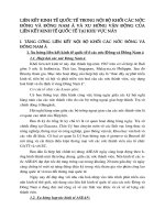
1.3.3 The Study of Yan (2011)
Yan (2011) [44] has proposed two types of CFT column- flat slab
connections. The interior CFT column contains I-type shear reinforcement
detail (type 1) and box type shear reinforcement detail (type 2). Two
specimens were tested under punching shear until failure. The
experimental results show that the ultimate load carrying capacity of the
type-1 specimen was 417 kN while the type-2 one was 569 kN
Hình 1.32: The type-1 specimen of
Yan
Hình 1.34: The type-2 specimen of
Yan
1.3.4 The Study of Kim et. al (2014)
Kim et al. (2014) [23] proposed a rigid shear resistance details for
CFT column-RC flat slab connections by using steel shearheads. The test
results showed that the punching shear capacity of the connections using
steel shearheads was higher than that of conventional details.
1.3.5 Local researchers
1.4 Pros and Cons of existing CFT column-flat slab connections
1.4.1 Pros: Ensure the require strength and ductility
1.4.2 Cons: The connections proposed by Satoh and Shimazak, Yan, and
Kim et al. have complicated details and were embedded in slab causing a
difficulty construction and installation of steel reinforcement. Moreover,
the forces were transmited from the Slabs to the CFT columns only through
steel tubular shell by shear reinforcement details, not through the concrete
core.
1.5 Punching shear capacity of RC Column-Flat Slab Connection in
existing Building Design Code
6
1.5.1 Vietnam Building Code 5574:2012
1.5.2 EC-2 Building Code
1.5.3 ACI 318-11 Building Code
1.6 Conclusions
Chapter 1 presented the advantages of the CFT columns, the
reinforced concrete flat slabs as well as the CFT column-RC flat slabs
connection and the overview of this type of components . Through that, the
thesis also suggested the necessity of proposing a new connection between
reinforced concrete flat slabs and the CFT column and following by the
empirical research and simulating research to clarify the behavior and the
effectiveness of the proposed connection.
CHAPTER 2. EXPERIMENTAL PROGRAM OF CFT
COLUMN-FLAT SLAB CONNECTIONS
2.1 Experimental specimens
2.1.1 Introduction
The proposed connection is denoted as S-02-M-V and the
conventional RC column-flat slab connection with the same column
diameter and slab thickness is denoted as S-C-V.
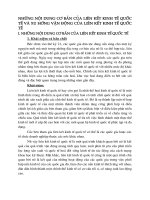
2.1.2 Characteristic and details of proposed connections
2.1.2.2 The details of proposed connection
The details of proposed connection include (Figure 2.1 and Figure 2.2):
20
80
8
8
100
180
180
25
20 20 20 20
155
20
25
155 16
155
20202020
20
Steel column with
D=400mm
Steel plate with
the thickness of
16mm
120
120
8
Stiffener detail
80 100
180
125
400
400
125
650
Figure 2.1 and Figure 2.2: The details of connection
2.1.2.2 Pros and Cons of proposed CFT column-flat slab connections
✓ Pros
7
− Steel reinforcement has a continuous detail.
− The stiffener and the supporter system transfer the vertical loads from
50
50
flat slab system to both steel tubular shell and concrete core and
increase the integrity of the connections.
− Moreover, because the stiffener and the supporter system are located
beneath the slab, the installation of longitudinal reinforcement is as
convenient as conventional RC flat-slab system.
✓ Cons
Because the stiffener and the supporter system are located beneath
the slab, aesthetics is not guaranteed.
2.1.3 Geometric characteristics and details of specimens
2.1.3.1 S-C-V specimen
900
d14a240
1050
400
2500
1050
50
50
21-d14a120 = 2400
2500
50
d14a120
200 200
A
A
11-d14a240 = 2400
2500
A
A
21-d14a120 = 2400
2500
8d16
d6a150
50
11-d14a240 = 2400
2500
50
Figure 2.3: The layout
of upper longitudinal
reinforcement of S-C-V
50
Figure 2.4: The layout
of lower longitudinal
reinforcement of S-C-V
Figure 2.5: A-A Section of S-C-V
A
50
50
155
120
200 200
A
11-d14a240 = 2400
2500
A
120
180
180
8
A
21-d14a120 = 2400
2500
2380
50
50
2.1.3.2 S-02-M-V specimen
50
21-d14a120 = 2400
2500
50
Figure 2.6: The layout of
upper longitudinal
reinforcement of -02-M-V
50
11-d14a240 = 2400
2500
80100
180
50
Figure 2.7: The layout of
lower longitudinal
reinforcement of -02-M-V
20
50
400
440
20
21-d14a120 = 2400
2500
Figure 2.8: A-A Section
of -02-M-V
2.1.4 Experimental setup
– The experimental process is divided into 2 stages as follows:
50
8
Connection
subjected to
predisplacement
Cyclic load
Gap
Figure 2.10: Stage 1- The connection
is subjected to increasing cyclic load
up to drift ratio of H/140
Figure 2.11: Stage 2- The connection is
subjected to vertical load until failure
due to punching shear
2.2 Experimental apparatus
2.2.1 Loading frame
2.2.2 LVDT system, straingauge and measuring devices
2.3 Experimental process and test result analysis
2.3.1 Material
2.3.1.1 Concrete
a) Comperessive strength of
specimens, fcm
b) Splitting tensile strength of specimens, fsp
Figure 2.13: Comperessive Splitting tensile strength tests
The average compressive strength of specimes, fcm, was 40.4 MPa
and the average splitting tensile strength of specimens fctm = 0.9fsp = 3.16
MPa. The test results were illustrated in Table 2.4 và Table 2.5.
2.3.1.2 Steel plate
Steel plates and steel cover of the CFT of S-02-M-V specimen used
Q345B steel. Tensile tests showed that the plate has the yield strengh of
351 MPa, and the ultimate strength of 489 MPa.
9
500
Stress (MPa)
400
300
200
100
0
0
0.02 0.04 0.06 0.08 0.1 0.12 0.14
Strain
Figure 2.14: Stress-strain relationship of steel plate
Stress (N/mm2)
2.3.1.3 Longitudinal reinforcement
Longitudinal reinforcement used in this experiment is VietnameseJapanese steel with the diameter of 14mm- SD390. Tensile tests showed
that the longitudinal reinforcement has the yield strengh of 532.5 MPa, and
the ultimate strength of 614.0 MPa.
700
600
500
400
300
200
100
0
0
0.05
0.1 0.15
Strain
0.2
Figure 2.15: Stress-strain relationship of longitudinal reinforcement 14
2.3.2 Installation of LVDTs and strain gauges
2.3.2.1 The LVDTs installation of S-C-V and S-02-M-V:
The LVDTs were attached above the slab after the specimen has
been mounted into the loading system and denoted as D1, D2, D3, D4, D5,
D6 (Figure 2.16 and Figure 2.17).
100
1050
1050
475
50 200
200 50
100
100
D2A
D3A
200
D6
20
100
200
100
D4A
2500
D1 D3
D5
20
475
200
160
100
200
D4A
1050
D6
200
475
2500
H
D3A
D3
50
D1
D2
D4
100
100
D1A
100
200
100
475
50 200
D3A
200 50
475
100
D3
20
200
160
D2A
100
D1
D5
D1A
D2
D4
H
20
D2A
100
100
850
100
1050
200
1050
400
2500
D5
200
850
475
50
100
50
1050
200
2500
200
850
400
850
2500
Figure 2.16: The layout of LVDTs
of S-C-V and S-02-M-V
Figure 2.17: Elevation of LVDTs
of S-C-V and S-02-M-V
200
10
2.3.2.2 The strain gauge installation of S-C-V and S-02-M-V
The steel strain gauges were denoted as S1, S2, S3, S4, S5, S6 (Figure 2.18
and Figure 2.20). The concrete strain gauges were denoted as C1, C2, C3,
C3, C5 (Figure 2.5 và Figure 2.6).
S6
C3
Figure 2.19: Strain gauge installation of
concete (S-C-V specimen)
d = 184
Figure 2.18: Strain gauge installation of
the upper layer of longitudinal
reinforcement (S-C-V specimen)
C4
d = 184
S3
d = 184
C1
S1
S2
45°
S3
S2
S1
d = 184 S4
d = 184
C2
S4
C1
C5
d = 184
A
C2
B
400
S5
Figure2.20: The concrete strain gauge and upper layer steel strain gauge
S-02-M-V
2.3.3 Experimental process
2.3.3.1 Specimen casting
Figure 2.21.
Formwork and
reinforcement
installation of S-C-V
Figure 2.22:
Concrete pouring
of S-C-V
Figure 2.23:
Formwork and
reinforcement
installation of
S-02-M-V
Figure 2.24:
Concrete pouring
of S-02-M-V
2.3.3.2 Transpostation, assembly and installation of specimen
11
Hình 2.25: Installation of S-C-V
Hình 2.26: Installation of S-02-M-V
2.3.3.3 Load cell installation
Figure 2.27: Load cell erection for S-C-V and S-02-M-V
2.3.3.4 Measurement device installation
Figure 2.28: LVDT
installation for S-C-V
Figure 2.29: LVDT
installation for S-02-M-V
Figure 2.30: Steel and Concrete strain gauge installation for S-C-V and S-02M-V
12
Figure 2.31: The connections between the straingauges and the data logger
900
800
700
600
500
400
300
200
100
0
Thực nghiệm-D1
Thực nghiệm-D2
Thực nghiệm-D3
Thực nghiệm-D4
0
4
900
800
700
600
500
400
300
200
100
0
Force (kN)
Force (kN)
2.3.4 Experimental process and test results of S-C-V
2.3.4.1 Experimental process
The initial load was about 5% of the total calculated failed force,
about 30 kN / load segment.
2.3.4.2 Test results of S-C-V
Punching shear force: 827.3 kN
8 12 16 20 24
Displacement(mm)
Thực nghiệm-S1
Thực nghiệm-S2
0
Figure 2.32: Force-Displacement
curve of S-C-V
0.01
0.02
Strain
0.03
0.04
Hình 2.33: Force-strain curve of
longitudinal reinforcement of S-C-V
Lực (kN)
2.3.4.3 Punching cone characteristics of S-C-V
The test esults showed that the slab was damaged totally due to the
punching shear force. The value of punching shear force was recorded at
827.3 kN (Figure 2.36).
-0.0015
Thực nghiệm
Thực nghiệm
Thực nghiệm
Thực nghiệm
C1
C2
C3
C4
900
800
700
600
500
400
300
200
100
0
-0.001
-0.0005
Biến dạng
Hình 2.35: Force-strain curve for
concrete of S-C-V
0
Hình 2.36: The shape of punching
cone of S-C-V
13
Force (kN)
2.3.5 Experimental process and test results of S-02-M-V
2.3.5.1 Stage 1
The horizontal force was loaded by using a hydraulic actuator with a
displacement-controlled method. The maximum load with respect to
17mm displacement was 74 kN.
80
70
60
50
40
30
20
10
0
0
4
8
12 16 20
Horizontal displacement (mm)
Figure 2.38: Force-Horizontal displacement at column head
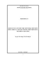
2.3.5.2 Stage 2
The CFT column-RC flat slab was subjected to vertical load until failure
and the ultimate punching shear load reached 1024.00 kN.
Chuyển
Chuyển
Chuyển
Chuyển
Chuyển
Chuyển
0
3
6
1100
1000
900
800
700
600
500
400
300
200
100
0
Force (kN)
Force (kN)
1100
1000
900
800
700
600
500
400
300
200
100
0
vị D1
vị D2
vị D3
vị D4
vị D5
vị D6
9 12 15 18 21 24 27
Displacement (mm)
Force (kN)
Figure 2.39: Force-displacement
relationship of S-02-M-V
Biến dạng C1
Biến dạng C2
Biến dạng C3
Biến dạng C4
-0.003
-0.002
-0.001
Biến dạng S1
Biến dạng S2
Biến dạng S3
Biến dạng S4
Biến dạng S5
Biến dạng S6
0
0.005
0.01
0.015
Figure 2.40: Force-strain relationship of
steel re-bar of S-02-M-V
1100
1000
900
800
700
600
500
400
300
200
100
0
0
0.02
Strain
0.001
Strain
Figure 2.41: Force-strain curve for
concrete of S-02-M-V
Figure 2.42: The shape of
punching cone of S-02-M-V
14
2.3.5.4 Punching cone characteristics of S-02-M-V
Stage 1: Horizontal displacement at column head reached 17 mm
with respect to a Force of 74 kN, there is no cracks appeared on the surface
of slab.
Stage 2: The test results showed that the structural system was
destructive by punching shear. The ultimate punching shear load reached
1024.00 kN (Figure 2.42).
2.4 Conclusions
Chapter 2 presents the proposed flat concrete joint - reinforced concrete
and reinforced concrete reinforced concrete floor - CFT column,
experimental results of concrete materials, flat steel and reinforced
concrete floor and real process. Determine the punctured behavior of the
sample SCV and sample S-02-MV. The results of the experiments are
shown in diagrams of the relationship between puncture force and
quantities such as displacement, stress, strain in concrete and
reinforcement of samples S-C-V and S-02-M-V. The shape of the puncture
tower and the force-bearing behavior are similar to those of other authors
in the world.
CHAPTER 3 INVESTIGATE THE BEHAVIOR OF CFT COLUMRC FLAT SLAB CONNECTIONS BY NUMERICAL METHOD
3.1 Introduction
3.2 Overview of ABAQUS Software
3.2.1 Components in ABAQUS
3.2.2 Types of components used in simulation
3.2.3 Concrete material model
3.2.3.1 Concrete material modeling in Compression
3.2.3.2 Concrete material modeling in Tension
3.2.3.3 Modeling of plastic behavior of Concrete material
3.2.3.4 Concept of yield surface in plastic model
3.2.4 Contact interaction between surfaces of the components
3.2.4.1 “Tie” interaction
3.2.4.2 “Embedded elements” interaction
3.2.4.3 “Coupling” interaction
15
3.2.4.4 “Hard contact” interaction
3.3 Numerical simulation method in this Study
3.3.1 Material modeling
4
Stress (MPa)
Stress (MPa)
50
40
30
20
10
3
2
1
0
0
0
0.001 0.002 0.003 0.004
Strain
Figure 3.16: Compressive stressstrain curve
0
0.1
0.2
0.3
Crack width (mm)
0.4
Figure 3.17: Tensile stress-crack width
curve
The typical tensile stress-strain curve of steel plates and steel rebars
(d=14mm) of S-C-V and S-02-M-V were illustrated in Figure 2.14 and
Figure 2.15
3.3.2 Punching shear behavior simulation of RC interior Flat slabcolumn connection (S-C-V Specimen)
3.3.2.1 The components of S-C-V
Figure 3.18:
Geometrical
modeling
Figure 3.19:
Concrete
material
modeling
Figure 3.20:
Steel
reinforcement
modeling
Figure 3.21:
Upper and lower
support modeling
3.3.2.2 Contact interaction of S-C-V
Table 3.3: Contact interaction of S-C-V
Components
Form of
Interacted
interactions
components
RC Flat slab
Hard contact
− Upper and lower
boundary steelsupport plate
Steel rebars d=14mm Embedded element
− RC Flat slab
− RC Column
3.3.2.3 The boundary condition of S-C-V
16
The boundary conditions used in simulation is similar to those in
experiment, the 4 upper and lower boundaries are pinned connections
u1=u2=u3=0 (Figure 3.24 and 3.25)
Figure 3.24: Simulation
for the boundary
condition of upper
surface in S-C-V
Figure 3.25 Simulation
for the boundary
condition of lower
surface in S-C-V
Figure 3.26: Meshing
for S-C-V
900
800
700
600
500
400
300
200
100
0
Force (kN)
Force (kN)
3.3.2.4 Creating meshes for S-C-V specimen
The size of meshes for concrete element, steel plate support element and
steel rebars is 50mm. The result was presented in Figure 3.26.
3.3.2.5 The comparison between the numerical simulation results and
experimental results (specimen S-C-V)
Mô phỏng-D1
Thực nghiệm-D1
0
5
10
15
20
Displacement (mm)
Figure 3.27: Forcedisplacement D1 curve
for S-C-V
25
900
800
700
600
500
400
300
200
100
0
Mô phỏng-S1
Thực nghiệm-S1
0
0.01
0.02
Strain
0.03
0.04
Figure 3.29: Force-strain S1 curve
for S-C-V
3.3.2.6 The formation of cracks and punching cone in the simulation of SC-V
Along with the development of radial cracks, tangen cracks outside the
perimeter of the column are formed, then these tangent cracks are joined
together to form the punching cone at a rate of loading of 759.58 kN
(Figure 3.34).
17
b
Figure 3.32: The first
tangent cracks appear
in S-C-V
Figure 3.33: Cracks
appear in the direction
of the four corners of
the slab in S-C-V
a
Figure 3.34: Shape of
punching cone in S-C-V
3.3.2.7 Conclusion
The results show that the punching shear force of the simulation is
8.19% lower than that of the experiment and this value observed in the case
of D1 displacement is 6.82% lower. The cracking loading and area of
punching cone in the simulation are also close to the experimental results.
3.3.3 Punching shear behavior simulation of interior RC Flat slab-CFT
column connection (S-02-M-V Specimen)
3.3.3.1 The components of S-02-M-V
Figure 3.35:
Concrete material
modeling
Figure 3.36: Slab
Figure 3.37: Steel rebar modeling
and column
modeling
Figure 3.38: The modeling of stiffener, steel plate at column head and steel
column in S-02-M-V
18
3.3.3.2 Contact interaction of S-02-M-V
Table 3.5: Contact interaction of S-02-M-V
Components
RC Flat slab
Form of interactions
Hard contact
Concrete core in CFT
column
Steel column
Hard contact
Steel column
Tie
Stiffener
Stiffener
Hard contact
Tie
Steel plate-support
Steel rebar in slab
d=14mm
Hard contact
Embedded element
Hard contact
Interacted components
− Steel column
− Steel-plate support
− Steel column
− Stiffener
− Concrete core
− Flat slab
− Steel-plate support
− Stiffener
− Concrete core
− Steel column
− Steel-plate support
− Flat slab
− Flat slab
− Concrete core
3.3.3.3 The boundary condition of S-02-M-V
The boundary conditions used in simulation is similar to those in
experiment, the 4 upper and lower boundaries are pinned connections
u1=u2=u3=0 (Figure 3.43 and 3.44).
3.3.3.4 Creating meshes for S-02-M-V specimen
The size of meshes for concrete element, steel plate support element and
steel rebars is 50mm. The result was presented in Figure 3.45.
Figure 3.43: Simulation for the
boundary condition of upper surface
in S-02-M-V
Figure 3.45: Meshing for S-02-M-V
3.3.3.5 The comparison between the numerical simulation results and
experimental results (specimen S-02-M-V)
19
Stage 1:
Force (kN)
The connection is subjected to increasing cyclic load up to drift ratio of H/140.
90
80
70
60
50
40
30
20
10
0
Thực nghiệm
Mô phỏng
0
2
4
6
8 10 12 14 16 18
Displacement at the top of
column(mm)
Figure 3.46: Deformed shape of
S-02-M-V with respect to 17
mm displacement at the column
head
Figure 3.47: Force-displacement at column
head in S-02-M-V
Figure 3.48: Mises stress in slab with respect to 17 mm displacement at the
column head
Conclusion: During the simulation, the horizontal load does not cause
cracks in the Slab (Figure 3.48).
Stage 2
Applying the vertical load using displacement-controlled method until
completely failure.
Table 3.6: The comparison between the numerical simulation results and
experimental results (S-02-M-V)
Punching Displacement Displacement
shear
D1
D3
force
(mm)
(mm)
(kN)
S-02-M-V (experiment)
1024.00
23.43
17.56
S-02-M-V (simulation)
925.15
22.38
15.25
Coefficient of variation
9.65%
4.48%
13.15%
Force (kN)
1100
1000
900
800
700
600
500
400
300
200
100
0
Mô phỏng-D1
Force (kN)
20
Thực nghiệm-C1
Thực nghiệm-D1
0
3
6
9
12 15 18 21 24
Mô phỏng-C1
-0.003
Displacement(mm)
Figure 3.49: Force-displacement D1
curve for S-02-M-V
-0.002
-0.001
1100
1000
900
800
700
600
500
400
300
200
100
0
0
Strain
Figure 3.50: Force-strain C1 curve
for S-02-M-V
3.3.3.6 The formation of cracks and punching cone in the simulation of S02-M-V
Along with the development of radial cracks, tangen cracks outside the
perimeter of the column are formed, then these tangent cracks are joined
together to form the punching cone at a rate of loading of 943.65 kN
(Figure 3.56 and Figure 3.57).
Figure 3.54: The first tangent cracks appear in
S-02-M-V
Figure 3.55: Cracks
appear in the
direction of the four
corners of the slab in
S-02-M-V
Figure 3.56: Shape of punching cone in S-02-M-V
21
Figure 3.57: Shape of punching cone in S-02-M-V by experiment and
numerical simulation
3.3.3.7 Conclusion
The experimental and numerical results of S-C-V and S-02-M-V
showed that the punching shear capacity of proposed connection S-02-MV is over 20% higher than that of S-C-V and the stiffness of S-02-M-V is
also higher than S-C-V (Figure 3.58).
1100
1000
900
Force (kN)
800
700
600
500
Mô phỏng-D1-SCV
400
Thực nghiệm-D1-SCV"
300
Mô phỏng-D1-S02MV
200
Thực nghiệm-D1-S02MV
100
0
0
3
6
9
12
15
18
Displacement (mm)
21
24
Figure 3.58: Force-displacement relationship of S-C-V and S-02-M-V
27
22
Table 3.7: The comparison between the numerical simulation
results and experimental results of S-C-V and S-02-M-V
Punching shear
Displacement
Displacement
force (kN)
D1
D3
(mm)
(mm)
Exp.
Simul.
Exp.
Simul.
Exp.
Simul.
S-C-V
827.3
759.58
20.65
19.24
14.27
13.56
S-02-M-V
1024
925.15
23.43
17.56
15.25
22.38
Coefficient
23.78% 21.79% 13.46% 12.68% 23.06% 12.46%
of
variation
The numerical simulation results are relatively close to the
experimental ones, but the initial slope of the "force-displacement" curve
or "force-strain" curve from the numerical analysis is greater than the
corresponding results in experiment. This indicates that the initial stiffness
of the connection subjected to punching shear force from the numerical
analysis is greater than the corresponding results from the experimental
one. It is also possible to realize the similarity of the other studies
simulating the behavior of reinforce concrete components subjected to
shear force [16,39]. This is due to the limited simulation-capacity of the
concrete model available in the library of ABQUS software and should be
clarified in future studies.
3.4 A calculation process to predict the punching shear capacity of
specimen S-02-M-V based on TCVN 5574: 2012, EC 2 and ACI 31811.
3.5 Conclusion
The simulation results are shown in diagrams of the relationship
between punching shear force and various mechanical factors such as
displacement, stress strain in concrete and steel reinforcement of
specimens S-C-V and S-02-M-V. The simulation results show that the
variation is in the range of 1.5-10.0%. The shape of punching cone in
numerical simulation using ABAQUS three-dimensional software is quite
similar to the experimental results.
23
CONCLUSION AND DEVELOPMENT DIRECTION
1. Conclusion
The study proposes a unique connection between reinforced
concrete flat slab and the CFT column having different characteristic from
those of the published studies.
- The circular column was drilled holes so that the upper layer of
longitudinal reinforcement of the flat slab can through the concrete core in
CFT column to create the continuity of rebars in the RC Flat slab.
- The bottom of the concrete slab adjacent to the edge of the
column will be linked to a steel plate. This plate is welded to the steel
column and supported by the stiffener system, the steel plate plays a role
as a column head to increase the punching shear resistance for the
reinforced concrete flat slab system.
- The lower part of the steel column is splitted to weld the steel
stiffener system including 8 vertical stiffeners around the column. This
steel frame is divided into two sections: the outer part of the steel column
supports the steel column and receives the load transferred from the slab to
the steel column and transmitted to the steel column and concrete core. The
inner part of the steel column and the concrete core are round holes that act
as virtual pins when linked to the concrete core in the CFT column. With
the continuous of steel rebars in the flat slab, the steel plate at the top of
the column increases the integrity of the connection which could be able to
receive the vertical load from the slab and the horizontal load at the column
head
Based on the experimental and the numerical simulation results of
the RC column-flat slab connection and the proposed connection,
following conclusions can be withdrawn:
- The horizontal loading process generates a displacement at the top of the
column reaching a value of 17 mm, corresponding to a deviation of 0.7%,
which does not affect the punching shear capacity of proposed connection.
- The steel plate at the column head acting as a column cap makes the lower
bottom perimeter of the punching cone to be expanded to increase the
punching shear resistant capacity of the joint.
- Experimental results show that the value of the punching shear capacity
of the proposed connection (P = 1024.00 kN) is 24% higher than that of