7 3 2 4 lab configuring basic RIPv2 and RIPng kho tài liệu bách khoa
Bạn đang xem bản rút gọn của tài liệu. Xem và tải ngay bản đầy đủ của tài liệu tại đây (680.77 KB, 13 trang )
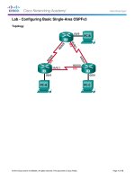
Lab – Configuring Basic RIPv2 and RIPng
Topology
© 2013 Cisco and/or its affiliates. All rights reserved. This document is Cisco Public.
Page 1 of 13
Lab – Configuring Basic RIPv2 and RIPng
Addressing Table
Device
R1
Interface
IP Address
Subnet Mask
Default Gateway
G0/1
172.30.10.1
255.255.255.0
N/A
S0/0/0 (DCE)
10.1.1.1
255.255.255.252
N/A
G0/0
209.165.201.1
255.255.255.0
N/A
S0/0/0
10.1.1.2
255.255.255.252
N/A
S0/0/1 (DCE)
10.2.2.2
255.255.255.252
N/A
G0/1
172.30.30.1
255.255.255.0
N/A
S0/0/1
10.2.2.1
255.255.255.252
N/A
S1
N/A
VLAN 1
N/A
N/A
S3
N/A
VLAN 1
N/A
N/A
PC-A
NIC
172.30.10.3
255.255.255.0
172.30.10.1
PC-B
NIC
209.165.201.2
255.255.255.0
209.165.201.1
PC-C
NIC
172.30.30.3
255.255.255.0
172.30.30.1
R2
R3
Objectives
Part 1: Build the Network and Configure Basic Device Settings
Part 2: Configure and Verify RIPv2 Routing
Configure and verify RIPv2 is running on routers.
Configure a passive interface.
Examine routing tables.
Disable automatic summarization.
Configure a default route.
Verify end-to-end connectivity.
Part 3: Configure IPv6 on Devices
Part 4: Configure and Verify RIPng Routing
Configure and verify RIPng is running on routers.
Examine routing tables.
Configure a default route.
Verify end-to-end connectivity.
Background / Scenario
RIP version 2 (RIPv2) is used for routing of IPv4 addresses in small networks. RIPv2 is a classless, distancevector routing protocol, as defined by RFC 1723. Because RIPv2 is a classless routing protocol, subnet
masks are included in the routing updates. By default, RIPv2 automatically summarizes networks at major
network boundaries. When automatic summarization has been disabled, RIPv2 no longer summarizes
networks to their classful address at boundary routers.
© 2013 Cisco and/or its affiliates. All rights reserved. This document is Cisco Public.
Page 2 of 13
Lab – Configuring Basic RIPv2 and RIPng
RIPng (RIP Next Generation) is a distance-vector routing protocol for routing IPv6 addresses, as defined by
RFC 2080. RIPng is based on RIPv2 and has the same administrative distance and 15-hop limitation.
In this lab, you will configure the network topology with RIPv2 routing, disable automatic summarization,
propagate a default route, and use CLI commands to display and verify RIP routing information. You will then
configure the network topology with IPv6 addresses, configure RIPng, propagate a default route, and use CLI
commands to display and verify RIPng routing information.
Note: The routers used with CCNA hands-on labs are Cisco 1941 Integrated Services Routers (ISRs) with
Cisco IOS Release 15.2(4)M3 (universalk9 image). The switches used are Cisco Catalyst 2960s with Cisco
IOS Release 15.0(2) (lanbasek9 image). Other routers, switches, and Cisco IOS versions can be used.
Depending on the model and Cisco IOS version, the commands available and output produced might vary
from what is shown in the labs. Refer to the Router Interface Summary Table at the end of the lab for the
correct interface identifiers.
Note: Make sure that the routers and switches have been erased and have no startup configurations. If you
are unsure, contact your instructor.
Required Resources
3 Routers (Cisco 1941 with Cisco IOS Release 15.2(4)M3 universal image or comparable)
2 Switches (Cisco 2960 with Cisco IOS Release 15.0(2) lanbasek9 image or comparable)
3 PCs (Windows 7, Vista, or XP with terminal emulation program, such as Tera Term)
Console cables to configure the Cisco IOS devices via the console ports
Ethernet and Serial cables as shown in the topology
Part 1: Build the Network and Configure Basic Device Settings
In Part 1, you will set up the network topology and configure basic settings.
Step 1: Cable the network as shown in the topology.
Step 2: Initialize and reload the router and switch.
Step 3: Configure basic settings for each router and switch.
a. Disable DNS lookup.
b. Configure device names as shown in the topology.
c.
Configure password encryption.
d. Assign class as the privileged EXEC password.
e. Assign cisco as the console and vty passwords.
f.
Configure a MOTD banner to warn users that unauthorized access is prohibited.
g. Configure logging synchronous for the console line.
h. Configure the IP address listed in the Addressing Table for all interfaces.
i.
Configure a description to each interface with an IP address.
j.
Configure the clock rate if applicable to the DCE serial interface.
k.
Copy the running-configuration to the startup-configuration.
© 2013 Cisco and/or its affiliates. All rights reserved. This document is Cisco Public.
Page 3 of 13
Lab – Configuring Basic RIPv2 and RIPng
Step 4: Configure PC hosts.
Refer to the Addressing Table for PC host address information.
Step 5: Test connectivity.
At this point, the PCs are unable to ping each other.
a. Each workstation should be able to ping the attached router. Verify and troubleshoot if necessary.
b. The routers should be able to ping one another. Verify and troubleshoot if necessary.
Part 2: Configure and Verify RIPv2 Routing
In Part 2, you will configure RIPv2 routing on all routers in the network and then verify that routing tables are
updated correctly. After RIPv2 has been verified, you will disable automatic summarization, configure a
default route, and verify end-to-end connectivity.
Step 1: Configure RIPv2 routing.
a. On R1, configure RIPv2 as the routing protocol and advertise the appropriate networks.
R1# config t
R1(config)# router
R1(config-router)#
R1(config-router)#
R1(config-router)#
R1(config-router)#
rip
version 2
passive-interface g0/1
network 172.30.0.0
network 10.0.0.0
The passive-interface command stops routing updates out the specified interface. This process prevents
unnecessary routing traffic on the LAN. However, the network that the specified interface belongs to is
still advertised in routing updates that are sent out across other interfaces.
b. Configure RIPv2 on R3 and use the network statement to add appropriate networks and prevent routing
updates on the LAN interface.
c.
Configure RIPv2 on R2. Do not advertise the 209.165.201.0 network.
Note: It is not necessary to make the G0/0 interface passive on R2 because the network associated with
this interface is not being advertised.
Step 2: Examine current state of network.
a. The status of the two serial links can quickly be verified using the show ip interface brief command on
R2.
R2# show ip interface brief
Interface
Embedded-Service-Engine0/0
GigabitEthernet0/0
GigabitEthernet0/1
Serial0/0/0
Serial0/0/1
IP-Address
unassigned
209.165.201.1
unassigned
10.1.1.2
10.2.2.2
OK?
YES
YES
YES
YES
YES
Method
unset
manual
unset
manual
manual
Status
Protocol
administratively down down
up
up
administratively down down
up
up
up
up
b. Check connectivity between PCs.
From PC-A, is it possible to ping PC-B?
Why?
From PC-A, is it possible to ping PC-C?
Why?
© 2013 Cisco and/or its affiliates. All rights reserved. This document is Cisco Public.
Page 4 of 13
Lab – Configuring Basic RIPv2 and RIPng
c.
From PC-C, is it possible to ping PC-B?
Why?
From PC-C, is it possible to ping PC-A?
Why?
Verify that RIPv2 is running on the routers.
You can use the debug ip rip, show ip protocols, and show run commands to confirm that RIPv2 is
running. The show ip protocols command output for R1 is shown below.
R1# show ip protocols
Routing Protocol is "rip"
Outgoing update filter list for all interfaces is not set
Incoming update filter list for all interfaces is not set
Sending updates every 30 seconds, next due in 7 seconds
Invalid after 180 seconds, hold down 180, flushed after 240
Redistributing: rip
Default version control: send version 2, receive 2
Interface
Send Recv Triggered RIP Key-chain
Serial0/0/0
2
2
Automatic network summarization is in effect
Maximum path: 4
Routing for Networks:
10.0.0.0
172.30.0.0
Passive Interface(s):
GigabitEthernet0/1
Routing Information Sources:
Gateway
Distance
Last Update
10.1.1.2
120
Distance: (default is 120)
When issuing the debug ip rip command on R2, what information is provided that confirms RIPv2 is
running?
When you are finished observing the debugging outputs, issue the undebug all command at the
privileged EXEC prompt.
When issuing the show run command on R3, what information is provided that confirms RIPv2 is
running?
d. Examine the automatic summarization of routes.
The LANs connected to R1 and R3 are composed of discontiguous networks. R2 displays two equal-cost
paths to the 172.30.0.0/16 network in the routing table. R2 displays only the major classful network
address of 172.30.0.0 and does not display any of the subnets for this network.
R2# show ip route
<Output omitted>
10.0.0.0/8 is variably subnetted, 4 subnets, 2 masks
C
10.1.1.0/30 is directly connected, Serial0/0/0
L
10.1.1.2/32 is directly connected, Serial0/0/0
C
10.2.2.0/30 is directly connected, Serial0/0/1
© 2013 Cisco and/or its affiliates. All rights reserved. This document is Cisco Public.
Page 5 of 13
Lab – Configuring Basic RIPv2 and RIPng
L
R
C
L
10.2.2.2/32 is directly connected, Serial0/0/1
172.30.0.0/16 [120/1] via 10.2.2.1, 00:00:23, Serial0/0/1
[120/1] via 10.1.1.1, 00:00:09, Serial0/0/0
209.165.201.0/24 is variably subnetted, 2 subnets, 2 masks
209.165.201.0/24 is directly connected, GigabitEthernet0/0
209.165.201.1/32 is directly connected, GigabitEthernet0/0
R1 displays only its own subnets for the 172.30.0.0 network. R1 does not have any routes for the
172.30.0.0 subnets on R3.
R1# show ip route
<Output omitted>
10.0.0.0/8 is variably subnetted, 3 subnets, 2 masks
C
10.1.1.0/30 is directly connected, Serial0/0/0
L
10.1.1.1/32 is directly connected, Serial0/0/0
R
10.2.2.0/30 [120/1] via 10.1.1.2, 00:00:21, Serial0/0/0
172.30.0.0/16 is variably subnetted, 2 subnets, 2 masks
C
172.30.10.0/24 is directly connected, GigabitEthernet0/1
L
172.30.10.1/32 is directly connected, GigabitEthernet0/1
R3 only displays its own subnets for the 172.30.0.0 network. R3 does not have any routes for the
172.30.0.0 subnets on R1.
R3# show ip route
<Output omitted>
10.0.0.0/8 is variably subnetted, 3 subnets, 2 masks
C
10.2.2.0/30 is directly connected, Serial0/0/1
L
10.2.2.1/32 is directly connected, Serial0/0/1
R
10.1.1.0/30 [120/1] via 10.2.2.2, 00:00:23, Serial0/0/1
172.30.0.0/16 is variably subnetted, 2 subnets, 2 masks
C
172.30.30.0/24 is directly connected, GigabitEthernet0/1
L
172.30.30.1/32 is directly connected, GigabitEthernet0/1
Use the debug ip rip command on R2 to determine the routes received in the RIP updates from R3 and
list them here.
R3 is not sending any of the 172.30.0.0 subnets, only the summarized route of 172.30.0.0/16, including
the subnet mask. Therefore, the routing tables on R1 and R2 do not display the 172.30.0.0 subnets on
R3.
Step 3: Disable automatic summarization.
a. The no auto-summary command is used to turn off automatic summarization in RIPv2. Disable auto
summarization on all routers. The routers will no longer summarize routes at major classful network
boundaries. R1 is shown here as an example.
R1(config)# router rip
R1(config-router)# no auto-summary
b. Issue the clear ip route * command to clear the routing table.
R1(config-router)# end
R1# clear ip route *
© 2013 Cisco and/or its affiliates. All rights reserved. This document is Cisco Public.
Page 6 of 13
Lab – Configuring Basic RIPv2 and RIPng
c.
Examine the routing tables. Remember will it take some time to converge the routing tables after clearing
them.
The LAN subnets connected to R1 and R3 should now be included in all three routing tables.
R2# show ip route
<Output omitted>
Gateway of last resort is not set
C
L
C
L
R
R
R
C
L
10.0.0.0/8 is variably subnetted, 4 subnets, 2 masks
10.1.1.0/30 is directly connected, Serial0/0/0
10.1.1.2/32 is directly connected, Serial0/0/0
10.2.2.0/30 is directly connected, Serial0/0/1
10.2.2.2/32 is directly connected, Serial0/0/1
172.30.0.0/16 is variably subnetted, 3 subnets, 2 masks
172.30.0.0/16 [120/1] via 10.2.2.1, 00:01:01, Serial0/0/1
[120/1] via 10.1.1.1, 00:01:15, Serial0/0/0
172.30.10.0/24 [120/1] via 10.1.1.1, 00:00:21, Serial0/0/0
172.30.30.0/24 [120/1] via 10.2.2.1, 00:00:04, Serial0/0/1
209.165.201.0/24 is variably subnetted, 2 subnets, 2 masks
209.165.201.0/24 is directly connected, GigabitEthernet0/0
209.165.201.1/32 is directly connected, GigabitEthernet0/0
R1# show ip route
<Output omitted>
Gateway of last resort is not set
C
L
R
C
L
R
10.0.0.0/8 is variably subnetted, 3 subnets, 2 masks
10.1.1.0/30 is directly connected, Serial0/0/0
10.1.1.1/32 is directly connected, Serial0/0/0
10.2.2.0/30 [120/1] via 10.1.1.2, 00:00:12, Serial0/0/0
172.30.0.0/16 is variably subnetted, 3 subnets, 2 masks
172.30.10.0/24 is directly connected, GigabitEthernet0/1
172.30.10.1/32 is directly connected, GigabitEthernet0/1
172.30.30.0/24 [120/2] via 10.1.1.2, 00:00:12, Serial0/0/0
R3# show ip route
<Output omitted>
10.0.0.0/8 is variably subnetted, 3 subnets, 2 masks
C
10.2.2.0/30 is directly connected, Serial0/0/1
L
10.2.2.1/32 is directly connected, Serial0/0/1
R
10.1.1.0/30 [120/1] via 10.2.2.2, 00:00:23, Serial0/0/1
172.30.0.0/16 is variably subnetted, 2 subnets, 2 masks
C
172.30.30.0/24 is directly connected, GigabitEthernet0/1
L
172.30.30.1/32 is directly connected, GigabitEthernet0/1
R
172.30.10.0 [120/2] via 10.2.2.2, 00:00:16, Serial0/0/1
d. Use the debug ip rip command on R2 to exam the RIP updates.
R2# debug ip rip
After 60 seconds, issue the no debug ip rip command.
© 2013 Cisco and/or its affiliates. All rights reserved. This document is Cisco Public.
Page 7 of 13
Lab – Configuring Basic RIPv2 and RIPng
What routes are in the RIP updates that are received from R3?
Are the subnet masks now included in the routing updates?
Step 4: Configure and redistribute a default route for Internet access.
a. From R2, create a static route to network 0.0.0.0 0.0.0.0, using the ip route command. This forwards any
unknown destination address traffic to the R2 G0/0 toward PC-B, simulating the Internet by setting a
Gateway of Last Resort on the R2 router.
R2(config)# ip route 0.0.0.0 0.0.0.0 209.165.201.2
b. R2 will advertise a route to the other routers if the default-information originate command is added to
its RIP configuration.
R2(config)# router rip
R2(config-router)# default-information originate
Step 5: Verify the routing configuration.
a. View the routing table on R1.
R1# show ip route
<Output omitted>
Gateway of last resort is 10.1.1.2 to network 0.0.0.0
R*
C
L
R
C
L
R
0.0.0.0/0 [120/1] via 10.1.1.2, 00:00:13, Serial0/0/0
10.0.0.0/8 is variably subnetted, 3 subnets, 2 masks
10.1.1.0/30 is directly connected, Serial0/0/0
10.1.1.1/32 is directly connected, Serial0/0/0
10.2.2.0/30 [120/1] via 10.1.1.2, 00:00:13, Serial0/0/0
172.30.0.0/16 is variably subnetted, 3 subnets, 2 masks
172.30.10.0/24 is directly connected, GigabitEthernet0/1
172.30.10.1/32 is directly connected, GigabitEthernet0/1
172.30.30.0/24 [120/2] via 10.1.1.2, 00:00:13, Serial0/0/0
How can you tell from the routing table that the subnetted network shared by R1 and R3 has a pathway
for Internet traffic?
b. View the routing table on R2.
How is the pathway for Internet traffic provided in its routing table?
Step 6: Verify connectivity.
a. Simulate sending traffic to the Internet by pinging from PC-A and PC-C to 209.165.201.2.
Were the pings successful?
© 2013 Cisco and/or its affiliates. All rights reserved. This document is Cisco Public.
Page 8 of 13
Lab – Configuring Basic RIPv2 and RIPng
b. Verify that hosts within the subnetted network can reach each other by pinging between PC-A and PC-C.
Were the pings successful?
Note: It may be necessary to disable the PCs firewall.
Part 3: Configure IPv6 on Devices
In Part 3, you will configure all interfaces with IPv6 addresses and verify connectivity.
Addressing Table
Device
Interface
IPv6 Address / Prefix Length
Default Gateway
G0/1
2001:DB8:ACAD:A::1/64
FE80::1 link-local
N/A
S0/0/0
2001:DB8:ACAD:12::1/64
FE80::1 link-local
N/A
G0/0
2001:DB8:ACAD:B::2/64
FE80::2 link-local
N/A
S0/0/0
2001:DB8:ACAD:12::2/64
FE80::2 link-local
N/A
S0/0/1
2001:DB8:ACAD:23::2/64
FE80::2 link-local
N/A
G0/1
2001:DB8:ACAD:C::3/64
FE80::3 link-local
N/A
S0/0/1
2001:DB8:ACAD:23::3/64
FE80::3 link-local
N/A
PC-A
NIC
2001:DB8:ACAD:A::A/64
FE80::1
PC-B
NIC
2001:DB8:ACAD:B::B/64
FE80::2
PC-C
NIC
2001:DB8:ACAD:C::C/64
FE80::3
R1
R2
R3
Step 1: Configure PC hosts.
Refer to the Addressing Table for PC host address information.
Step 2: Configure IPv6 on routers.
Note: Assigning an IPv6 address in addition to an IPv4 address on an interface is known as dual stacking.
This is because both IPv4 and IPv6 protocol stacks are active.
a. For each router interface, assign the global and link local address from the Addressing Table.
b. Enable IPv6 routing on each router.
c.
Enter the appropriate command to verify IPv6 addresses and link status. Write the command in the space
below.
© 2013 Cisco and/or its affiliates. All rights reserved. This document is Cisco Public.
Page 9 of 13
Lab – Configuring Basic RIPv2 and RIPng
d. Each workstation should be able to ping the attached router. Verify and troubleshoot if necessary.
e. The routers should be able to ping one another. Verify and troubleshoot if necessary.
Part 4: Configure and Verify RIPng Routing
In Part 4, you will configure RIPng routing on all routers, verify that routing tables are updated correctly,
configure and distribute a default route, and verify end-to-end connectivity.
Step 1: Configure RIPng routing.
With IPv6, it is common to have multiple IPv6 addresses configured on an interface. The network statement
has been eliminated in RIPng. RIPng routing is enabled at the interface level instead, and is identified by a
locally significant process name as multiple processes can be created with RIPng.
a. Issue the ipv6 rip Test1 enable command for each interface on R1 that is to participate in RIPng routing,
where Test1 is the locally significant process name.
R1(config)#
R1(config)#
R1(config)#
R1(config)#
interface g0/1
ipv6 rip Test1 enable
interface s0/0/0
ipv6 rip Test1 enable
b. Configure RIPng for the serial interfaces on R2 with Test2 as the process name. Do not configure for the
G0/0 interface.
c.
Configure RIPng for each interface on R3 with Test3 as the process name.
d. Verify that RIPng is running on the routers.
The show ipv6 protocols, show run, show ipv6 rip database, and show ipv6 rip process name
commands can all be used to confirm that RIPng is running. On R1, issue the show ipv6 protocols
command.
R1# show ipv6 protocols
IPv6 Routing Protocol is "connected"
IPv6 Routing Protocol is "ND"
IPv6 Routing Protocol is "rip Test1"
Interfaces:
Serial0/0/0
GigabitEthernet0/1
Redistribution:
None
How is the RIPng listed in the output?
e. Issue the show ipv6 rip Test1 command.
R1# show ipv6 rip Test1
RIP process "Test1", port 521, multicast-group FF02::9, pid 314
Administrative distance is 120. Maximum paths is 16
Updates every 30 seconds, expire after 180
Holddown lasts 0 seconds, garbage collect after 120
Split horizon is on; poison reverse is off
Default routes are not generated
Periodic updates 1, trigger updates 0
Full Advertisement 0, Delayed Events 0
Interfaces:
© 2013 Cisco and/or its affiliates. All rights reserved. This document is Cisco Public.
Page 10 of 13
Lab – Configuring Basic RIPv2 and RIPng
GigabitEthernet0/1
Serial0/0/0
Redistribution:
None
How are RIPv2 and RIPng similar?
f.
Inspect the IPv6 routing table on each router. Write the appropriate command used to view the routing
table in the space below.
On R1, how many routes have been learned by RIPng?
On R2, how many routes have been learned by RIPng?
On R3, how many routes have been learned by RIPng?
g. Check connectivity between PCs.
From PC-A, is it possible to ping PC-B?
From PC-A, is it possible to ping PC-C?
From PC-C, is it possible to ping PC-B?
From PC-C, is it possible to ping PC-A?
Why are some pings successful and others not?
Step 2: Configure and redistribute a default route.
a. From R2, create a static default route to network ::0/64 using the ipv6 route command, and the IPv6
address of PC-B. This forwards any unknown destination address traffic to the R2 G0/0 interface toward
PC-B, simulating the Internet. Write the command used in the space below.
b. Static routes can be included in RIPng updates by using the ipv6 rip process name default-information
originate command in interface configuration mode. Configure the serial links on R2 to send the default
route in RIPng updates.
R2(config)# int
R2(config-rtr)#
R2(config)# int
R2(config-rtr)#
s0/0/0
ipv6 rip Test2 default-information originate
s0/0/1
ipv6 rip Test2 default-information originate
Step 3: Verify the routing configuration.
a. View the IPv6 routing table on R2.
R2# show ipv6 route
IPv6 Routing Table - 10 entries
Codes: C - Connected, L - Local, S - Static, R - RIP, B - BGP
U - Per-user Static route, M - MIPv6
I1 - ISIS L1, I2 - ISIS L2, IA - ISIS interarea, IS - ISIS summary
O - OSPF intra, OI - OSPF inter, OE1 - OSPF ext 1, OE2 - OSPF ext 2
© 2013 Cisco and/or its affiliates. All rights reserved. This document is Cisco Public.
Page 11 of 13
Lab – Configuring Basic RIPv2 and RIPng
S
R
C
L
R
C
L
C
L
L
ON1 - OSPF NSSA ext 1, ON2 - OSPF NSSA ext 2
D - EIGRP, EX - EIGRP external
::/64 [1/0]
via 2001:DB8:ACAD:B::B
2001:DB8:ACAD:A::/64 [120/2]
via FE80::1, Serial0/0/0
2001:DB8:ACAD:B::/64 [0/0]
via ::, GigabitEthernet0/1
2001:DB8:ACAD:B::2/128 [0/0]
via ::, GigabitEthernet0/1
2001:DB8:ACAD:C::/64 [120/2]
via FE80::3, Serial0/0/1
2001:DB8:ACAD:12::/64 [0/0]
via ::, Serial0/0/0
2001:DB8:ACAD:12::2/128 [0/0]
via ::, Serial0/0/0
2001:DB8:ACAD:23::/64 [0/0]
via ::, Serial0/0/1
2001:DB8:ACAD:23::2/128 [0/0]
via ::, Serial0/0/1
FF00::/8 [0/0]
via ::, Null0
How can you tell from the routing table that R2 has a pathway for Internet traffic?
b. View the routing tables on R1 and R3.
How is the pathway for Internet traffic provided in their routing tables?
Step 4: Verify connectivity.
Simulate sending traffic to the Internet by pinging from PC-A and PC-C to 2001:DB8:ACAD:B::B/64.
Were the pings successful?
Reflection
1. Why would you turn off automatic summarization for RIPv2?
2. In both scenarios, how did R1 and R3 learn the pathway to the Internet?
3. How are configuring RIPv2 and RIPng different?
© 2013 Cisco and/or its affiliates. All rights reserved. This document is Cisco Public.
Page 12 of 13
Lab – Configuring Basic RIPv2 and RIPng
Router Interface Summary Table
Router Interface Summary
Router Model
Ethernet Interface #1
Ethernet Interface #2
Serial Interface #1
Serial Interface #2
1800
Fast Ethernet 0/0
(F0/0)
Fast Ethernet 0/1
(F0/1)
Serial 0/0/0 (S0/0/0)
Serial 0/0/1 (S0/0/1)
1900
Gigabit Ethernet 0/0
(G0/0)
Gigabit Ethernet 0/1
(G0/1)
Serial 0/0/0 (S0/0/0)
Serial 0/0/1 (S0/0/1)
2801
Fast Ethernet 0/0
(F0/0)
Fast Ethernet 0/1
(F0/1)
Serial 0/1/0 (S0/1/0)
Serial 0/1/1 (S0/1/1)
2811
Fast Ethernet 0/0
(F0/0)
Fast Ethernet 0/1
(F0/1)
Serial 0/0/0 (S0/0/0)
Serial 0/0/1 (S0/0/1)
2900
Gigabit Ethernet 0/0
(G0/0)
Gigabit Ethernet 0/1
(G0/1)
Serial 0/0/0 (S0/0/0)
Serial 0/0/1 (S0/0/1)
Note: To find out how the router is configured, look at the interfaces to identify the type of router and how many
interfaces the router has. There is no way to effectively list all the combinations of configurations for each router
class. This table includes identifiers for the possible combinations of Ethernet and Serial interfaces in the device.
The table does not include any other type of interface, even though a specific router may contain one. An
example of this might be an ISDN BRI interface. The string in parenthesis is the legal abbreviation that can be
used in Cisco IOS commands to represent the interface.
© 2013 Cisco and/or its affiliates. All rights reserved. This document is Cisco Public.
Page 13 of 13