10 2 3 5 lab configuring stateless and stateful DHCPv6 kho tài liệu bách khoa
Bạn đang xem bản rút gọn của tài liệu. Xem và tải ngay bản đầy đủ của tài liệu tại đây (491.81 KB, 14 trang )
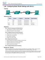
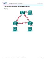
Lab – Configuring Stateless and Stateful DHCPv6
Topology
Addressing Table
Device
Interface
IPv6 Address
Prefix Length
Default Gateway
R1
G0/1
2001:DB8:ACAD:A::1
64
N/A
S1
VLAN 1
Assigned by SLAAC
64
Assigned by SLAAC
PC-A
NIC
Assigned by SLAAC and DHCPv6
64
Assigned by R1
Objectives
Part 1: Build the Network and Configure Basic Device Settings
Part 2: Configure the Network for SLAAC
Part 3: Configure the Network for Stateless DHCPv6
Part 4: Configure the Network for Stateful DHCPv6
Background / Scenario
The dynamic assignment of IPv6 global unicast addresses can be configured in three ways:
Stateless Address Autoconfiguration (SLAAC) only
Stateless Dynamic Host Configuration Protocol for IPv6 (DHCPv6)
Stateful DHCPv6
With SLAAC (pronounced slack), a DHCPv6 server is not needed for hosts to acquire IPv6 addresses. It can
be used to receive additional information that the host needs, such as the domain name and the domain
name server (DNS) address. When SLAAC is used to assign the IPv6 host addresses and DHCPv6 is used to
assign other network parameters, it is called Stateless DHCPv6.
With Stateful DHCPv6, the DHCP server assigns all information, including the host IPv6 address.
Determination of how hosts obtain their dynamic IPv6 addressing information is dependent on flag settings
contained within the router advertisement (RA) messages.
In this lab, you will initially configure the network to use SLAAC. After connectivity has been verified, you will
configure DHCPv6 settings and change the network to use Stateless DHCPv6. After verification that Stateless
DHCPv6 is functioning correctly, you will change the configuration on R1 to use Stateful DHCPv6. Wireshark
will be used on PC-A to verify all three dynamic network configurations.
Note: The routers used with CCNA hands-on labs are Cisco 1941 Integrated Services Routers (ISRs) with
Cisco IOS Release 15.2(4)M3 (universalk9 image). The switches used are Cisco Catalyst 2960s with Cisco
IOS Release 15.0(2) (lanbasek9 image). Other routers, switches and Cisco IOS versions can be used.
Depending on the model and Cisco IOS version, the commands available and output produced might vary
© 2013 Cisco and/or its affiliates. All rights reserved. This document is Cisco Public.
Page 1 of 14
Lab – Configuring Stateless and Stateful DHCPv6
from what is shown in the labs. Refer to the Router Interface Summary Table at the end of this lab for the
correct interface identifiers.
Note: Make sure that the router and switch have been erased and have no startup configurations. If you are
unsure, contact your instructor.
Note: The default bias template (used by the Switch Database Manager (SDM)) does not provide IPv6
address capabilities. Verify that SDM is using either the dual-ipv4-and-ipv6 template or the lanbase-routing
template. The new template will be used after reboot even if the config is not saved.
S1# show sdm prefer
Follow these steps to assign the dual-ipv4-and-ipv6 template as the default SDM template:
S1# config t
S1(config)# sdm prefer dual-ipv4-and-ipv6 default
S1(config)# end
S1# reload
Required Resources
1 Router (Cisco 1941 with Cisco IOS Release 15.2(4)M3 universal image or comparable)
1 Switch (Cisco 2960 with Cisco IOS Release 15.0(2) lanbasek9 image or comparable)
1 PC (Windows 7 or Vista with Wireshark and terminal emulation program, such as Tera Term)
Console cables to configure the Cisco IOS devices via the console ports
Ethernet cables as shown in the topology
Note: DHCPv6 client services are disabled on Windows XP. It is recommended to use a Windows 7 host for
this lab.
Part 1: Build the Network and Configure Basic Device Settings
In Part 1, you will set up the network topology and configure basic settings, such as device names, passwords
and interface IP addresses.
Step 1: Cable the network as shown in the topology.
Step 2: Initialize and reload the router and switch as necessary.
Step 3: Configure R1.
a. Disable DNS lookup.
b. Configure the device name.
c.
Encrypt plain text passwords.
d. Create a MOTD banner warning users that unauthorized access is prohibited.
e. Assign class as the encrypted privileged EXEC mode password.
f.
Assign cisco as the console and vty password and enable login.
g. Set console logging to synchronous mode.
h. Save the running configuration to the startup configuration.
© 2013 Cisco and/or its affiliates. All rights reserved. This document is Cisco Public.
Page 2 of 14
Lab – Configuring Stateless and Stateful DHCPv6
Step 4: Configure S1.
a. Disable DNS lookup.
b. Configure the device name.
c.
Encrypt plain text passwords.
d. Create a MOTD banner warning users that unauthorized access is prohibited.
e. Assign class as the encrypted privileged EXEC mode password.
f.
Assign cisco as the console and vty password and enable login.
g. Set console logging to synchronous mode.
h. Administratively disable all inactive interfaces.
i.
Save running configuration to the startup configuration.
Part 2: Configure the Network for SLAAC
Step 1: Prepare PC-A.
a. Verify that the IPv6 protocol has been enabled on the Local Area Connection Properties window. If the
Internet Protocol Version 6 (TCP/IPv6) check box is not checked, click to enable it.
b. Start a Wireshark capture of traffic on the NIC.
© 2013 Cisco and/or its affiliates. All rights reserved. This document is Cisco Public.
Page 3 of 14
Lab – Configuring Stateless and Stateful DHCPv6
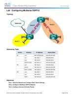
c.
Filter the data capture to see only RA messages. This can be done by filtering on IPv6 packets with a
destination address of FF02::1, which is the all-unicast client group address. The filter entry used with
Wireshark is ipv6.dst==ff02::1, as shown here.
Step 2: Configure R1.
a. Enable IPv6 unicast routing.
b. Assign the IPv6 unicast address to interface G0/1 according to the Addressing Table.
c.
Assign FE80::1 as the IPv6 link-local address for interface G0/1.
d. Activate interface G0/1.
Step 3: Verify that R1 is part of the all-router multicast group.
Use the show ipv6 interface g0/1 command to verify that G0/1 is part of the All-router multicast group
(FF02::2). RA messages are not sent out G0/1 without that group assignment.
R1# show ipv6 interface g0/1
GigabitEthernet0/1 is up, line protocol is up
IPv6 is enabled, link-local address is FE80::1
No Virtual link-local address(es):
Global unicast address(es):
2001:DB8:ACAD:A::1, subnet is 2001:DB8:ACAD:A::/64
Joined group address(es):
FF02::1
FF02::2
FF02::1:FF00:1
MTU is 1500 bytes
ICMP error messages limited to one every 100 milliseconds
ICMP redirects are enabled
ICMP unreachables are sent
ND DAD is enabled, number of DAD attempts: 1
ND reachable time is 30000 milliseconds (using 30000)
ND advertised reachable time is 0 (unspecified)
ND advertised retransmit interval is 0 (unspecified)
ND router advertisements are sent every 200 seconds
ND router advertisements live for 1800 seconds
ND advertised default router preference is Medium
Hosts use stateless autoconfig for addresses.
Step 4: Configure S1.
Use the ipv6 address autoconfig command on VLAN 1 to obtain an IPv6 address through SLAAC.
S1(config)# interface vlan 1
S1(config-if)# ipv6 address autoconfig
S1(config-if)# end
© 2013 Cisco and/or its affiliates. All rights reserved. This document is Cisco Public.
Page 4 of 14
Lab – Configuring Stateless and Stateful DHCPv6
Step 5: Verify that SLAAC provided a unicast address to S1.
Use the show ipv6 interface command to verify that SLAAC provided a unicast address to VLAN1 on S1.
S1# show ipv6 interface
Vlan1 is up, line protocol is up
IPv6 is enabled, link-local address is FE80::ED9:96FF:FEE8:8A40
No Virtual link-local address(es):
Stateless address autoconfig enabled
Global unicast address(es):
2001:DB8:ACAD:A:ED9:96FF:FEE8:8A40, subnet is 2001:DB8:ACAD:A::/64 [EUI/CAL/PRE]
valid lifetime 2591988 preferred lifetime 604788
Joined group address(es):
FF02::1
FF02::1:FFE8:8A40
MTU is 1500 bytes
ICMP error messages limited to one every 100 milliseconds
ICMP redirects are enabled
ICMP unreachables are sent
Output features: Check hwidb
ND DAD is enabled, number of DAD attempts: 1
ND reachable time is 30000 milliseconds (using 30000)
ND NS retransmit interval is 1000 milliseconds
Default router is FE80::1 on Vlan1
Step 6: Verify that SLAAC provided IPv6 address information on PC-A.
a. From a command prompt on PC-A, issue the ipconfig /all command. Verify that PC-A is showing an IPv6
address with the 2001:db8:acad:a::/64 prefix. The Default Gateway should have the FE80::1 address.
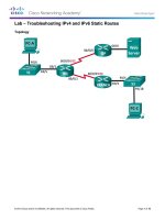
b. From Wireshark, look at one of the RA messages that were captured. Expand the Internet Control
Message Protocol v6 layer to view the Flags and Prefix information. The first two flags control DHCPv6
usage and are not set if DHCPv6 is not configured. The prefix information is also contained within this RA
message.
© 2013 Cisco and/or its affiliates. All rights reserved. This document is Cisco Public.
Page 5 of 14
Lab – Configuring Stateless and Stateful DHCPv6
Part 3: Configure the Network for Stateless DHCPv6
Step 1: Configure an IPv6 DHCP server on R1.
a. Create an IPv6 DHCP pool.
R1(config)# ipv6 dhcp pool IPV6POOL-A
b. Assign a domain name to the pool.
R1(config-dhcpv6)# domain-name ccna-statelessDHCPv6.com
c.
Assign a DNS server address.
R1(config-dhcpv6)# dns-server 2001:db8:acad:a::abcd
R1(config-dhcpv6)# exit
d. Assign the DHCPv6 pool to the interface.
R1(config)# interface g0/1
R1(config-if)# ipv6 dhcp server IPV6POOL-A
e. Set the DHCPv6 network discovery (ND) other-config-flag.
R1(config-if)# ipv6 nd other-config-flag
R1(config-if)# end
Step 2: Verify DHCPv6 settings on interface G0/1 on R1.
Use the show ipv6 interface g0/1 command to verify that the interface is now part of the IPv6 multicast allDHCPv6-servers group (FF02::1:2). The last line of the output from this show command verifies that the
other-config-flag has been set.
R1# show ipv6 interface g0/1
GigabitEthernet0/1 is up, line protocol is up
© 2013 Cisco and/or its affiliates. All rights reserved. This document is Cisco Public.
Page 6 of 14
Lab – Configuring Stateless and Stateful DHCPv6
IPv6 is enabled, link-local address is FE80::1
No Virtual link-local address(es):
Global unicast address(es):
2001:DB8:ACAD:A::1, subnet is 2001:DB8:ACAD:A::/64
Joined group address(es):
FF02::1
FF02::2
FF02::1:2
FF02::1:FF00:1
FF05::1:3
MTU is 1500 bytes
ICMP error messages limited to one every 100 milliseconds
ICMP redirects are enabled
ICMP unreachables are sent
ND DAD is enabled, number of DAD attempts: 1
ND reachable time is 30000 milliseconds (using 30000)
ND advertised reachable time is 0 (unspecified)
ND advertised retransmit interval is 0 (unspecified)
ND router advertisements are sent every 200 seconds
ND router advertisements live for 1800 seconds
ND advertised default router preference is Medium
Hosts use stateless autoconfig for addresses.
Hosts use DHCP to obtain other configuration.
Step 3: View network changes to PC-A.
Use the ipconfig /all command to review the network changes. Notice that additional information, including
the domain name and DNS server information, has been retrieved from the DHCPv6 server. However, the
IPv6 global unicast and link-local addresses were obtained previously from SLAAC.
© 2013 Cisco and/or its affiliates. All rights reserved. This document is Cisco Public.
Page 7 of 14
Lab – Configuring Stateless and Stateful DHCPv6
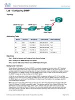
Step 4: View the RA messages in Wireshark.
Scroll down to the last RA message that is displayed in Wireshark and expand it to view the ICMPv6 flag
settings. Notice that the other configuration flag is set to 1.
Step 5: Verify that PC-A did not obtain its IPv6 address from a DHCPv6 server.
Use the show ipv6 dhcp binding and show ipv6 dhcp pool commands to verify that PC-A did not obtain an
IPv6 address from the DHCPv6 pool.
R1# show ipv6 dhcp binding
R1# show ipv6 dhcp pool
DHCPv6 pool: IPV6POOL-A
DNS server: 2001:DB8:ACAD:A::ABCD
Domain name: ccna-statelessDHCPv6.com
Active clients: 0
Step 6: Reset PC-A IPv6 network settings.
a. Shut down interface F0/6 on S1.
Note: Shutting down the interface F0/6 prevents PC-A from receiving a new IPv6 address before you
reconfigure R1 for Stateful DHCPv6 in Part 4.
S1(config)# interface f0/6
S1(config-if)# shutdown
b. Stop Wireshark capture of traffic on the PC-A NIC.
c.
Reset the IPv6 settings on PC-A to remove the Stateless DHCPv6 settings.
1) Open the Local Area Connection Properties window, deselect the Internet Protocol Version 6
(TCP/IPv6) check box, and click OK to accept the change.
2) Open the Local Area Connection Properties window again, click to enable the Internet Protocol
Version 6 (TCP/IPv6) check box, and then click OK to accept the change.
© 2013 Cisco and/or its affiliates. All rights reserved. This document is Cisco Public.
Page 8 of 14
Lab – Configuring Stateless and Stateful DHCPv6
Part 4: Configure the Network for Stateful DHCPv6
Step 1: Prepare PC-A.
a. Start a Wireshark capture of traffic on the NIC.
b. Filter the data capture to see only RA messages. This can be done by filtering on IPv6 packets with a
destination address of FF02::1, which is the all-unicast client group address.
Step 2: Change the DHCPv6 pool on R1.
a. Add the network prefix to the pool.
R1(config)# ipv6 dhcp pool IPV6POOL-A
R1(config-dhcpv6)# address prefix 2001:db8:acad:a::/64
b. Change the domain name to ccna-statefulDHCPv6.com.
Note: You must remove the old domain name. It is not replaced by the domain-name command.
R1(config-dhcpv6)# no domain-name ccna-statelessDHCPv6.com
R1(config-dhcpv6)# domain-name ccna-StatefulDHCPv6.com
R1(config-dhcpv6)# end
c.
Verify DHCPv6 pool settings.
R1# show ipv6 dhcp pool
DHCPv6 pool: IPV6POOL-A
Address allocation prefix: 2001:DB8:ACAD:A::/64 valid 172800 preferred 86400 (0 in
use, 0 conflicts)
DNS server: 2001:DB8:ACAD:A::ABCD
Domain name: ccna-StatefulDHCPv6.com
Active clients: 0
d. Enter debug mode to verify the Stateful DHCPv6 address assignment.
R1# debug ipv6 dhcp detail
IPv6 DHCP debugging is on (detailed)
Step 3: Set the flag on G0/1 for Stateful DHCPv6.
Note: Shutting down the G0/1 interface before making changes ensures that an RA message is sent when
the interface is activated.
R1(config)# interface g0/1
R1(config-if)# shutdown
R1(config-if)# ipv6 nd managed-config-flag
R1(config-if)# no shutdown
R1(config-if)# end
Step 4: Enable interface F0/6 on S1.
Now that R1 has been configured for Stateful DHCPv6, you can reconnect PC-A to the network by activating
interface F0/6 on S1.
S1(config)# interface f0/6
© 2013 Cisco and/or its affiliates. All rights reserved. This document is Cisco Public.
Page 9 of 14
Lab – Configuring Stateless and Stateful DHCPv6
S1(config-if)# no shutdown
S1(config-if)# end
Step 5: Verify Stateful DHCPv6 settings on R1.
a. Issue the show ipv6 interface g0/1 command to verify that the interface is in Stateful DHCPv6 mode.
R1# show ipv6 interface g0/1
GigabitEthernet0/1 is up, line protocol is up
IPv6 is enabled, link-local address is FE80::1
No Virtual link-local address(es):
Global unicast address(es):
2001:DB8:ACAD:A::1, subnet is 2001:DB8:ACAD:A::/64
Joined group address(es):
FF02::1
FF02::2
FF02::1:2
FF02::1:FF00:1
FF05::1:3
MTU is 1500 bytes
ICMP error messages limited to one every 100 milliseconds
ICMP redirects are enabled
ICMP unreachables are sent
ND DAD is enabled, number of DAD attempts: 1
ND reachable time is 30000 milliseconds (using 30000)
ND advertised reachable time is 0 (unspecified)
ND advertised retransmit interval is 0 (unspecified)
ND router advertisements are sent every 200 seconds
ND router advertisements live for 1800 seconds
ND advertised default router preference is Medium
Hosts use DHCP to obtain routable addresses.
Hosts use DHCP to obtain other configuration.
b. In a command prompt on PC-A, type ipconfig /release6 to release the currently assigned IPv6 address.
Then type ipconfig /renew6 to request an IPv6 address from the DHCPv6 server.
c.
Issue the show ipv6 dhcp pool command to verify the number of active clients.
R1# show ipv6 dhcp pool
DHCPv6 pool: IPV6POOL-A
Address allocation prefix: 2001:DB8:ACAD:A::/64 valid 172800 preferred 86400 (1 in
use, 0 conflicts)
DNS server: 2001:DB8:ACAD:A::ABCD
Domain name: ccna-StatefulDHCPv6.com
Active clients: 1
d. Issue the show ipv6 dhcp binding command to verify that PC-A received its IPv6 unicast address from
the DHCP pool. Compare the client address to the link-local IPv6 address on PC-A using the ipconfig /all
command. Compare the address provided by the show command to the IPv6 address listed with the
ipconfig /all command on PC-A.
R1# show ipv6 dhcp binding
Client: FE80::D428:7DE2:997C:B05A
DUID: 0001000117F6723D000C298D5444
© 2013 Cisco and/or its affiliates. All rights reserved. This document is Cisco Public.
Page 10 of 14
Lab – Configuring Stateless and Stateful DHCPv6
Username : unassigned
IA NA: IA ID 0x0E000C29, T1 43200, T2 69120
Address: 2001:DB8:ACAD:A:B55C:8519:8915:57CE
preferred lifetime 86400, valid lifetime 172800
expires at Mar 07 2013 04:09 PM (171595 seconds)
e. Issue the undebug all command on R1 to stop debugging DHCPv6.
Note: Typing u all is the shortest form of this command and is useful to know if you are trying to stop
debug messages from continually scrolling down your terminal session screen. If multiple debugs are in
process, the undebug all command stops all of them.
R1# u all
All possible debugging has been turned off
f.
Review the debug messages that appeared on your R1 terminal screen.
1) Examine the solicit message from PC-A requesting network information.
*Mar 5 16:42:39.775: IPv6 DHCP: Received SOLICIT from FE80::D428:7DE2:997C:B05A on
GigabitEthernet0/1
*Mar 5 16:42:39.775: IPv6 DHCP: detailed packet contents
*Mar 5 16:42:39.775:
src FE80::D428:7DE2:997C:B05A (GigabitEthernet0/1)
*Mar 5 16:42:39.775:
dst FF02::1:2
*Mar 5 16:42:39.775:
type SOLICIT(1), xid 1039238
*Mar 5 16:42:39.775:
option ELAPSED-TIME(8), len 2
*Mar 5 16:42:39.775:
elapsed-time 6300
*Mar 5 16:42:39.775:
option CLIENTID(1), len 14
2) Examine the reply message sent back to PC-A with the DHCP network information.
*Mar 5 16:42:39.779: IPv6 DHCP: Sending REPLY to FE80::D428:7DE2:997C:B05A on
GigabitEthernet0/1
*Mar 5 16:42:39.779: IPv6 DHCP: detailed packet contents
*Mar 5 16:42:39.779:
src FE80::1
*Mar 5 16:42:39.779:
dst FE80::D428:7DE2:997C:B05A (GigabitEthernet0/1)
*Mar 5 16:42:39.779:
type REPLY(7), xid 1039238
© 2013 Cisco and/or its affiliates. All rights reserved. This document is Cisco Public.
Page 11 of 14
Lab – Configuring Stateless and Stateful DHCPv6
*Mar 5 16:42:39.779:
*Mar 5 16:42:39.779:
*Mar 5 16:42:39.779:
*Mar 5 16:42:39.779:
R1#17F6723D000C298D5444
*Mar 5 16:42:39.779:
*Mar 5 16:42:39.779:
*Mar 5 16:42:39.779:
*Mar 5 16:42:39.779:
*Mar 5 16:42:39.779:
*Mar 5 16:42:39.779:
*Mar 5 16:42:39.779:
*Mar 5 16:42:39.779:
*Mar 5 16:42:39.779:
option SERVERID(2), len 10
00030001FC994775C3E0
option CLIENTID(1), len 14
00010001
option IA-NA(3), len 40
IAID 0x0E000C29, T1 43200, T2 69120
option IAADDR(5), len 24
IPv6 address 2001:DB8:ACAD:A:B55C:8519:8915:57CE
preferred 86400, valid 172800
option DNS-SERVERS(23), len 16
2001:DB8:ACAD:A::ABCD
option DOMAIN-LIST(24), len 26
ccna-StatefulDHCPv6.com
Step 6: Verify Stateful DHCPv6 on PC-A
a. Stop the Wireshark capture on PC-A.
b. Expand the most recent RA message listed in Wireshark. Verify that the Managed address
configuration flag has been set.
c.
Change the filter in Wireshark to view DHCPv6 packets only by typing dhcpv6, and then Apply the filter.
Highlight the last DHCPv6 reply listed and expand the DHCPv6 information. Examine the DHCPv6
network information that is contained in this packet.
© 2013 Cisco and/or its affiliates. All rights reserved. This document is Cisco Public.
Page 12 of 14
Lab – Configuring Stateless and Stateful DHCPv6
Reflection
1. What IPv6 addressing method uses more memory resources on the router configured as a DHCPv6 server,
Stateless DHCPv6 or Stateful DHCPv6? Why?
2. Which type of dynamic IPv6 address assignment is recommended by Cisco, Stateless DHCPv6 or Stateful
DHCPv6?
© 2013 Cisco and/or its affiliates. All rights reserved. This document is Cisco Public.
Page 13 of 14
Lab – Configuring Stateless and Stateful DHCPv6
Router Interface Summary Table
Router Interface Summary
Router Model
Ethernet Interface #1
Ethernet Interface #2
Serial Interface #1
Serial Interface #2
1800
Fast Ethernet 0/0
(F0/0)
Fast Ethernet 0/1
(F0/1)
Serial 0/0/0 (S0/0/0)
Serial 0/0/1 (S0/0/1)
1900
Gigabit Ethernet 0/0
(G0/0)
Gigabit Ethernet 0/1
(G0/1)
Serial 0/0/0 (S0/0/0)
Serial 0/0/1 (S0/0/1)
2801
Fast Ethernet 0/0
(F0/0)
Fast Ethernet 0/1
(F0/1)
Serial 0/1/0 (S0/1/0)
Serial 0/1/1 (S0/1/1)
2811
Fast Ethernet 0/0
(F0/0)
Fast Ethernet 0/1
(F0/1)
Serial 0/0/0 (S0/0/0)
Serial 0/0/1 (S0/0/1)
2900
Gigabit Ethernet 0/0
(G0/0)
Gigabit Ethernet 0/1
(G0/1)
Serial 0/0/0 (S0/0/0)
Serial 0/0/1 (S0/0/1)
Note: To find out how the router is configured, look at the interfaces to identify the type of router and how many
interfaces the router has. There is no way to effectively list all the combinations of configurations for each router
class. This table includes identifiers for the possible combinations of Ethernet and Serial interfaces in the device.
The table does not include any other type of interface, even though a specific router may contain one. An
example of this might be an ISDN BRI interface. The string in parenthesis is the legal abbreviation that can be
used in Cisco IOS commands to represent the interface.
© 2013 Cisco and/or its affiliates. All rights reserved. This document is Cisco Public.
Page 14 of 14