10 3 1 2 lab d configure anyconnect remote access SSL VPN using ASDM kho tài liệu bách khoa
Bạn đang xem bản rút gọn của tài liệu. Xem và tải ngay bản đầy đủ của tài liệu tại đây (1006.46 KB, 29 trang )
CCNA Security
Chapter 10 – Configure AnyConnect Remote Access SSL VPN
Using ASDM
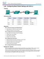
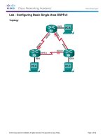
Topology
Note: ISR G1 devices use FastEthernet interfaces instead of GigabitEthernet interfaces.
© 2015 Cisco and/or its affiliates. All rights reserved. This document is Cisco Public.
Page 1 of 29
CCNA Security
Chapter 10 Lab D
IP Addressing Table
Device
Interface
IP Address
Subnet Mask
Default Gateway
Switch Port
G0/0
209.165.200.225
255.255.255.248
N/A
ASA E0/0
S0/0/0 (DCE)
10.1.1.1
255.255.255.252
N/A
N/A
S0/0/0
10.1.1.2
255.255.255.252
N/A
N/A
S0/0/1 (DCE)
10.2.2.2
255.255.255.252
N/A
N/A
G0/1
172.16.3.1
255.255.255.0
N/A
S3 F0/5
S0/0/1
10.2.2.1
255.255.255.252
N/A
N/A
VLAN 1 (E0/1)
192.168.1.1
255.255.255.0
NA
S2 F0/24
VLAN 2 (E0/0)
209.165.200.226
255.255.255.248
NA
R1 G0/0
VLAN 3 (E0/2)
192.168.2.1
255.255.255.0
NA
S1 F0/24
PC-A
NIC
192.168.2.3
255.255.255.0
192.168.2.1
S1 F0/6
PC-B
NIC
192.168.1.3
255.255.255.0
192.168.1.1
S2 F0/18
PC-C
NIC
172.16.3.3
255.255.255.0
172.16.3.1
S3 F0/18
R1
R2
R3
ASA
Objectives
Part 1: Basic Router/Switch/PC Configuration
Cable the network and clear previous device settings, as shown in the topology.
Configure basic settings for routers.
Configure PC host IP settings.
Verify connectivity.
Save the basic running configuration for each router and switch.
Part 2: Access the ASA Console and ASDM
Access the ASA console.
Clear the previous ASA configuration settings.
Bypass Setup mode.
Configure the ASA by using the CLI script.
Access ASDM.
Part 3: Configuring AnyConnect Client SSL VPN Remote Access Using ASDM
Start the VPN wizard.
Specify the VPN encryption protocol.
Specify the client image to upload to AnyConnect users.
Configure AAA local authentication.
Configure the client address assignment.
Configure the network name resolution.
© 2015 Cisco and/or its affiliates. All rights reserved. This document is Cisco Public.
Page 2 of 29
CCNA Security
Exempt address translation for VPN traffic.
Review the AnyConnect client deployment details.
Review the Summary screen and apply the configuration to the ASA.
Chapter 10 Lab D
Part 4: Connecting to an AnyConnect SSL VPN
Verify the AnyConnect client profile.
Log in from the remote host.
Perform platform detection (if required).
Perform an automatic installation of the AnyConnect VPN Client (if required).
Manually install the AnyConnect VPN Client (if required).
Confirm VPN connectivity.
Background/Scenario
In addition to stateful firewall and other security features, the ASA can provide both site-to-site and remote
access VPN functionality. The ASA provides two main deployment modes that are found in Cisco SSL remote
access VPN solutions:
Clientless SSL VPN - A clientless, browser-based VPN that lets users establish a secure, remote-access
VPN tunnel to the ASA and use a web browser and built-in SSL to protect VPN traffic. After
authentication, users are presented with a portal page and can access specific, predefined internal
resources from the portal.
Client-Based SSL VPN - A client-based VPN that provides full-tunnel SSL VPN connection, but requires
a VPN client application to be installed on the remote host. After authentication, users can access any
internal resource as if they were physically on the local network. The ASA supports both SSL and IPsec
client-based VPNs.
In Part 1 of this lab, you will configure the topology and non-ASA devices. In Part 2, you will prepare the ASA
for ASDM access. In Part 3, you will use the ASDM VPN wizard to configure an AnyConnect client-based SSL
remote access VPN. In Part 4 you will establish a connection and verify connectivity.
Your company has two locations connected to an ISP. R1 represents a CPE device managed by the ISP. R2
represents an intermediate Internet router. R3 connects users at the remote branch office to the ISP. The
ASA is an edge security device that connects the internal corporate network and DMZ to the ISP while
providing NAT services to inside hosts.
Management has asked you to provide VPN access to teleworkers using the ASA as a VPN concentrator.
They want you to test the client-based model using SSL and the Cisco AnyConnect client.
Note: The router commands and output in this lab are from a Cisco 1941 router with Cisco IOS Release
15.4(3)M2 (with a Security Technology Package license). Other routers and Cisco IOS versions can be used.
See the Router Interface Summary Table at the end of the lab to determine which interface identifiers to use
based on the equipment in the lab. Depending on the router model and Cisco IOS version, the commands
available and the output produced might vary from what is shown in this lab.
The ASA used with this lab is a Cisco model 5505 with an 8-port integrated switch, running OS version 9.2(3)
and ASDM version 7.4(1) and comes with a Base license that allows a maximum of three VLANs.
Note: Before beginning, ensure that the routers and switches have been erased and have no startup
configurations.
© 2015 Cisco and/or its affiliates. All rights reserved. This document is Cisco Public.
Page 3 of 29
CCNA Security
Chapter 10 Lab D
Required Resources
1 ASA 5505 (OS version 9.2(3) and ASDM version 7.4(1) and Base license or comparable)
3 routers (Cisco 1941 with Cisco IOS Release 15.4(3)M2 image with a Security Technology package
license)
3 switches (Cisco 2960 or comparable) (not required)
3 PCs (Windows 7 or Windows 8.1, with SSH client software installed)
Serial and Ethernet cables, as shown in the topology
Console cables to configure Cisco networking devices
Part 1: Basic Router/Switch/PC Configuration
In Part 1, you will set up the network topology and configure basic settings on the routers such as interface IP
addresses and static routing.
Note: Do not configure any ASA settings at this time.
Step 1: Cable the network and clear previous device settings.
Attach the devices shown in the topology diagram and cable as necessary. Ensure that the routers and
switches have been erased and have no startup configurations.
Step 2: Configure R1 using the CLI script.
In this step, you will use the following CLI script to configure basic settings on R1. Copy and paste the basic
configuration script commands listed below. Observe the messages as the commands are applied to ensure
that there are no warnings or errors.
Note: Depending on the router model, interfaces might be numbered differently than those listed. You might
need to alter the designations accordingly.
Note: Passwords in this task are set to a minimum of 10 characters and are relatively simple for the purposes
of performing the lab. More complex passwords are recommended in a production network.
hostname R1
security passwords min-length 10
enable algorithm-type scrypt secret cisco12345
username admin01 algorithm-type scrypt secret admin01pass
ip domain name ccnasecurity.com
line con 0
login local
exec-timeout 5 0
logging synchronous
exit
line vty 0 4
login local
transport input ssh
exec-timeout 5 0
logging synchronous
exit
interface gigabitethernet 0/0
© 2015 Cisco and/or its affiliates. All rights reserved. This document is Cisco Public.
Page 4 of 29
CCNA Security
Chapter 10 Lab D
ip address 209.165.200.225 255.255.255.248
no shut
exit
int serial 0/0/0
ip address 10.1.1.1 255.255.255.252
clock rate 2000000
no shut
exit
ip route 0.0.0.0 0.0.0.0 Serial0/0/0
crypto key generate rsa general-keys modulus 1024
Step 3: Configure R2 using the CLI script.
In this step, you will use the following CLI script to configure basic settings on R2. Copy and paste the basic
configuration script commands listed below. Observe the messages as the commands are applied to ensure
that there are no warnings or errors.
hostname R2
security passwords min-length 10
enable algorithm-type scrypt secret cisco12345
username admin01 algorithm-type scrypt secret admin01pass
ip domain name ccnasecurity.com
line con 0
login local
exec-timeout 5 0
logging synchronous
exit
line vty 0 4
login local
transport input ssh
exec-timeout 5 0
logging synchronous
exit
interface serial 0/0/0
ip address 10.1.1.2 255.255.255.252
no shut
exit
interface serial 0/0/1
ip address 10.2.2.2 255.255.255.252
clock rate 2000000
no shut
exit
ip route 209.165.200.224 255.255.255.248 Serial0/0/0
ip route 172.16.3.0 255.255.255.0 Serial0/0/1
crypto key generate rsa general-keys modulus 1024
© 2015 Cisco and/or its affiliates. All rights reserved. This document is Cisco Public.
Page 5 of 29
CCNA Security
Chapter 10 Lab D
Step 4: Configure R3 using the CLI script.
In this step, you will use the following CLI script to configure basic settings on R3. Copy and paste the basic
configuration script commands listed below. Observe the messages as the commands are applied to ensure
that there are no warnings or errors.
hostname R3
security passwords min-length 10
enable algorithm-type scrypt secret cisco12345
username admin01 algorithm-type scrypt secret admin01pass
ip domain name ccnasecurity.com
line con 0
login local
exec-timeout 5 0
logging synchronous
exit
line vty 0 4
login local
transport input ssh
exec-timeout 5 0
logging synchronous
exit
interface gigabitethernet 0/1
ip address 172.16.3.1 255.255.255.0
no shut
exit
int serial 0/0/1
ip address 10.2.2.1 255.255.255.252
no shut
exit
ip route 0.0.0.0 0.0.0.0 Serial0/0/1
crypto key generate rsa general-keys modulus 1024
Step 5: Configure PC host IP settings.
Configure a static IP address, subnet mask, and default gateway for PC-A, PC-B, and PC-C as shown in the
IP Addressing table.
Step 6: Verify connectivity.
The ASA is the focal point for the network zones, and it has not yet been configured. Therefore, there will be
no connectivity between devices that are connected to it. However, PC-C should be able to ping the R1
interface G0/0. From PC-C, ping the R1 G0/0 IP address (209.165.200.225). If these pings are unsuccessful,
troubleshoot the basic device configurations before continuing.
Note: If you can ping from PC-C to R1 G0/0 and S0/0/0, you have demonstrated that static routing is
configured and functioning correctly.
© 2015 Cisco and/or its affiliates. All rights reserved. This document is Cisco Public.
Page 6 of 29
CCNA Security
Chapter 10 Lab D
Step 7: Save the basic running configuration for each router and switch.
Part 2: Accessing the ASA Console and ASDM
Step 1: Clear the previous ASA configuration settings.
a. Use the write erase command to remove the startup-config file from flash memory.
Note: The erase startup-config IOS command is not supported on the ASA.
b. Use the reload command to restart the ASA. This causes the ASA to display in CLI Setup mode. If you
see the System config has been modified. Save? [Y]es/[N]o: message, type n, and press Enter.
Step 2: Bypass Setup mode.
When the ASA completes the reload process, it should detect that the startup configuration file is missing and
go into Setup mode. If it does not go into Setup mode, repeat Step 2.
a. When prompted to preconfigure the firewall through interactive prompts (Setup mode), respond with no.
b. Enter privileged EXEC mode with the enable command. The password should be kept blank (no
password).
Step 3: Configure the ASA by using the CLI script.
In this step, you will use a CLI script to configure basic settings, the firewall, and the DMZ.
a. Use the show run command to confirm that there is no previous configuration in the ASA other than the
defaults that the ASA automatically inserts.
b. Enter global configuration mode. When prompted to enable anonymous call-home reporting, respond no.
c.
Copy and paste the Pre-VPN Configuration Script commands listed below at the ASA global configuration
mode prompt to start configuring the SSL VPNs.
Observe the messages as the commands are applied to ensure that there are no warnings or errors. If
prompted to replace the RSA key pair, respond yes.
hostname CCNAS-ASA
domain-name ccnasecurity.com
enable password cisco12345
!
interface Ethernet0/0
switchport access vlan 2
no shut
!
interface Ethernet0/1
switchport access vlan 1
no shut
!
interface Ethernet0/2
switchport access vlan 3
no shut
!
interface Vlan1
© 2015 Cisco and/or its affiliates. All rights reserved. This document is Cisco Public.
Page 7 of 29
CCNA Security
Chapter 10 Lab D
nameif inside
security-level 100
ip address 192.168.1.1 255.255.255.0
!
interface Vlan2
nameif outside
security-level 0
ip address 209.165.200.226 255.255.255.248
!
interface Vlan3
no forward interface Vlan1
nameif dmz
security-level 70
ip address 192.168.2.1 255.255.255.0
!
object network inside-net
subnet 192.168.1.0 255.255.255.0
!
object network dmz-server
host 192.168.2.3
!
access-list OUTSIDE-DMZ extended permit ip any host 192.168.2.3
!
object network inside-net
nat (inside,outside) dynamic interface
!
object network dmz-server
nat (dmz,outside) static 209.165.200.227
!
access-group OUTSIDE-DMZ in interface outside
!
route outside 0.0.0.0 0.0.0.0 209.165.200.225 1
!
username admin01 password admin01pass
!
aaa authentication telnet console LOCAL
aaa authentication ssh console LOCAL
aaa authentication http console LOCAL
!
http server enable
http 192.168.1.0 255.255.255.0 inside
ssh 192.168.1.0 255.255.255.0 inside
telnet 192.168.1.0 255.255.255.0 inside
telnet timeout 10
ssh timeout 10
© 2015 Cisco and/or its affiliates. All rights reserved. This document is Cisco Public.
Page 8 of 29
CCNA Security
Chapter 10 Lab D
!
class-map inspection_default
match default-inspection-traffic
policy-map global_policy
class inspection_default
inspect icmp
!
crypto key generate rsa modulus 1024
d. At the privileged EXEC mode prompt, issue the write mem (or copy run start) command to save the
running configuration to the startup configuration and the RSA keys to non-volatile memory.
Step 4: Access ASDM.
a. Open a browser on PC-B and test the HTTPS access to the ASA by entering https://192.168.1.1. After
entering the https://192.168.1.1 URL, you should see a security warning about the website security
certificate. Click Continue to this website. Click Yes for any other security warnings.
Note: Specify the HTTPS protocol in the URL.
b. At the ASDM welcome page, click Run ASDM. The ASDM-IDM Launcher will display.
© 2015 Cisco and/or its affiliates. All rights reserved. This document is Cisco Public.
Page 9 of 29
CCNA Security
c.
Chapter 10 Lab D
Log in as user admin01 with the password admin01pass.
Part 3: Configuring AnyConnect SSL VPN Remote Access Using ASDM
Step 1: Start the VPN wizard.
a. On the ASDM main menu, click Wizards > VPN Wizards > AnyConnect VPN Wizard.
b. Review the on-screen text and topology diagram. Click Next to continue.
© 2015 Cisco and/or its affiliates. All rights reserved. This document is Cisco Public.
Page 10 of 29
CCNA Security
Chapter 10 Lab D
Step 2: Configure the SSL VPN interface connection profile.
On the Connection Profile Identification screen, enter AnyConnect-SSL-VPN as the Connection Profile
Name and specify the outside interface as the VPN Access Interface. Click Next to continue.
Step 3: Specify the VPN encryption protocol.
On the VPN Protocols screen, uncheck the IPsec check box and leave the SSL check box checked. Do not
specify a device certificate. Click Next to continue.
© 2015 Cisco and/or its affiliates. All rights reserved. This document is Cisco Public.
Page 11 of 29
CCNA Security
Chapter 10 Lab D
Step 4: Specify the client image to upload to AnyConnect users.
a. On the Client Images screen, click Add to specify the AnyConnect client image filename.
b. In the Add AnyConnect Client Image window, click Browse Flash.
© 2015 Cisco and/or its affiliates. All rights reserved. This document is Cisco Public.
Page 12 of 29
CCNA Security
c.
Chapter 10 Lab D
In the Browse Flash window, select the AnyConnect package file for Windows (anyconnect-win4.1.00028-k9.pkg, in the example). Click OK to return to the AnyConnect Client Image window.
d. Click OK again to return to the Client Image window.
© 2015 Cisco and/or its affiliates. All rights reserved. This document is Cisco Public.
Page 13 of 29
CCNA Security
Chapter 10 Lab D
e. The selected image is now displayed on the Client Image window. Click Next to continue.
Step 5: Configure AAA local authentication.
a. On the Authentication Methods screen, ensure that the AAA Server Group is specified as LOCAL.
b. Enter a new user named REMOTE-USER with the password cisco12345. Click Add.
c.
Click Next to continue.
© 2015 Cisco and/or its affiliates. All rights reserved. This document is Cisco Public.
Page 14 of 29
CCNA Security
Chapter 10 Lab D
Step 6: Configure the client address assignment.
a. In the Client Address Assignment window, click New to create an IPv4 address pool.
b. In the Add IPv4 Pool window, name the pool Remote-Pool with a starting IP address of 192.168.1.100,
an ending IP address of 192.168.1.125, and a subnet mask of 255.255.255.0. Click OK to return to the
Client Address Assignment window, which now displays the newly created remote user IP address pool.
© 2015 Cisco and/or its affiliates. All rights reserved. This document is Cisco Public.
Page 15 of 29
CCNA Security
c.
Chapter 10 Lab D
The Client Address Assignment window now displays the newly created remote user IP address pool.
Click Next to continue.
.
Step 7: Configure the network name resolution.
On the Network Name Resolution Servers screen, enter the IP address of a DNS server (192.168.2.3). Leave
the current domain name as ccnasecurity.com. Click Next to continue.
© 2015 Cisco and/or its affiliates. All rights reserved. This document is Cisco Public.
Page 16 of 29
CCNA Security
Chapter 10 Lab D
Step 8: Exempt address translation for VPN traffic.
On the NAT Exempt screen, click the Exempt VPN traffic from network address translation check box. Do
not change the default entries for the Inside Interface (inside) and the Local Network (any4). Click Next to
continue.
Step 9: Review the AnyConnect client deployment details.
On the AnyConnect Client Deployment screen, read the text describing the options, and then click Next to
continue.
© 2015 Cisco and/or its affiliates. All rights reserved. This document is Cisco Public.
Page 17 of 29
CCNA Security
Chapter 10 Lab D
Step 10: Review the Summary screen and apply the configuration to the ASA.
On the Summary screen, review the configuration description and then click Finish.
Step 11: Verify the AnyConnect client profile.
After the configuration is delivered to the ASA, the AnyConnect Connection Profiles screen displays.
© 2015 Cisco and/or its affiliates. All rights reserved. This document is Cisco Public.
Page 18 of 29
CCNA Security
Chapter 10 Lab D
Part 4: Connecting to an AnyConnect SSL VPN
Step 1: Log in from the remote host.
a. Initially, you will establish a clientless SSL VPN connection to the ASA in order to download the
AnyConnect client software. Open a web browser on PC-C. In the address field of the browser, enter
https://209.165.200.226 for the SSL VPN. SSL is required to connect to the ASA, therefore, use secure
HTTP (HTTPS).
b. Enter the previously created username REMOTE-USER with the password cisco12345. Click Logon to
continue.
Note: The ASA may request confirmation that this is a trusted site. If requested, click Yes to proceed.
Step 2: Perform platform detection (if required).
If the AnyConnect client must be downloaded, a security warning will display on the remote host. The ASA will
detect whether ActiveX is available on the host system. In order for ActiveX to operate properly with the Cisco
ASA, it is important that the security appliance is added as a trusted network site.
Note: If ActiveX is not detected, the AnyConnect client software must be manually downloaded and installed.
Skip to Step 3 for instructions on how to manually download the AnyConnect client software.
a. The ASA will begin a software auto-download process consisting of a series of compliance checks for the
target system. The ASA performs the platform detection by querying the client system in an attempt to
identify the type of client connecting to the security appliance. Based on the platform that is identified, the
proper software package may be auto-downloaded.
© 2015 Cisco and/or its affiliates. All rights reserved. This document is Cisco Public.
Page 19 of 29
CCNA Security
Chapter 10 Lab D
b. If you are presented with the AnyConnect Downloader window that indicates the 209.165.200.226
AnyConnect server could not be verified, click the Change Setting button.
c.
The AnyConnect Downloader will present a verification window to change the setting that blocks
untrusted connections. Click Apply Change.
d. If you receive the Security Waning: Untrusted Server Certificate message, Click Connect Anyway.
© 2015 Cisco and/or its affiliates. All rights reserved. This document is Cisco Public.
Page 20 of 29
CCNA Security
Chapter 10 Lab D
e. The AnyConnect Secure Mobility Client Downloader window counts down the download time.
f.
After the download is complete, the software will automatically start to install. Click Yes when asked to
allow the program to make changes to the computer.
g. When installation is complete, the AnyConnect client will establish the SSL VPN connection.
© 2015 Cisco and/or its affiliates. All rights reserved. This document is Cisco Public.
Page 21 of 29
CCNA Security
Chapter 10 Lab D
h. If the Connected option in the panel on the left is checked, skip to Step 5. If the Connect option is not
checked, continue to Step 3.
Step 3: Install the AnyConnect VPN Client (if required).
If ActiveX is not detected, the AnyConnect client software must be manually downloaded and installed.
a. On the Manual Installation screen, click Windows 7/Vista/64/XP.
b. Click Run to install the AnyConnect VPN client.
c.
After the download is complete, the Cisco AnyConnect VPN Client Setup starts. Click Next to continue.
© 2015 Cisco and/or its affiliates. All rights reserved. This document is Cisco Public.
Page 22 of 29
CCNA Security
Chapter 10 Lab D
d. Read the End-User License Agreement. Select I accept the terms in the License Agreement and click
Next to continue.
e. The Ready to Install window is displayed. Click Install to continue.
Note: If a security warning is displayed, click Yes to continue.
© 2015 Cisco and/or its affiliates. All rights reserved. This document is Cisco Public.
Page 23 of 29
CCNA Security
f.
Chapter 10 Lab D
Click Finish to complete the installation.
Step 4: Establish an AnyConnect SSL VPN Connection.
a. When the AnyConnect VPN client has been installed, manually start the program by clicking Start >
Cisco AnyConnect VPN Client.
© 2015 Cisco and/or its affiliates. All rights reserved. This document is Cisco Public.
Page 24 of 29
CCNA Security
Chapter 10 Lab D
b. When prompted to enter the secure gateway address, enter 209.165.200.226 in the Connect to field, and
click Select.
Note: If a security warning is displayed, click Yes to proceed.
c.
When prompted, enter REMOTE-USER for the username and cisco12345 as the password.
© 2015 Cisco and/or its affiliates. All rights reserved. This document is Cisco Public.
Page 25 of 29