Configuring BGP on cisco routers lab guide kho tài liệu bách khoa
Bạn đang xem bản rút gọn của tài liệu. Xem và tải ngay bản đầy đủ của tài liệu tại đây (780.97 KB, 106 trang )
BGP
Configuring BGP on
Cisco Routers
Version 3.1
Lab Guide
Text Part Number: 97-1891-01
The PDF files and any printed representation for this material are the property of Cisco Systems, Inc.,
for the sole use by Cisco employees for personal study. The files or printed representations may not be
used in commercial training, and may not be distributed for purposes other than individual self-study.
Copyright © 2004, Cisco Systems, Inc. All rights reserved.
Cisco Systems has more than 200 offices in the following countries and regions. Addresses, phone numbers, and fax
numbers are listed on the Cisco Web site at www.cisco.com/go/offices.
Argentina • Australia • Austria • Belgium • Brazil • Bulgaria • Canada • Chile • China PRC • Colombia • Costa Rica
Croatia • Cyprus • Czech Republic • Denmark • Dubai, UAE • Finland • France • Germany • Greece
Hong Kong SAR • Hungary • India • Indonesia • Ireland • Israel • Italy • Japan • Korea • Luxembourg • Malaysia
Mexico • The Netherlands • New Zealand • Norway • Peru • Philippines • Poland • Portugal • Puerto Rico • Romania
Russia • Saudi Arabia • Scotland • Singapore • Slovakia • Slovenia • South Africa • Spain • Sweden • Switzerland
Taiwan • Thailand • Turkey Ukraine • United Kingdom • United States • Venezuela • Vietnam • Zimbabwe
Copyright © 2004 Cisco Systems, Inc. All rights reserved. CCIP, CCSP, the Cisco Arrow logo, the Cisco
Powered Network mark, Cisco Unity, Follow Me Browsing, FormShare, and StackWise are trademarks of
Cisco Systems, Inc.; Changing the Way We Work, Live, Play, and Learn, and iQuick Study are service marks of
Cisco Systems, Inc.; and Aironet, ASIST, BPX, Catalyst, CCDA, CCDP, CCIE, CCNA, CCNP, Cisco, the Cisco
Certified Internetwork Expert logo, Cisco IOS, the Cisco IOS logo, Cisco Press, Cisco Systems, Cisco Systems
Capital, the Cisco Systems logo, Empowering the Internet Generation, Enterprise/Solver, EtherChannel,
EtherSwitch, Fast Step, GigaStack, Internet Quotient, IOS, IP/TV, iQ Expertise, iQ logo, the iQ Net Readiness
Scorecard, LightStream, Linksys, MGX, MICA, the Networkers logo, Networking Academy, Network Registrar,
Packet, PIX, Post-Routing, Pre-Routing, RateMUX, Registrar, ScriptShare, SlideCast, SMARTnet, StrataView Plus,
Stratm, SwitchProbe, TeleRouter, The Fastest Way to Increase Your Internet Quotient, TransPath, and VCO are
registered trademarks of Cisco Systems, Inc. and/or its affiliates in the United States and certain other countries.
All other trademarks mentioned in this document or Website are the property of their respective owners. The use of
the word partner does not imply a partnership relationship between Cisco and any other company. (0402R)
DISCLAIMER WARRANTY: THIS CONTENT IS BEING PROVIDED “AS IS.” CISCO MAKES AND YOU RECEIVE NO
WARRANTIES IN CONNECTION WITH THE CONTENT PROVIDED HEREUNDER, EXPRESS, IMPLIED, STATUTORY
OR IN ANY OTHER PROVISION OF THIS CONTENT OR COMMUNICATION BETWEEN CISCO AND YOU. CISCO
SPECIFICALLY DISCLAIMS ALL IMPLIED WARRANTIES, INCLUDING WARRANTIES OF MERCHANTABILITY,
NON-INFRINGEMENT AND FITNESS FOR A PARTICULAR PURPOSE, OR ARISING FROM A COURSE OF DEALING,
USAGE OR TRADE PRACTICE. This learning product may contain early release content, and while Cisco believes it to be
accurate, it falls subject to the disclaimer above.
The PDF files and any printed representation for this material are the property of Cisco Systems, Inc.,
for the sole use by Cisco employees for personal study. The files or printed representations may not be
used in commercial training, and may not be distributed for purposes other than individual self-study.
BGP
Lab Guide
Overview
Use the exercises here to complete the lab activities for this course. The solutions information
is found in the Lab Exercise Answer Key.
Outline
This Lab Guide includes these exercises:
Lab Exercise 1-1: Initial Lab Setup
Lab Exercise 1-2: Configuring Basic BGP
Lab Exercise 2-1: Configuring a Transit AS
Lab Exercise 3-1: Using Multihomed BGP Networks
Lab Exercise 3-2: Employing AS-Path Filters
Lab Exercise 3-3: Filtering with Prefix-Lists
Lab Exercise 3-4: Implementing Changes in BGP Policy
Lab Exercise 4-1: Influencing BGP Route Selection with Weights
Lab Exercise 4-2: Setting BGP Local Preference
Lab Exercise 4-3: Understanding BGP Multi-Exit Discriminators
Lab Exercise 4-4: Addressing BGP Communities
Lab Exercise 6-1: Introducing Route Reflectors
Lab Exercise 6-2: Configuring and Monitoring Confederations
Lab Exercise 7-1: Limiting the Number of Prefixes Received from a BGP Neighbor
Lab Exercise 7-2: Implementing BGP Peer Groups
Lab Exercise 7-3: Using BGP Route Dampening
The PDF files and any printed representation for this material are the property of Cisco Systems, Inc.,
for the sole use by Cisco employees for personal study. The files or printed representations may not be
used in commercial training, and may not be distributed for purposes other than individual self-study.
Lab Exercise 1-1: Initial Lab Setup
Complete this lab exercise to practice what you learned in the related lesson.
Exercise Objective
In this exercise, you will perform initial router configuration, configure the interfaces on your
routers, and establish IGP connectivity across your core backbone. After completing this
exercise, you will be able to meet these objectives:
Prepare your BGP student workgroup to complete the BGP lab exercises in the Configuring
BGP on Cisco Routers (BGP) v3.1 course
Required Resources
These are the resources and equipment required to complete this exercise:
Four Cisco 2610 routers with a WIC-1T and BGP-capable operating system software
installed.
Four CAB-X21FC + CAB-X21MT DTE-DCE serial cable combinations. The DCE side of
the cable is connected to the Cisco 3660.
Two Ethernet 10BASE-T patch cables.
IBM PC (or compatible) with Windows 95/98 and an installed Ethernet adapter.
The lab backbone requires the following components (supporting up to eight workgroups):
2
One Cisco 2610 router with a WIC-1T and BGP-capable operating system software
installed
Two Cisco 2610 routers with BGP-capable operating system software installed
One Cisco 3640 router with an installed NM-8A/S
Two Catalyst 2924M-XL Ethernet switches
Three Ethernet 10BASE-T patch cables
Configuring BGP on Cisco Routers (BGP) v3.1
Copyright © 2004, Cisco Systems, Inc.
The PDF files and any printed representation for this material are the property of Cisco Systems, Inc.,
for the sole use by Cisco employees for personal study. The files or printed representations may not be
used in commercial training, and may not be distributed for purposes other than individual self-study.
Command List
The commands used in this exercise are described in the table here.
Commands
Command
Description
interface type number
Configures an interface type and places you in interface
configuration mode
no shutdown
Administratively activates an interface
ip address ip-address mask [secondary]
Sets a primary or secondary IP address for an interface
encapsulation frame-relay [ietf]
Enables and specifies the Frame Relay encapsulation
method
frame-relay interface-dlci dlci [protocol ip ipaddress]
Assigns a data link connection identifier (DLCI) to a
specified Frame Relay subinterface on the router or
access server
show interfaces [interface-name]
Displays the statistical information specific to an
interface
router ospf process-id
Enables OSPF routing, which places you in router
configuration mode
network ip-address wildcard-mask area area-id
Defines an interface on which OSPF runs, and defines
the area ID for that interface
ip ospf network {broadcast | non-broadcast |
Configures the OSPF network type for a specified
interface
{point-to-multipoint [non-broadcast]}}
ip host name [tcp-port-number] address1
[address2...address8]
Eases configuration of the lab by defining a static hostname-to-address mapping in the host cache—a
suggestion would be to map to the loopback interface
with the highest IP address of each router
no ip domain-lookup
Eases configuration of the lab by disabling the IP
Domain Name System (DNS)-based host-name-toaddress translation
Copyright © 2004, Cisco Systems, Inc.
The PDF files and any printed representation for this material are the property of Cisco Systems, Inc.,
for the sole use by Cisco employees for personal study. The files or printed representations may not be
used in commercial training, and may not be distributed for purposes other than individual self-study.
Lab Guide
3
Job Aids
These job aids are available to help you complete the lab exercise(s):
The laboratory is organized as a number of workgroups that are connected to two common
backbones:
—
ISP exchange point, also called the “provider backbone,” where two upstream
service providers are located
—
Client ISP backbone, where your customer is connected
Every workgroup has four routers named WGxR1, WGxR2, WGxR3, and WGxR4, where x
is the number of the workgroup. There are also three shared routers called “Good,”
“Cheap,” and “Client.”
You will perform initial router configuration and prepare the routers for further exercises.
During this procedure, configure passwords, serial interfaces, and IP addresses on each
router in your student workgroup. You will also configure an IGP in your workgroup.
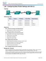
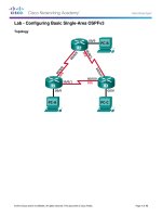
Figure 1 displays the physical connectivity within your student workgroup. You have
control over routers WGxR1 through WGxR4. You can also Telnet to other routers that are
shown in the figure, but you cannot configure them.
Physical Connectivity
© 2004 Cisco Systems, Inc. All rights reserved.
BGP v3.1—2
Figure 1: Physical Connectivity
4
The first serial interface of each of your routers is connected to the Frame Relay switch.
The first (fast) Ethernet interface of each router is connected to the LAN segment. All
routers including the shared ones (Good, Cheap, and Client) have one serial link to the
Frame Relay switch.
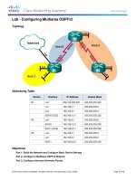
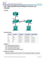
Figure 2 displays the logical connectivity of your student workgroup. Frame Relay DLCIs
are already configured on the Frame Relay switch to provide this topology.
Configuring BGP on Cisco Routers (BGP) v3.1
Copyright © 2004, Cisco Systems, Inc.
The PDF files and any printed representation for this material are the property of Cisco Systems, Inc.,
for the sole use by Cisco employees for personal study. The files or printed representations may not be
used in commercial training, and may not be distributed for purposes other than individual self-study.
Logical Connectivity
© 2004 Cisco Systems, Inc. All rights reserved.
BGP v3.1—3
Figure 2: Logical Connectivity
Exercise Procedure
Complete these steps:
Step 1
Perform initial configuration of your routers using the parameters in the following
table.
Parameter
Value
host name
Use host names as shown in Figure 2 (x is the number
of your workgroup).
Enable password
Cisco
VTY password
Cisco
WAN link encapsulation
Frame Relay
WAN link clock rate
128 kbps (configured on the Frame Relay switch)
Copyright © 2004, Cisco Systems, Inc.
The PDF files and any printed representation for this material are the property of Cisco Systems, Inc.,
for the sole use by Cisco employees for personal study. The files or printed representations may not be
used in commercial training, and may not be distributed for purposes other than individual self-study.
Lab Guide
5
Step 2
Configure two loopback addresses on each of your workgroup routers with the IP
addresses from the following table.
Router
Interface
Address
Subnet Mask
WGxR1
Loopback 0
197.x.1.1
255.255.255.0
Loopback 1
197.x.8.1
255.255.255.0
Loopback 0
197.x.2.1
255.255.255.0
Loopback 1
197.x.3.1
255.255.255.0
Loopback 0
197.x.4.1
255.255.255.0
Loopback 1
197.x.5.1
255.255.255.0
Loopback 0
197.x.6.1
255.255.255.0
Loopback 1
197.x.7.1
255.255.255.0
WGxR2
WGxR3
WGxR4
Step 3
Note
Step 4
Parameter
Value
ISP exchange point subnet
192.168.20.x, subnet mask 255.255.255.0
Client ISP subnet
192.168.21.x, subnet mask 255.255.255.0
Router “Good” has IP address 192.168.20.20, and router “Cheap” has IP address
192.168.20.22. They are shared by all workgroups. Router “Client” has IP address
192.168.21.99 and is shared by all workgroups. Frame Relay DLCIs have the same value
on both ends of the link.
Configure point-to-point Frame Relay subinterfaces on the Frame Relay links. The
IP addresses to be used on the link, as well as the DLCI values for the Frame Relay
virtual circuits, are shown in the following table.
First Router
IP Address
Second Router
IP Address
DLCI
WGxR1
192.168.x.1/30
WGxR2
192.168.x.2/30
100
WGxR2
192.168.x.5/30
WGxR3
192.168.x.6/30
101
WGxR3
192.168.x.9/30
WGxR4
192.168.x.10/30
102
Step 5
Configure IP host mappings to ease Telnet hopping between routers.
Step 6
Configure any IGP between your routers. Make sure that you do not use the IGP on
the backbone LANs.
Note
6
Configure LAN IP addresses on WGxR1 and WGxR4 using parameters from the
following table.
It is preferred that you use a classless IGP, such as OSPF, for this step.
Configuring BGP on Cisco Routers (BGP) v3.1
Copyright © 2004, Cisco Systems, Inc.
The PDF files and any printed representation for this material are the property of Cisco Systems, Inc.,
for the sole use by Cisco employees for personal study. The files or printed representations may not be
used in commercial training, and may not be distributed for purposes other than individual self-study.
Exercise Verification
You have completed this exercise when you attain these results:
All router interfaces should be active (line up, line protocol up).
You should be able to Telnet and ping between all core routers.
Copyright © 2004, Cisco Systems, Inc.
The PDF files and any printed representation for this material are the property of Cisco Systems, Inc.,
for the sole use by Cisco employees for personal study. The files or printed representations may not be
used in commercial training, and may not be distributed for purposes other than individual self-study.
Lab Guide
7
Lab Exercise 1-2: Configuring Basic BGP
Complete this lab exercise to practice what you learned in the related lesson.
Exercise Objective
In this exercise, you will configure BGP. After completing this exercise, you will be able to
meet these objectives:
Configure initial BGP setup
Configure BGP neighbors
Announce local networks in BGP
Redistribute routes into BGP
Configure basic BGP route aggregation
Monitor the status of the BGP routing process
Monitor BGP neighbors
Monitor the BGP table
Required Resources
These are the resources and equipment required to complete this exercise:
Your workgroup requires the following components:
Four Cisco 2610 routers with a WIC-1T and BGP-capable operating system software
installed.
Four CAB-X21FC + CAB-X21MT DTE-DCE serial cable combinations. The DCE side of
the cable is connected to the Cisco 3660.
Two Ethernet 10BASE-T patch cables.
IBM PC (or compatible) with Windows 95/98 and an installed Ethernet adapter.
The lab backbone requires the following components (supporting up to eight workgroups):
8
One Cisco 2610 router with a WIC-1T and BGP-capable operating system software
installed
Two Cisco 2610 routers with BGP-capable operating system software installed
One Cisco 3640 router with an installed NM-8A/S
Two Catalyst 2924M-XL Ethernet switches
Three Ethernet 10BASE-T patch cables
Configuring BGP on Cisco Routers (BGP) v3.1
Copyright © 2004, Cisco Systems, Inc.
The PDF files and any printed representation for this material are the property of Cisco Systems, Inc.,
for the sole use by Cisco employees for personal study. The files or printed representations may not be
used in commercial training, and may not be distributed for purposes other than individual self-study.
Command List
The commands used in this exercise are described in the table here.
Commands
Command
Description
router bgp as-number
Places you in BGP configuration mode
neighbor ip-address remote-as as-number
Establishes a BGP session by using your workgroup
number as the AS number
network network [mask mask]
Announces IP prefixes in BGP
ip route network mask …
Configures a static IP route
route-map name {permit | deny} seq
Defines or modifies an existing entry in a route-map
match ip address acl
Matches routes in a route-map
set origin igp
Sets the origin in a route-map
redistribute igp pid route-map name
Redistributes from your IGP into BGP
aggregate-address network mask [summaryonly]
Creates summary prefixes—use the summary-only
keyword to suppress more specific prefixes
show ip bgp summary
Verifies if the BGP session is up
show ip bgp neighbor
Enables you to view detailed information about the
neighbor
show ip bgp
Enables you to inspect the contents of the BGP table
show ip bgp network
Enables you to view detailed information about
prefixes (aggregates)
default-information originate [always]
Generates a default external route into an OSPF
routing domain—to enable advertising of the default
route regardless of whether the software has a
default route, use the option always
Copyright © 2004, Cisco Systems, Inc.
The PDF files and any printed representation for this material are the property of Cisco Systems, Inc.,
for the sole use by Cisco employees for personal study. The files or printed representations may not be
used in commercial training, and may not be distributed for purposes other than individual self-study.
Lab Guide
9
Job Aids
These job aids are available to help you complete the lab exercise:
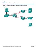
You must connect to the Internet using BGP, ensuring that all users in your network have
Internet access. You will connect to a single service provider and statically announce the
address space that the Internet Registry has assigned to you.
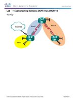
Figure 1 displays the BGP session that you will establish between WGxR1 and the “Good”
service provider.
Connecting to a Single Service Provider
© 2004 Cisco Systems, Inc. All rights reserved.
BGP v3.1—4
Figure 1: Connecting to a Single Service Provider
10
Configuring BGP on Cisco Routers (BGP) v3.1
Copyright © 2004, Cisco Systems, Inc.
The PDF files and any printed representation for this material are the property of Cisco Systems, Inc.,
for the sole use by Cisco employees for personal study. The files or printed representations may not be
used in commercial training, and may not be distributed for purposes other than individual self-study.
Task 1: Configuring BGP
In this task, you will configure your network backbone for basic BGP connectivity with a
service provider to establish BGP peering.
Exercise Procedure
Complete these steps:
Step 1
Start the BGP process on WGxR1. Use your workgroup number as the AS number.
Step 2
Configure the “Good” router to be your BGP neighbor using the following
parameters.
Parameter
Value
Service provider IP address
192.168.20.20
Service provider AS number
20
Step 3
Announce the IP prefix 197.x.0.0/16 by configuring it in the BGP routing process.
Also announce network 192.168.x.0/24.
Step 4
Ensure that WGxR1 is the exit point for your pod and is originating a default route
for your IGP.
Exercise Verification
You have completed this exercise when you attain these results:
Verify that you have established a BGP session. Remember that it may take up to a minute
to establish a BGP session. Your display should resemble the following:
WG1R1#show ip bgp summary
BGP router identifier 192.168.20.1, local AS number 1
BGP table version is 25, main routing table version 25
24 network entries and 24 paths using 3192 bytes of memory
5 BGP path attribute entries using 260 bytes of memory
4 BGP AS-PATH entries using 96 bytes of memory
1 BGP community entries using 250 bytes of memory
0 BGP route-map cache entries using 0 bytes of memory
0 BGP filter-list cache entries using 0 bytes of memory
BGP activity 24/0 prefixes, 24/0 paths, scan interval 15 secs
Neighbor
192.168.20.20
WG1R1#
V
4
AS MsgRcvd MsgSent
20
9
4
TblVer
25
InQ OutQ Up/Down State/PfxR
0
0 00:01:31
24
View detailed information about the neighbor. Your display should resemble the following:
WG1R1#show ip bgp neighbor 192.168.20.20
BGP neighbor is 192.168.20.20, remote AS 20, external link
BGP version 4, remote router ID 199.199.199.199
BGP state = Established, up for 00:19:50
Last read 00:00:50, hold time is 180, keepalive interval is 60 seconds
Neighbor capabilities:
Route refresh: advertised and received
Address family IPv4 Unicast: advertised and received
Received 27 messages, 0 notifications, 0 in queue
Sent 22 messages, 0 notifications, 0 in queue
Route refresh request: received 0, sent 0
Minimum time between advertisement runs is 30 seconds
For address family: IPv4 Unicast
Copyright © 2004, Cisco Systems, Inc.
The PDF files and any printed representation for this material are the property of Cisco Systems, Inc.,
for the sole use by Cisco employees for personal study. The files or printed representations may not be
used in commercial training, and may not be distributed for purposes other than individual self-study.
Lab Guide
11
BGP table version 25, neighbor version 25
Index 1, Offset 0, Mask 0x2
24 accepted prefixes consume 864 bytes
Prefix advertised 0, suppressed 0, withdrawn 0
Connections established 1; dropped 0
Last reset never
Connection state is ESTAB, I/O status: 1, unread input bytes: 0
Local host: 192.168.20.1, Local port: 179
Foreign host: 192.168.20.20, Foreign port: 18395
Enqueued packets for retransmit: 0, input: 0
… rest deleted …
mis-ordered: 0 (0 bytes)
Inspect the contents of the BGP table on your router. You should see a large number of
networks being advertised by the “Good” provider. Your display should resemble the
following:
WG1R1#show ip bgp
BGP table version is 32, local router ID is 192.168.20.1
Status codes: s suppressed, d damped, h history, * valid, > best, i - internal
Origin codes: i - IGP, e - EGP, ? - incomplete
Network
Next Hop
Metric LocPrf Weight Path
*> 128.20.0.0
192.168.20.20
0
0 20 i
*> 128.22.0.0
192.168.20.20
0
0 20 i
*> 128.26.0.0
192.168.20.20
0
0 20 42 26 i
*> 128.37.0.0
192.168.20.20
0
0 20 42 37 i
*> 128.42.0.0
192.168.20.20
0
0 20 42 i
*> 128.51.0.0
192.168.20.20
0
0 20 42 26 51 i
*> 128.213.0.0
192.168.20.20
0
0 20 213 i
*> 128.214.0.0
192.168.20.22
0 20 22 214 i
*> 192.20.11.0
192.168.20.20
0
0 20 i
*> 192.22.11.0
192.168.20.20
0
0 20 i
*> 192.26.11.0
192.168.20.20
0
0 20 42 26 i
*> 192.37.11.0
192.168.20.20
0
0 20 42 37 i
*> 192.42.11.0
192.168.20.20
0
0 20 42 i
*> 192.51.11.0
192.168.20.20
0
0 20 42 26 51 i
*> 192.168.1.0
0.0.0.0
0
32768 i
*> 192.168.2.0
192.168.20.2
0 20 2 i
*> 192.168.3.2/32
192.168.20.3
0 20 3 ?
Networks originating
*> 192.168.3.3/32
192.168.20.3
0 20 3 ?
in AS 3. Origin code
is “incomplete”
*> 192.168.3.4/32
192.168.20.3
0 20 3 ?
because networks are
*> 192.168.3.8/30
192.168.20.3
0 20 3 ?
redistributed.
*> 192.168.3.12/30 192.168.20.3
0 20 3 ?
*> 192.168.3.16/30 192.168.20.3
0 20 3 ?
*> 192.168.3.20/30 192.168.20.3
0 20 3 ?
*> 192.213.11.0
192.168.20.20
0
0 20 213 i
*> 192.214.11.0
192.168.20.22
0 20 22 214 i
Network
*> 197.1.0.0/16
0.0.0.0
0
32768 i
originating
*> 197.2.0.0/16
192.168.20.2
0 20 2 i
in AS 2.
WG1R1#
Telnet from WGxR1 into the router “Good” and verify that it is receiving your networks
over BGP.
Verify that you are receiving networks that are announced by other customers.
*> 192.168.1.0
*> 197.1.0.0/16
12
192.168.20.1
192.168.20.1
0
0
0 1 i
0 1 I
Perform ping and trace from WGxR4 to 192.20.11.1 (an Internet destination that is
announced by router “Good”).
Configuring BGP on Cisco Routers (BGP) v3.1
Copyright © 2004, Cisco Systems, Inc.
The PDF files and any printed representation for this material are the property of Cisco Systems, Inc.,
for the sole use by Cisco employees for personal study. The files or printed representations may not be
used in commercial training, and may not be distributed for purposes other than individual self-study.
Answer these questions:
Q1)
What do you need in order to propagate classful networks?
Q2)
What do you need in order to propagate classless networks (supernets or subnets)?
Q3)
Why do some networks that are received from router “Good” have a next-hop address
pointing to other routers?
Q4)
What command would you use to see if a neighbor is sending you any updates and how
many?
Task 2: Configuring Route Redistribution in BGP
Your network has grown, and you can no longer rely on manually configuring your address
space in the BGP process. In this task, you will use redistribution to announce a large number
of networks into the BGP routing process. You will also use route-maps to set the origin of
BGP routes to “IGP” instead of “incomplete.”
In this task, you will remove all networks from your BGP definitions (from Task 1) and
announce them by using redistribution from your IGP into BGP with a route-map, which sets
the origin code to “IGP.” Make sure that you do not announce 192.168.20.0/24 and
192.168.21.0/24 networks into BGP.
Exercise Procedure
Complete these steps:
Step 1
Remove all BGP network statements from the previous exercise.
Step 2
Telnet to router “Good” and verify that it no longer receives your networks.
Step 3
Configure an access-list that permits all your networks except those that are shared
among workgroups.
Step 4
Configure a route-map. Use the new access-list with a match command in the routemap. Use the set command in the route-map to set the origin to “IGP.”
Note
Step 5
Route-maps will be covered in detail in the module “Route Selection Using Policy Controls.”
Configure redistribution from your IGP into BGP by using the previously configured
route-map.
Copyright © 2004, Cisco Systems, Inc.
The PDF files and any printed representation for this material are the property of Cisco Systems, Inc.,
for the sole use by Cisco employees for personal study. The files or printed representations may not be
used in commercial training, and may not be distributed for purposes other than individual self-study.
Lab Guide
13
Exercise Verification
You have completed this exercise when you attain these results:
Log into the service provider router (“Good”) and verify that it receives proper networks
from you. Your display should resemble the following:
Good>show ip bgp
BGP table version is 70, local router ID is 199.199.199.199
Status codes: s suppressed, d damped, h history, * valid, > best, i - internal
Origin codes: i - IGP, e - EGP, ? - incomplete
Individual subnets
are seen if
“no auto-summary”
command is used in
BGP.
Network
. . .
*> 192.168.1.0/30
*> 192.168.1.0
*> 192.168.1.4/30
*> 192.168.1.8/30
*> 197.1.1.0
*> 197.1.2.0
*> 197.1.3.0
*> 197.1.4.0
*> 197.1.5.0
*> 197.1.6.0
*> 197.1.7.0
*> 197.1.8.0
. . .
Good>
Next Hop
192.168.20.1
192.168.20.1
192.168.20.1
192.168.20.1
192.168.20.1
192.168.20.1
192.168.20.1
192.168.20.1
192.168.20.1
192.168.20.1
192.168.20.1
192.168.20.1
Metric LocPrf Weight Path
0
0
2681856
3193856
0
2297856
2297856
2809856
2809856
3321856
3321856
0
0
0
0
0
0
0
0
0
0
0
0
0
1
1
1
1
1
1
1
1
1
1
1
1
i
i
i
i
i
i
i
i
i
i
i
i
Make sure that you are not originating networks 192.168.20.0/24 and 192.168.21.0/24.
Verify that your networks are removed from the BGP table when they become unavailable
(try shutting down one of the loopback interfaces).
Answer these questions:
14
Q1)
What is the major difference between this implementation and the previous one?
Which is better and why?
Q2)
What precautions do you have to take when using redistribution?
Configuring BGP on Cisco Routers (BGP) v3.1
Copyright © 2004, Cisco Systems, Inc.
The PDF files and any printed representation for this material are the property of Cisco Systems, Inc.,
for the sole use by Cisco employees for personal study. The files or printed representations may not be
used in commercial training, and may not be distributed for purposes other than individual self-study.
Task 3: Configuring BGP Aggregation
Your ISP has requested that you provide only summarized prefixes for your address range
197.x.0.0. However, because of diagnostic needs, you still need to announce the network
197.x.8.0.
In this task, you will configure BGP aggregation as requested, using the aggregate-address
command.
Exercise Procedure
Complete these steps:
Step 1
>
>
>
>
>
>
>
>
Log into the router “Good”; verify that the ISP sees all your individual loopback
networks.
197.1.1.0
197.1.2.0
197.1.3.0
197.1.4.0
197.1.5.0
197.1.6.0
197.1.7.0
197.1.8.0
Step 2
Note
192.168.20.1
192.168.20.1
192.168.20.1
192.168.20.1
192.168.20.1
192.168.20.1
192.168.20.1
192.168.20.1
0
0
0
0
0
0
0
0
0
0
0
0
0
0
0
0
1
1
1
1
1
1
1
1
i
i
i
i
i
i
i
i
Use the aggregate command in your BGP process to aggregate the 197.x.0.0
network as requested by your ISP.
Use the keyword summary-only if you do not want to announce individual prefixes.
Exercise Verification
You have completed this exercise when you attain these results:
Check the BGP table on your router WGxR1 to verify the correct routing information is
present.
Log into the service provider (“Good”) router and check its BGP table. Suppressed
networks should not be visible on router “Good.”
View detailed information about one of the aggregates.
Answer these questions:
Q1)
Do you see all your prefixes on the provider router? Why?
Q2)
What do you need to be able to generate and propagate aggregate routes?
Copyright © 2004, Cisco Systems, Inc.
The PDF files and any printed representation for this material are the property of Cisco Systems, Inc.,
for the sole use by Cisco employees for personal study. The files or printed representations may not be
used in commercial training, and may not be distributed for purposes other than individual self-study.
Lab Guide
15
Lab Exercise 2-1: Configuring a Transit AS
Complete this lab exercise to practice what you learned in the related lesson.
Exercise Objective
In this exercise, you will enable a service provider network with multiple BGP connections to
other autonomous systems to behave as a transit AS. After completing this exercise, you will be
able to meet these objectives:
Plan the migration of an existing backbone toward a fully meshed IBGP backbone that is
designed for transit traffic
Configure IBGP sessions between loopback interfaces
Configure BGP synchronization to ensure successful IBGP operation of the transit AS
Monitor IBGP operation
Required Resources
These are the resources and equipment required to complete this exercise:
Your workgroup requires the following components:
Four Cisco 2610 routers with a WIC-1T and BGP-capable operating system software
installed.
Four CAB-X21FC + CAB-X21MT DTE-DCE serial cable combinations. The DCE side of
the cable is connected to the Cisco 3660.
Two Ethernet 10BASE-T patch cables.
IBM PC (or compatible) with Windows 95/98 and an installed Ethernet adapter.
The lab backbone requires the following components (supporting up to eight workgroups):
16
One Cisco 2610 router with a WIC-1T and BGP-capable operating system software
installed
Two Cisco 2610 routers with BGP-capable operating system software installed
One Cisco 3640 router with an installed NM-8A/S
Two Catalyst 2924M-XL Ethernet switches
Three Ethernet 10BASE-T patch cables
Configuring BGP on Cisco Routers (BGP) v3.1
Copyright © 2004, Cisco Systems, Inc.
The PDF files and any printed representation for this material are the property of Cisco Systems, Inc.,
for the sole use by Cisco employees for personal study. The files or printed representations may not be
used in commercial training, and may not be distributed for purposes other than individual self-study.
Command List
The commands used in this exercise are described in the table here.
Commands
Command
Description
router bgp as-number
Places you in BGP configuration mode
neighbor ip-address remote-as as-number
Establishes an IBGP session by using your workgroup
number as the AS number
neighbor ip-address update-source interface
Uses the IP address of the specified interface as the
source address for the BGP session
show ip bgp
Enables you to inspect the contents of the BGP table
show ip bgp regexp regexp
Enables you to use a regular expression to filter the
output of the show ip bgp command
neighbor ip-address next-hop-self
Configures the router as the next hop for a BGPspeaking neighbor
no synchronization
Disables synchronization of IGP and BGP routes
Copyright © 2004, Cisco Systems, Inc.
The PDF files and any printed representation for this material are the property of Cisco Systems, Inc.,
for the sole use by Cisco employees for personal study. The files or printed representations may not be
used in commercial training, and may not be distributed for purposes other than individual self-study.
Lab Guide
17
Job Aids
These job aids are available to help you complete the lab exercise:
With the rapid growth of the Internet, you decide to become an Internet service provider
(ISP), and you already have your first customer.
In this exercise, you will transform your network into a transit AS that runs BGP on all core
routers.
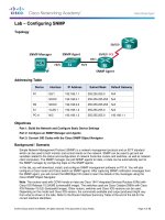
Configure a full mesh of IBGP sessions between all routers in your AS. Establish these
BGP sessions between Loopback 0 interfaces.
Figure 1 displays the required BGP connectivity within your AS as well as the BGP
sessions with your customer and your upstream ISPs.
Creating a Full Mesh of IBGP Sessions
© 2004 Cisco Systems, Inc. All rights reserved.
BGP v3.1—5
Figure 1: Creating a Full Mesh of IBGP Sessions
18
Configuring BGP on Cisco Routers (BGP) v3.1
Copyright © 2004, Cisco Systems, Inc.
The PDF files and any printed representation for this material are the property of Cisco Systems, Inc.,
for the sole use by Cisco employees for personal study. The files or printed representations may not be
used in commercial training, and may not be distributed for purposes other than individual self-study.
Task 1: Configuring the BGP Transit AS
In this task, you will configure your network backbone as a fully meshed IBGP backbone
acting as a transit AS.
Exercise Procedure
Complete these steps:
Step 1
Clean up your BGP configuration by removing the BGP process and the default
route from the IGP on WGxR1. You may also remove the access-list and route-map.
Step 2
Start the BGP process on all routers in your workgroup.
Step 3
Advertise your prefixes (197.x.0.0/16 and 192.168.x.0/24) in BGP on routers
WGxR1 and WGxR4.
Step 4
Re-establish the neighbor relationships to router “Good” without any filters on
router WGxR1. Use the parameters from the following table.
Step 5
Router
AS Number
IP Address
Good
20
192.168.20.20
Establish a BGP session with router “Client” on router WGxR4. Use the parameters
from the following table.
Parameter
Value
Client IP address
192.168.21.99
Client AS number
99
Step 6
Configure all routers in your workgroup as IBGP neighbors (IBGP full mesh). Use
loopback interfaces to establish these IBGP sessions.
Step 7
Ensure EBGP reachability by all IBGP-speaking routers within your transit AS
without redistributing the connected interfaces of either external Ethernet.
Exercise Verification
You have completed this exercise when you attain these results:
Check BGP on all core routers and the router “Client” and ensure that they have established
the correct sessions with their peers. Your display should resemble the following:
WG1R1#show ip bgp summary
…
Neighbor
V
AS MsgRcvd MsgSent
192.168.20.20
4
20
1189
1200
192.168.20.22
4
22
1195
1183
197.1.2.1
4
1
1174
1196
197.1.4.1
4
1
1170
1188
197.1.6.1
4
1
1171
1183
TblVer
52
52
52
52
52
InQ OutQ Up/Down State/PfxRcd
0
0 13:34:45
23
0
0 13:34:46
23
0
0 13:34:58
0
0
0 13:35:17
0
0
0 13:34:58
13
WG1R2#show ip bgp summary
…
Neighbor
V
AS MsgRcvd MsgSent
197.1.1.1
4
1
1200
1179
197.1.4.1
4
1
1173
1173
197.1.6.1
4
1
1176
1170
TblVer
125
125
125
InQ OutQ Up/Down State/PfxRcd
0
0 13:38:09
24
0
0 13:38:31
0
0
0 13:37:58
13
Copyright © 2004, Cisco Systems, Inc.
The PDF files and any printed representation for this material are the property of Cisco Systems, Inc.,
for the sole use by Cisco employees for personal study. The files or printed representations may not be
used in commercial training, and may not be distributed for purposes other than individual self-study.
Lab Guide
19
WG1R3#show ip bgp summary
…
Neighbor
V
AS MsgRcvd MsgSent
197.1.1.1
4
1
1193
1175
197.1.2.1
4
1
1175
1175
197.1.6.1
4
1
1183
1175
TblVer
78
78
78
InQ OutQ Up/Down State/PfxRcd
0
0 13:40:33
24
0
0 13:40:37
0
0
0 13:40:04
13
WG1R4#show ip bgp summary
…
Neighbor
V
AS MsgRcvd MsgSent
192.168.21.99
4
99
1191
1192
197.1.1.1
4
1
1190
1178
197.1.2.1
4
1
1173
1179
197.1.4.1
4
1
1175
1183
TblVer
14
14
14
14
InQ OutQ Up/Down State/PfxRcd
0
0 13:40:38
11
0
0 13:41:04
24
0
0 13:40:54
0
0
0 13:40:54
0
Client#show ip bgp summary
…
Neighbor
V
AS MsgRcvd MsgSent
192.168.21.X
4
1
1147
1146
TblVer
18
InQ OutQ Up/Down State/PfxRcd
0
0 13:42:01
2
Check the BGP table on router “Client” and verify that it is correctly receiving BGP routes.
Your display should resemble the following:
Client#show ip bgp
BGP table version is 119, local router ID is 197.99.111.1
Status codes: s suppressed, d damped, h history, * valid, > best, i - internal
Origin codes: i - IGP, e - EGP, ? - incomplete
Network
10.0.0.0
99.0.0.0
128.20.12.0/24
128.37.0.0
128.42.0.0
128.213.0.0
192.20.12.0/30
192.37.11.0
192.42.11.0
192.168.1.0
192.213.11.0
197.1.0.0/16
197.99.1.0
197.99.11.0
197.99.12.0
197.99.13.0
197.99.20.0
197.99.22.0
197.99.80.0
197.99.111.1/32
197.99.120.0
197.99.128.0/20
200.20.0.0/16
*>
*>
*>
*>
*>
*>
*>
*>
*>
*>
*>
*>
*>
*>
*>
*>
*>
*>
*>
*>
*>
*>
*>
Next Hop
192.168.21.1
0.0.0.0
192.168.21.1
192.168.21.1
192.168.21.1
192.168.21.1
192.168.21.1
192.168.21.1
192.168.21.1
192.168.21.1
192.168.21.1
192.168.21.1
0.0.0.0
0.0.0.0
0.0.0.0
0.0.0.0
0.0.0.0
0.0.0.0
0.0.0.0
0.0.0.0
0.0.0.0
0.0.0.0
192.168.21.1
Metric LocPrf Weight
0
0
32768
0
0
0
0
0
0
0
0
0
0
0
0
0
32768
0
32768
0
32768
0
32768
0
32768
0
32768
0
32768
0
32768
0
32768
0
32768
0
Path
1 20
i
1 20
1 20
1 20
1 20
1 20
1 20
1 20
1 i
1 20
1 i
i
i
i
i
i
i
i
i
i
i
1 20
i
i
42 37 i
42 i
213 i
i
42 37 i
42 i
213 i
i
Use traceroute from router WGxR1 to the loopback interface on router “Client”
(197.99.1.1). You should see a path similar to the one here:
WG1R1# traceroute 197.99.1.1
Type escape sequence to abort.
Tracing the route to 197.99.1.1
1
2
3
4
20
192.168.1.2 16 msec 16 msec 17 msec
192.168.1.6 32 msec 32 msec 28 msec
192.168.1.10 44 msec 40 msec 40 msec
192.168.21.99 48 msec * 44 msec
Configuring BGP on Cisco Routers (BGP) v3.1
Copyright © 2004, Cisco Systems, Inc.
The PDF files and any printed representation for this material are the property of Cisco Systems, Inc.,
for the sole use by Cisco employees for personal study. The files or printed representations may not be
used in commercial training, and may not be distributed for purposes other than individual self-study.
Answer these questions:
Q1)
Check the BGP table on router “Client.” How many prefixes coming from your AS are
in that BGP table? ____________
Q2)
Is there any other way of discovering how many prefixes that you have advertised to
the router “Client”?
Q3)
Why did you have to disable synchronization?
Q4)
Why did you have to establish a full mesh of IBGP sessions?
Copyright © 2004, Cisco Systems, Inc.
The PDF files and any printed representation for this material are the property of Cisco Systems, Inc.,
for the sole use by Cisco employees for personal study. The files or printed representations may not be
used in commercial training, and may not be distributed for purposes other than individual self-study.
Lab Guide
21
Lab Exercise 3-1: Using Multihomed BGP
Networks
Complete this lab exercise to practice what you learned in the related lesson.
Exercise Objective
In this exercise, you will configure BGP as part of a customer scenario where you must support
connections to multiple ISPs. After completing this exercise, you will be able to meet these
objectives:
Configure BGP neighbors to support a multihomed customer scenario
Monitor the status of the BGP routing process
Monitor BGP neighbors in a multihomed customer scenario
Required Resources
These are the resources and equipment required to complete this exercise:
Your workgroup requires the following components:
Four Cisco 2610 routers with a WIC-1T and BGP-capable operating system software
installed.
Four CAB-X21FC + CAB-X21MT DTE-DCE serial cable combinations. The DCE side of
the cable is connected to the Cisco 3660.
Two Ethernet 10BASE-T patch cables.
IBM PC (or compatible) with Windows 95/98 and an installed Ethernet adapter.
The lab backbone requires the following components (supporting up to eight workgroups):
22
One Cisco 2610 router with a WIC-1T and BGP-capable operating system software
installed
Two Cisco 2610 routers with BGP-capable operating system software installed
One Cisco 3640 router with an installed NM-8A/S
Two Catalyst 2924M-XL Ethernet switches
Three Ethernet 10BASE-T patch cables
Configuring BGP on Cisco Routers (BGP) v3.1
Copyright © 2004, Cisco Systems, Inc.
The PDF files and any printed representation for this material are the property of Cisco Systems, Inc.,
for the sole use by Cisco employees for personal study. The files or printed representations may not be
used in commercial training, and may not be distributed for purposes other than individual self-study.
Command List
The commands used in this exercise are described in the table here.
Commands
Command
Description
router bgp as-number
Places you in BGP configuration mode
neighbor ip-address remote-as as
Starts a BGP session with the neighboring AS
neighbor ip-address weight weight
Assigns a weight to all updates that are received
from the specified neighbor
show ip bgp summary
Verifies the state of BGP sessions
show ip bgp
Enables you to inspect the contents of the BGP
table
Job Aids
These job aids are available to help you complete the lab exercise:
You have started to provide mission-critical e-commerce services, and you must ensure
their high availability. You decide to connect to a new ISP, “Cheap,” using “Cheap” as
your primary ISP and “Good” as your backup ISP.
Figure 1 shows the connectivity that you need to establish for the second BGP session with
the new provider router (“Cheap”).
Connecting to Two Different
Service Providers
© 2004 Cisco Systems, Inc. All rights reserved.
BGP v3.1—6
Figure 1: Connecting to Two Different Service Providers
Copyright © 2004, Cisco Systems, Inc.
The PDF files and any printed representation for this material are the property of Cisco Systems, Inc.,
for the sole use by Cisco employees for personal study. The files or printed representations may not be
used in commercial training, and may not be distributed for purposes other than individual self-study.
Lab Guide
23