HVAC Systems Design Handbook part 10
Bạn đang xem bản rút gọn của tài liệu. Xem và tải ngay bản đầy đủ của tài liệu tại đây (382.17 KB, 46 trang )
321
Chapter
10
Equipment: Part 2
Heating
10.1 Introduction
Heating is the first word in the acronym HVAC. It is the most impor-
tant part because without heating mankind would have difficulty in
surviving. Proper design of the heating system is even more critical
than that of ventilation or cooling. Human history began to develop
with the discovery and control of fire which increased people’s ability
to survive in a harsh environment. In modern heating system design,
two primary concerns are proper system sizing, to achieve comfort,
and system reliability. Capital cost, operating cost, and pollution con-
trol are secondary in consideration. Pollution control is addressed by
code authorities. Energy conservation and operating costs go together
and have a considerable effect on life-cycle costs.
These concerns and many others are addressed in this chapter.
10.2 General
In a modern heating system, heating can be provided by
1. Fuel-fired or electric boilers that produce steam, hot water, or ther-
mal liquids for direct or indirect use
2. Furnaces, unit heaters, duct heaters, and outside-air heaters which
provide hot air for direct circulation to the conditioned space
3. Waste heat furnaces and boilers which utilize the waste energy
from some other source, such as a process, an incinerator, or re-
frigeration equipment
Source: HVAC Systems Design Handbook
Downloaded from Digital Engineering Library @ McGraw-Hill (www.digitalengineeringlibrary.com)
Copyright © 2004 The McGraw-Hill Companies. All rights reserved.
Any use is subject to the Terms of Use as given at the website.
322 Chapter Ten
4. Solar energy collectors, both passive and active, which heat either
water or air and, in some cases, solid materials
5. Heat pumps, either liquid or air
6. Direct-fired radiant heaters, either electric or natural gas
7. Geothermal sources
End users are provided heat by
1. Direct air—furnaces, duct heaters, outside-air heaters, reheat
units, ducted heat pumps
2. Indirect air—coils and air-handling units, fan-coil units, unit ven-
tilators
3. Liquid—radiators, convectors, liquid-filled radiant heaters
4. Radiation—direct radiation from panels, floors, or other radiators
10.3 Boiler Applications
Boilers can produce low-, medium-, or high-temperature water; low-,
medium-, or high-pressure steam (including process steam); and ther-
mal liquid. Break points between categories are usually defined by
codes.
10.3.1 Hot water boilers
Low-temperature water boilers (to 250ЊF) are the most widely used
type for residential, apartment, and commercial construction. Me-
dium-temperature water boilers (250 to 310ЊF) are generally used in
industrial and campus-type facilities. High-temperature water (310 to
450ЊF) is used for extended campus-type facilities and industrial pro-
cess facilities. Thermal liquid heaters are primarily found in industrial
applications where both space heating and process heating are signif-
icant loads.
10.3.2 Steam boilers
Low-pressure boilers (up to 15 lb/in
2
gauge) are generally found in
commercial, apartment house, and single-unit industrial facilities.
They are used for space heating and domestic hot water, through end-
use heat exchangers. Medium-pressure steam applications (15 to 150
lb/in
2
gauge) are generally found in campus-type facilities, hospitals,
and industrial plants where there are significant process require-
ments. Power generation high-pressure steam boilers operate in the
range of 150 to 900 lb/in
2
gauge or more with some degree of super-
Equipment: Part 2
Downloaded from Digital Engineering Library @ McGraw-Hill (www.digitalengineeringlibrary.com)
Copyright © 2004 The McGraw-Hill Companies. All rights reserved.
Any use is subject to the Terms of Use as given at the website.
Equipment: Part 2 323
heat in order to obtain good turbine efficiency. Waste heat from tur-
bines is often used for space heating, domestic hot water, and process
requirements. Steam at high pressure can be used to provide lower
pressure steam, either by direct pressure reduction or by indirect gen-
eration through a heat exchanger. The latter is useful if high quality
steam is required.
10.4 Boiler Types
Boilers can be categorized in many different ways. For this book, the
following categories are used.
10.4.1 Cast-iron sectional boilers
Cast-iron sectional boilers can produce hot water or steam at pres-
sures up to 15 lb/in
2
gauge for steam and 30 lb/in
2
gauge for water.
They are either atmospheric or power burner gas-fired, and they come
in individual heat transfer sections which are modularized to obtain
a range of capacities. The small sections allow for installation in
spaces which are inaccessible to package boilers. They are easy to
maintain and have the longest physical life of any type of boiler. Care
must be taken to avoid the problem of thermal (cold) shock of these
boilers for they fail if the castings crack.
10.4.2 Fire tube boilers
In fire tube boilers, the products of combustion are confined within a
series of tubes surrounded by water. The most popular type is the
Scotch marine boiler in which the combustion furnace is in the shape
of a cylinder surrounded by water. Other types have steel firebox fur-
naces, brick-set firebox furnaces, and in some cases a combination of
both. Capacities go up to about 1000 boiler horsepower (bhp) (1 bhp
Ӎ 33,480 Btu/h). Their popularity is due to their low first cost. Their
useful life is less than that of either cast-iron or water tube boilers,
and some fire-tube designs are susceptible to thermal shock under
wide temperature differentials and sudden load shifts. The maximum
operating pressure is usually 250 lb /in
2
gauge or less. Many older
boilers had atmospheric-type burners. Current practice favors forced-
draft burners. The Scotch marine boilers are all forced-draft design.
10.4.3 Water tube boilers
In water tube boilers, the water is inside the boiler tubes and the
products of combustion surround the tubes. There is a wide variety of
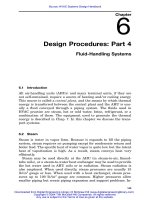
configurations, including slant-tube (Fig. 10.1), bent-tube (D-type),
Equipment: Part 2
Downloaded from Digital Engineering Library @ McGraw-Hill (www.digitalengineeringlibrary.com)
Copyright © 2004 The McGraw-Hill Companies. All rights reserved.
Any use is subject to the Terms of Use as given at the website.
324 Chapter Ten
Figure 10.1
Slant-tube water tube boiler.
O-type, C-type, and express type. They range in size from small resi-
dential units to large utility boilers. They have an extended service
life if proper water treatment and maintenance are provided. Water
tube boilers may be factory-assembled and tested, package type, or
field-assembled; the field-assembled boiler is more common in sizes
above 200,000 lb/h capacity. Operating pressures of 150 to 900 lb/in
2
gauge or greater are used where process requirements are severe or
where power generation is a consideration.
10.4.4 Thermal liquid boilers
Thermal liquid boilers are of the water tube type, but instead of water,
a special thermal liquid is used. This liquid permits the generation of
high temperatures—600 to 800ЊF—at low pressures. These units are
often found in manufacturing facilities, with the thermal liquid used
in processes. Steam is generated through a heat exchanger for use in
space heating and other purposes. These boilers are prevalent in Eu-
rope but have seen limited application in the United States. Thermal
liquids are often elusive in containment. Special consideration must
be given to joint systems and device seals.
Equipment: Part 2
Downloaded from Digital Engineering Library @ McGraw-Hill (www.digitalengineeringlibrary.com)
Copyright © 2004 The McGraw-Hill Companies. All rights reserved.
Any use is subject to the Terms of Use as given at the website.
Equipment: Part 2 325
10.4.5 Steam quality
Heating and domestic hot water applications utilize saturated steam.
Saturated steam is at a temperature and pressure that correspond to
the saturation conditions discussed in Sec. 6.2 and is said to have 100
percent quality. Steam with some free moisture present has less than
100 percent quality (down to zero quality for condensed water). ‘‘Su-
perheated’’ means that additional heat is applied to the steam to drive
its temperature above the saturation temperature at the existing pres-
sure. In the boiler, this is accomplished in a special tube bank called
a superheater. Superheat is required for many turbine and process
applications, including cogeneration, but this steam must be ‘‘desu-
perheated’’ for use in normal heating and domestic water applications.
10.5 Combustion Processes and Fuels
The primary source of energy in a heating boiler is the combustion of
a fossil fuel—coal, oil, or gas—or waste materials. The use of peat,
garbage, sawdust, petroleum coke, and other waste products is in-
creasing, but it is still a small fraction of the total fuel burned in this
country.
Combustion is a process of burning—combining the fuel with oxygen
and igniting the mixture. The result is heat release, absorbed through
radiation, convection, and, to some degree, conduction.
10.5.1 The combustion process
The combustion process follows basic principles called the three T’s of
combustion. The first one is time—the time required for the air to
properly mix with the fuel and for the combustion process to be com-
pleted. It is critical when waste materials are being combusted in con-
junction with standard fuels. The second is temperature—the temper-
ature at which the fuel will ignite, oxidation is accelerated, and the
process of combustion begins. Ignition temperatures are well estab-
lished for standard fossil fuels but must be carefully considered when
waste or other organic-type materials are being burned. The third is
turbulence—the process of thoroughly mixing the air and fuel so that
each particle of fuel is in contact with the right amount of oxygen and
combustion can continue to completion. The turbulence must be vio-
lent enough to ensure good contact between the fuel and the oxygen.
Assuming there is enough combustion air to work with, inadequate
turbulence is the most common cause of incomplete combustion. In-
adequate turbulence can result in the generation of excessive amounts
Equipment: Part 2
Downloaded from Digital Engineering Library @ McGraw-Hill (www.digitalengineeringlibrary.com)
Copyright © 2004 The McGraw-Hill Companies. All rights reserved.
Any use is subject to the Terms of Use as given at the website.
326 Chapter Ten
of carbon monoxide, and combustion may continue well beyond the
furnace portion of the boiler.
10.5.2 The chemical reaction
In its simplest form, the combustion of natural gas (methane, CH
4
)
with air as a source of oxygen, the chemical reaction can be written
CH ϩ 2(4N ϩ O)⇒ CO ϩ 2H O ϩ 8N ϩ heat
422222
This describes a perfect and complete or stoichiometric combustion
process. In practice, the process is never perfect or complete. Some
carbon monoxide is formed, and some contaminants, such as sulfur,
are present and enter into the process. Sulfuric and nitric acids and
nitrous oxides are often formed, along with other undesirable com-
pounds.
10.5.3 Excess air
Because the combustion process is never perfect and perfect mixing of
air and fuel is never achieved, every combustion process requires ex-
cess air. Excess air is the additional air that must be added to the
theoretically perfect mixture to ensure as complete a combustion pro-
cess as is practically possible. The larger the amount of excess air, the
lower the combustion efficiency. Often overlooked is the possibility of
condensation in the boiler or flue that has too much excess air. It can
be reasoned that turbulence is a most important factor in the com-
bustion process. Almost all of the newest boiler developments have
been in burner design, in an attempt to improve the mixing of air and
fuel to minimize excess air, to maximize combustion efficiency, and to
minimize the generation of nitrous oxides.
10.5.4 Combustion efficiency
The combustion efficiency is the ratio of fuel heat input minus the
stack loss (through the chimney or vent), divided by the fuel heat
input. Typical efficiencies for mechanically fired boilers range from 75
to 83 percent for new installations at full-load conditions. Firing at
reduced capacity may reduce the combustion efficiency. Therefore it is
desirable to match the boiler to the load as closely as possible or to
use multiple boilers.
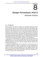
The overall thermal efficiency is the gross output in Btu/h divided
by the fuel heat input in Btu/ h. This rating takes into account the
noncombustion losses from the boiler, such as radiation (see Fig. 10.2).
Equipment: Part 2
Downloaded from Digital Engineering Library @ McGraw-Hill (www.digitalengineeringlibrary.com)
Copyright © 2004 The McGraw-Hill Companies. All rights reserved.
Any use is subject to the Terms of Use as given at the website.
Equipment: Part 2 327
Figure 10.2
Boiler or furnace thermal input and output.
The seasonal thermal efficiency is the ratio of net delivered useful
heat to gross fuel input and accommodates all system losses. Seasonal
efficiencies for systems may range from 40 to 80 percent.
10.5.5 Fuels
Gaseous fuels include natural gas, manufactured gas, and liquefied
petroleum gases (propane and butane).
Oil fuels include distillates or lightweight oils, especially no. 2, and
residuals or heavy oils, nos. 4, 5, and 6. The residual oils have high
viscosities and require preheating before they can be pumped and at-
omized. They are used only where proper handling and preheating can
be provided, mostly in large boiler plants.
Solid fuels include bituminous and anthracite coals, coke, peat, and
sawdust. A most critical factor in their utilization is the ash fusion
temperature. Liquefied sodium compounds in the hot ash deposits may
cool and scale up the convection banks of the boiler. Clinkers are an
example of fused ash compounds.
Electricity can also be considered a fuel, and it is sometimes used
to fire small steam and water boilers.
Waste materials are being used more and more in boilers, either in
combination with gas, oil, or coal or as the primary fuel source. Many
of these solid waste materials contain large amounts of impurities,
such as chlorides, which can cause serious damage to boiler heat
transfer surfaces. Under no circumstances should the utilization of
Equipment: Part 2
Downloaded from Digital Engineering Library @ McGraw-Hill (www.digitalengineeringlibrary.com)
Copyright © 2004 The McGraw-Hill Companies. All rights reserved.
Any use is subject to the Terms of Use as given at the website.
328 Chapter Ten
solid waste be undertaken without the assistance of either the equip-
ment manufacturer or a competent consultant, or both.
Wood became very popular for a time and has been in use for many
years. A major problem with wood is its moisture content and resinous
deposits. Supplies have become limited in many areas.
10.6 Fuel-Burning Equipment
Burners are devices for controlling the combustion process by mixing
the fuel and air in the proper relationship and making the process
efficient.
10.6.1 Coal burners
Coal, as a fuel for small-scale applications, has become less common
over time. While coal as a fuel is relatively inexpensive, the mecha-
nisms for fuel transport and firing and ash handling drive the overall
owning and operating cost above that for natural gas. Pollution con-
straints are also costly. In spite of this, there is still a demand for the
use of coal in some instances, particularly in large-scale facilities.
Coal and other solid fuels are fired automatically by means of stok-
ers, pulverizers, or fluid-bed combustion systems. A stoker is a means
of adding fuel on a metered basis to an existing fire. An underfeed
stoker, normally applied to small boilers and furnaces, feeds fresh fuel
from below the fire. The fuel is spread out on dump grates for the
completion of combustion. A traveling-grate stoker has a moving or
vibrating grate on which the fuel is deposited. The fuel burns as the
grate moves so that at the end of the grate the ash is dumped to an
ash pit from which it may be removed manually or mechanically. A
spreader stoker feeds a traveling grate, or a dump grate, but the coal
is deposited by throwing it onto the grate with a special feed device.
A vibrating stoker is sloped so that the fuel moves down the grate by
gravity from the feed end as lateral rods are moved back and forth.
All these stokers include forced-draft and /or induced-draft fans to con-
trol the flow of combustion air. The balance between overfire air and
underfire air is critical for complete combustion and reduction of par-
ticulate emissions.
Pulverized coal firing is found in larger (150 million Btu /h) boilers.
Raw coal is fed through a mill which pulverizes the coal into coffee-
ground to dust-size particles which are then introduced into the fire-
box through a burner tube similar to a gas burner. There is a violent
mixing of coal particles and air to effect combustion.
An alternative concept for solid fuel and solid waste firing is the
atmospheric fluidized-bed combustion system. Although it has been
Equipment: Part 2
Downloaded from Digital Engineering Library @ McGraw-Hill (www.digitalengineeringlibrary.com)
Copyright © 2004 The McGraw-Hill Companies. All rights reserved.
Any use is subject to the Terms of Use as given at the website.
Equipment: Part 2 329
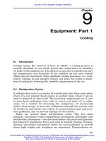
Figure 10.3
Atmospheric gas burner.
used for many years in the sewage sludge combustion business, its
application to power and heating boilers is relatively new. The solid
fuel or waste is ground or crushed to a uniform size and then injected
into a combustion bed, usually sand. Air is blown through beneath the
bed, fluidizing the fuel and suspending it above the bed, where pri-
mary combustion takes place. Limestone or some similar material is
mixed with or injected into the fuel, where it absorbs sulfur, thereby
reducing the emission of sulfur compounds. A fabric filter (baghouse)
is required to remove particulates from the process. These systems
require a properly trained and experienced operating staff. The ad-
vantage of the system is the reduced emission of sulfur and nitrogen
compounds.
10.6.2 Natural and Liquefied Petroleum
(LP) gas burners
Gas burners are of the atmospheric, fan-assisted, or premixed type.
The atmospheric burner (Fig. 10.3) is found in many residential ap-
plications and in commercial and industrial cast-iron boilers. It is also
used in most direct-fired unit heaters. It depends on the inlet gas pres-
sure and stack effect to provide combustion air and mixing. Primary
combustion air is entrained by induction and mixes with the gas; the
geometry of the burner is designed to provide an optimal fuel-air mix-
ture. Secondary air is entrained over the fire to provide more complete
combustion.
Forced-draft, fan-assisted or power burners use a fan to provide the
combustion air, with a significant improvement in air-fuel mixing and
efficiency compared with the atmospheric burner. Power burners are
in wide use today in most heating boilers.
Premix burners mix the fuel and air in an internal mixing chamber
so that optimum excess-air relationships are achieved. This burner
has a very short, intense flame and is primarily found in applications
where size or very high temperatures are significant.
Equipment: Part 2
Downloaded from Digital Engineering Library @ McGraw-Hill (www.digitalengineeringlibrary.com)
Copyright © 2004 The McGraw-Hill Companies. All rights reserved.
Any use is subject to the Terms of Use as given at the website.
330 Chapter Ten
10.6.3 Oil burners
Atmospheric-type oil burners and rotary-cup burners were used in the
past. Present-day burners are of the mechanical atomizing type that
use an oil pump to develop an atomized oil spray through a nozzle. A
fan provides air which is introduced in a swirling pattern at the nozzle
to provide good mixing.
Oil burners in larger boilers may use a separate atomizing agent,
such as compressed air or steam, for improving atomization This sig-
nificantly improves the combustion process, but there is a cost penalty
for the power used. In large boilers, the combustion improvement and
control of the flame pattern are more important than the additional
power cost.
About 30 years ago a new oil burner, the low-excess-air or sleeve-
type burner, came to the market. It provides good combustion with as
low as 2 or 3 percent excess air, compared with 15 percent or more for
standard burners. It was developed by the British Admiralty for its
warships and is now applied to industrial and utility applications. It
should be considered in boilers of 100 million Btu/ h and larger.
10.6.4 Ignition
Ignition is obtained by means of a standing gas pilot, an intermittent
gas flame which is ignited by an electric spark, or direct electric ig-
nition. The pilot or low fire must be proved by means of a thermocou-
ple or photocell before the main gas or oil valve is allowed to open.
Pilot burners are small, and it is not unusual to have several mani-
folded together. Most power-burner control systems have a purge and
prepurge sequence to make sure there is not a combustible mixture
in the boiler which might cause an explosion during start-up. Propane
may be used to pilot oil burners where natural gas is not available.
10.6.5 Fuel-handling equipment
Gas burners require a fuel train connected to the utility gas distri-
bution system downstream of the gas meter and pressure-reducing
valve. Normally gas pressure is measured in inches of water, but pres-
sures up to several pounds can be obtained if needed.
Oil fuels require a fuel-handling system which includes a storage
tank or tanks, oil-heating systems at tanks and burners for heavy oils,
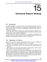
oil filters, auxiliary atomizing equipment, if used, and pumps (see Fig.
10.4).
Coal handling has not changed basically in 100 years, except that
it has become somewhat more mechanized. Coal is delivered from the
mine to the silo or coal pile, from which it is moved to a day hopper
Equipment: Part 2
Downloaded from Digital Engineering Library @ McGraw-Hill (www.digitalengineeringlibrary.com)
Copyright © 2004 The McGraw-Hill Companies. All rights reserved.
Any use is subject to the Terms of Use as given at the website.
Equipment: Part 2 331
Figure 10.4
Elementary oil fuel-handling system.
by elevators or conveyors and is fed into the boilers. Ash is disposed
of either mechanically or manually. In some large boilers, the fly ash
is reinjected to use as much of the free carbon as possible. Entraining
fly ash into overfire air also assists in developing turbulent conditions
in the combustion chamber.
10.6.6 Controls
Controls for automatic fuel-burning equipment range from simple two-
position on/ off controls to full modulating systems which measure flue
gas temperatures and constituents (O
2
,CO,CO
2
) and automatically
adjust fuel-airflow ratios for maximum combustion efficiency (Figs.
10.5 and 10.6). There is sometimes a tendency to ‘‘oversophisticate’’
the control system. The controls should be as simple as possible, com-
mensurate with the size and sophistication of the system and its op-
erators. In all cases, control systems must include safety devices and
procedures to prevent the development of hazardous conditions, in-
cluding high pressure, high temperature, low water level, flame fail-
ure, and the like.
10.6.7 Environmental considerations
Natural and LP gas fuels require no pollution controls except for ox-
ides of nitrogen in large boilers. Residual oils and solid fuels require
tail-end control equipment to remove particulate matter and sulfur
compounds. These are regulated by local, state, and federal codes.
Such equipment includes fabric filters (baghouses), electrostatic pre-
cipitators, dry and wet scrubbers, and controls to maximize combus-
Equipment: Part 2
Downloaded from Digital Engineering Library @ McGraw-Hill (www.digitalengineeringlibrary.com)
Copyright © 2004 The McGraw-Hill Companies. All rights reserved.
Any use is subject to the Terms of Use as given at the website.
332 Chapter Ten
Figure 10.5
On / off burner con-
trol system. (Courtesy of F.
Govan.)
tion efficiency. Some very exotic nitrogen and oxide control systems
are being marketed, but their value is limited and costs are high. They
should be evaluated as a developing technology.
10.7 Boiler Feedwater and Water
Treatment Systems
Hot water boilers require very simple makeup systems. The hot water
is used in a closed circuit, so water losses are minimal. Water softeners
and small amounts of chemical treatment may be employed for oxygen
scavenging and corrosion control. A simple shot feeder for adding
chemicals is shown in Fig. 10.7.
Steam boilers may require elaborate makeup and feedwater sys-
tems. Condensate, steam trap, fitting, and blowdown losses may be as
much as 15 to 20 percent of steam capacity. Some industrial plant
systems are designed for 100 percent makeup.
In small boiler systems, condensate is returned by gravity to a re-
ceiver and then is pumped into the boiler as required. Makeup water
is supplied to the condensate receiver along with water treatment
chemicals. Periodic or continuous blowdown is required to remove the
buildup of sediment and evaporated solids in the waterside of the
boiler. Figure 10.8 shows a typical boiler feed system with a Hartford
loop.
Equipment: Part 2
Downloaded from Digital Engineering Library @ McGraw-Hill (www.digitalengineeringlibrary.com)
Copyright © 2004 The McGraw-Hill Companies. All rights reserved.
Any use is subject to the Terms of Use as given at the website.
Equipment: Part 2 333
Figure 10.6
Full modulating burner control system. (Courtesy of F. Govan.)
In larger steam boilers and all high-pressure boilers, the feedwater
and treatment system can become complex (Fig. 10.9). Condensate is
returned to a receiver from which it is pumped to a deaerating feed-
water heater, which preheats the water and removes most of the dis-
solved oxygen; oxygen is very corrosive to the high-temperature wa-
terside surfaces. Zeolite softening or charcoal filtering is frequently
used for pretreatment of raw makeup water. Chemicals may be added.
All this treatment must be automatically controlled, but as simply as
possible. The water treatment program should be tailored to the spe-
cific conditions because all raw waters differ from each other. A water
treatment consultant should be used. Most treatments include blow-
down, pH control, and addition of chemicals to neutralize other con-
taminants. Great care must be taken when a new program is begun
for an existing boiler system. A new program may loosen accumulated
Equipment: Part 2
Downloaded from Digital Engineering Library @ McGraw-Hill (www.digitalengineeringlibrary.com)
Copyright © 2004 The McGraw-Hill Companies. All rights reserved.
Any use is subject to the Terms of Use as given at the website.
334 Chapter Ten
Figure 10.7
Shot feeder.
sludge and scale deposits, causing massive failures. Many boiler fail-
ures can be attributed to improper water treatment or overtreatment.
10.8 Boiler Codes and Standards
Boilers must be installed and operated in accordance with applicable
codes and standards. The local code authorities will refer to one or
more of the industry codes, especially the American Society of Me-
chanical Engineers (ASME) boiler code.
1
Other references will meet
the standards of the American Gas Association (AGA), the Hydronics
Institute (HYDI), the American Boiler Manufacturers’ Association
(ABMA), and insurance companies, such as Factory Mutual (FM) (par-
ticularly with respect to burner systems). Underwriters’ Laboratories
(UL) provides certification for some of the control and safety devices,
such as relief valves. The proposed design of the boiler system should
be submitted to the owner’s insurance company to ensure compliance
with requirements.
Equipment: Part 2
Downloaded from Digital Engineering Library @ McGraw-Hill (www.digitalengineeringlibrary.com)
Copyright © 2004 The McGraw-Hill Companies. All rights reserved.
Any use is subject to the Terms of Use as given at the website.
Equipment: Part 2 335
Figure 10.8
Boiler feed piping with Hartford loop.
Figure 10.9
Condensate return and boiler feedwater system.
Equipment: Part 2
Downloaded from Digital Engineering Library @ McGraw-Hill (www.digitalengineeringlibrary.com)
Copyright © 2004 The McGraw-Hill Companies. All rights reserved.
Any use is subject to the Terms of Use as given at the website.
336 Chapter Ten
10.9 Boiler Design
There is little that a client or consulting engineer can do to influence
the basic design of a boiler. However, clearly established performance
criteria can be used to ensure a long-lived, efficient system. Some of
these factors include:
1. Heat release per square foot of flat projected radiant surface, a
measure of the intensity of radiant heat transfer. A high value may
contribute to a short boiler life.
2. Combustion volume—the physical volume in the furnace necessary
for complete combustion. Too large or too small a volume may re-
duce efficiency.
3. Convection air unit tube spacing—critical when solid fuels are
used. Small spaces can easily be blocked by scale or ash.
4. Combustion efficiency based on accepted test procedures.
5. Flue gas temperature—critical in the prevention of condensation
and corrosion in the final sections of the boiler.
6. Physical size—especially important in existing structures where
installation access is limited.
In the design and installation of larger boilers and high-pressure
boilers, it is especially important that the design engineer have ex-
perience in the field, in order to properly evaluate the claims of com-
peting suppliers.
10.10 Acceptance and Operational Testing
Residential and small commercial boilers are seldom tested individu-
ally for combustion efficiency. For larger boilers and high-pressure
boilers, thermal testing in the field is usually required. The standard
test is the ASME power test code, short form, input/output test
method. It is expensive and time-consuming but provides accurate
measurement of actual performance. There are other tests, but any
simpler test is of questionable accuracy and will seldom yield consis-
tent results when it is repeated.
For operational testing, the operator should have, at the least, a
simple efficiency test kit, such as an ‘‘Orsat,’’ a ‘‘Baccharach,’’ or ‘‘Fy-
rite’’ gas absorption device. These devices or one of the newer auto-
matic gas sampling devices can be used on a regular basis to measure
efficiency and to indicate changes in performance. The instruments
measure flue gas temperature as well as the percentage of oxygen,
carbon monoxide, and carbon dioxide. By using a nomograph, the com-
Equipment: Part 2
Downloaded from Digital Engineering Library @ McGraw-Hill (www.digitalengineeringlibrary.com)
Copyright © 2004 The McGraw-Hill Companies. All rights reserved.
Any use is subject to the Terms of Use as given at the website.
Equipment: Part 2 337
Figure 10.10
Steam-to-water heat exchange.
bustion efficiency can be calculated from these data. Significant
changes—ע10 percent—must be investigated. Newer automatic gas
sampling equipment which simultaneously reads flue gas, oxygen, and
carbon monoxide is wonderful for regular testing of boiler perform-
ance.
10.11 Direct- and Indirect-Fired
Heating Equipment
A direct-fired heater is one in which the fuel is converted to heat en-
ergy at the point of use. The usual fuel is either electricity or a fuel
gas, either natural gas or liquefied petroleum gas (LP). Fuel oil is
seldom used. Direct fuel firing in an occupied space requires back-
ground ventilation, enough to dilute the products of combustion.
Indirect-fired heaters utilize a heated fluid, e.g., steam or hot water,
which is heated elsewhere and transported through a piping system
to the point of use.
10.12 Heat Exchangers—Water Heating
Heat exchangers for steam to water or water to water are commonly
of the shell-and-tube type similar to those described in Chap. 9. A
steam-to-water exchanger (Fig. 10.10) could also be called a steam con-
denser, because it is the latent heat of condensation which is being
used to heat the water. The steam is in the shell, the water in the
tubes. The system is controlled as shown in Fig. 10.11. For more ac-
curate control at light loads, it is common practice to use two control
valves in parallel, sequenced, with the smaller valve sized to handle
one-third of the load. It is more difficult to control with higher steam
Equipment: Part 2
Downloaded from Digital Engineering Library @ McGraw-Hill (www.digitalengineeringlibrary.com)
Copyright © 2004 The McGraw-Hill Companies. All rights reserved.
Any use is subject to the Terms of Use as given at the website.
338 Chapter Ten
Figure 10.11
Control for steam-to-hot water heat exchanger.
pressures; for small heat exchangers it may be desirable to provide a
steam-pressure-reducing station (see Fig. 6.1).
A water-to-water heat exchanger (Fig. 10.12) may be used in many
ways. When it is used with high-temperature water (HTW), the HTW
is always in the tubes. This provides an extra measure of safety since
the tubes are more easily rated for higher pressures than is the shell.
The control valve may be a two-way or a three-way type, as shown in
Fig. 10.13. This may be part of a cascade arrangement, shown in Fig.
6.3. Two-way valves are used in variable-flow systems.
10.13 Heat Exchangers—Air Heating
A heat exchanger coil for air heating is of the finned-tube type, as
described in Sec. 9.7. Steam-to-air coils are frequently made in a dou-
ble-tube configuration (Fig. 10.14). The steam is supplied to the inner
tube, which has a number of small metering orifices through which
the steam passes to the outer tube. The result is a more or less uni-
Equipment: Part 2
Downloaded from Digital Engineering Library @ McGraw-Hill (www.digitalengineeringlibrary.com)
Copyright © 2004 The McGraw-Hill Companies. All rights reserved.
Any use is subject to the Terms of Use as given at the website.